7
Programming
2.3.1
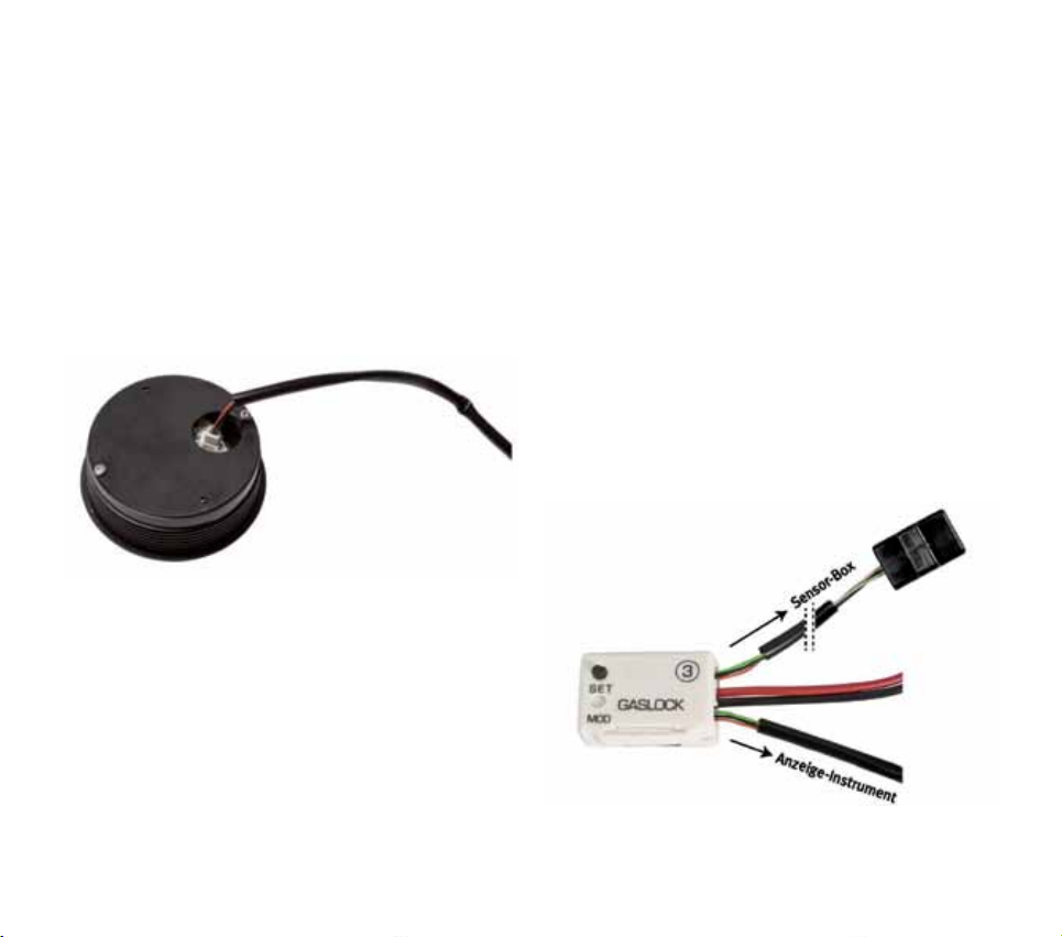
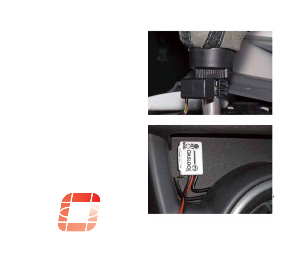
Fastening the reference box:
The box should be placed as horizontally as pos-
sible in the area of the switching lever. Labelling
points up. (Fig. 5)
2.3.2
Remove protective foil from the adhesive strips,
position reference box and press on firmly.
Verify that the gear lever is still set to idle. Now
acknowledge the box position by briefly pressing
the push-button.
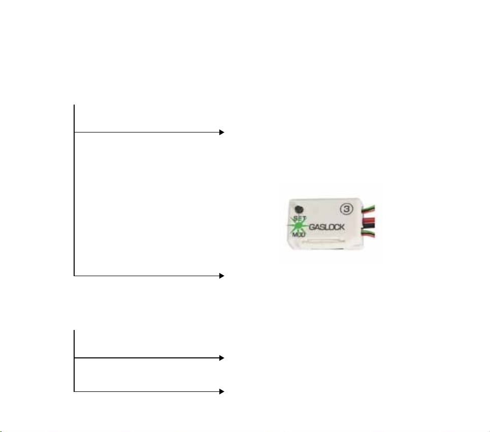
2.3.3
Gear programming now starts. Starting in first
gear, the display now shows all gears in sequen-
ce as flashing figures.
2.1.1
The vehicle should be placed on a surface that
is as level as possible before programming.
Since the vehicle has to start in first gear after
programming (light acceleration), please ensure
now that there are no obstacles (20 metres
straight on are sufficient) and that traffic is not
impaired.
2.1.2
Start the engine – gear lever set to idle!
2.2.1
LCD Colour selection:
(Colour change by position change of the refe-
rence box). Keep the reference box button (3)
pressed for approx. 5 s until „C“ is displayed,
then let go of the button.
Tilt the reference box forwards and backwards
in your hand to start colour selection. The colour
changes in small nuances when the reference
box position is adjusted slightly. Briefly confirm
desired colour by pressing the push-button on
the reference box once. Display now indicates a
transverse bar: