Gasmet DX4040 Parts list manual

DX4040 FTIR Gas Analyzer
On-site Series
Instruction and Operating Manual
Version E2.04 (July 23, 2013)

DX4040 INSTRUCTION AND OPERATING MANUAL (E2.04)
WARRANTY STATEMENT
This warranty applies to the Gasmet brand name products sold with this warranty
statement. This warranty is applicable in all countries and may be enforced in any
country where Gasmet Technologies Oy or its subsidiaries or its authorised service
providers offer warranty service subject to the terms and conditions set forth in this
warranty statement.
Gasmet Technologies Oy and its subsidiaries guarantee that all products manufactured
and sold by it are free of defects in materials and workmanship under normal use
during the warranty period.
The products of Gasmet Technologies Oy and its subsidiaries are manufactured using
new materials or new and used materials equivalent to new in performance and
reliability. Spare parts may be new or equivalent to new.
Gasmet Technologies Oy and its subsidiaries agree to either replace or repair free of
charge (Ex Works Helsinki, Incoterms 2000) any such defective product or part that is
returned to its repair facility within one (1) year of the delivery date. All parts or products
removed under this warranty become the property of Gasmet Technologies Oy or its
subsidiaries. The replacement product or part takes on the warranty status of the
removed product or part.
The warranty does not extend to any product from which the serial number has been
removed or that has been damaged or rendered defective (a) as a result of accident,
misuse, abuse, normal wear of components or other external causes; (b) by operation
outside the usage parameters stated in the user documentation that is provided with the
product; (c) by the use of parts not manufactured by Gasmet Technologies Oy and its
subsidiaries; or (d) by modification or service by anyone other than Gasmet
Technologies Oy and its subsidiaries.
Gasmet Technologies Oy and its subsidiaries are not liable for any damages caused by
the product or the failure of the product to perform, including any loss of profits or
savings, incidental damages, or consequential damages.
Gasmet Technologies Oy shall not be liable for technical or editorial errors or omissions
contained herein. The information in this document is provided “as is” without guarantee
of any kind and is subject to change without notice. Should you find any errors, we
would appreciate if you notified us.
Gasmet™, Calcmet™, Calcmet Lite™, and GICCOR™ are trademarks of Gasmet
Technologies Oy. Windows® is a registered trademark of Microsoft Corporation. Teflon®
is a registered trademark of E.I. du Pont de Nemours & Co., Inc. Viton® and Kalrez® are
registered trademarks of DuPont Dow Elastomers. Bluetooth® is a registered trademark
of Bluetooth SIG, Inc.
2
DX4040 INSTRUCTION AND OPERATING MANUAL (E2.04)
WARNING. READ BEFORE USING ANALYSER
To avoid possible electrical shock or personal injury, follow these guidelines:
- Use the analyser only as specified in this manual or the analyser could be irreversibly
damaged.
- Do not use the analyser or probe or external AC/DC power supply unit1 or battery if
they appear damaged, or if they operate incorrectly. If in doubt, have the analyser
serviced by trained service personnel.
- Always use the proper original Gasmet parts, and respect Gasmet suggested
measurement conditions.
- Do not apply an input AC voltage to the external AC/DC power supply unit different
than what indicated on the external AC/DC power supply unit name plate.
- Always use a proper earth ground under external AC/DC power supply unit use.
- Do not use the analyser in EX rated areas.
- The equipment2 must not be operated in wet conditions.
- Do not drop the analyser.
- The DX4040 Instruction and Operating Manual should be read and understood before
operating your unit.
Symbols
AC (Alternating Current)
DC (Direct Current)
Important Information; refer to manual
WEEE symbol (Waste Electrical and
Electronic Equipment Directive)
Conforms to European Union directives Canadian Standards Association
1: AC/DC PSU will later refer to external AC/DC power supply unit.
2: Equipment refer to the external AC/DC power supply unit, the battery and the
analyser.
3

DX4040 INSTRUCTION AND OPERATING MANUAL (E2.04)
CONTENTS
WARRANTY STATEMENT ........................................................................................................2
WARNING. READ BEFORE USING ANALYSER ................................................................3
CONTENTS...................................................................................................................................4
FIGURES.......................................................................................................................................7
TABLES.........................................................................................................................................8
PREFACE......................................................................................................................................9
1INTRODUCTION..................................................................................................................10
2SUPPLIED GOODS...............................................................................................................11
2.1 PACKAGE...........................................................................................................................11
2.2 LIST OF ITEMS DELIVERED FOR DX4040.........................................................................11
2.3 GASMET CONFIGURATION.................................................................................................12
3PRINCIPLE OF MEASUREMENT.....................................................................................13
3.1 PRINCIPLES OF INFRARED SPECTROSCOPY .....................................................................13
3.2 COMPONENTS OF A FOURIER TRANSFORM INFRARED SPECTROMETER.........................15
3.3 QUANTITATIVE ANALYSIS OF FTIR SPECTRA ..................................................................17
3.4 MULTI-COMPONENT ANALYSIS..........................................................................................18
3.5 THE SPECTRAL RESOLUTION OF FTIR ANALYSIS ...........................................................19
4GASMET DX4040 FTIR GAS ANALYSER .......................................................................21
4.1 INTRODUCTION...................................................................................................................21
4.1.1 Applications of the Gasmet DX4040 Analyser .................................................21
4.1.2 Structure of the Gasmet DX4040 Analyser.......................................................21
4.2 GASMET DX4040 TECHNICAL SPECIFICATIONS..............................................................22
4.2.1 General Parameters .............................................................................................22
4.2.2 Spectrometer .........................................................................................................23
4.2.3 Sample Cell............................................................................................................23
4.2.4 Measuring Parameters .........................................................................................24
4.2.5 Electrical Connectors............................................................................................24
4.2.6 Gas Inlet and Outlet Conditions..........................................................................24
4.2.7 Electronics..............................................................................................................25
4.2.8 Analysis Software..................................................................................................25
4.2.9 Additional Information...........................................................................................25
4.3 GASMET DX4040 TECHNICAL DESCRIPTION...................................................................26
4.3.1 Analyser Enclosure ...............................................................................................26
4.3.2 Power Supply.........................................................................................................27
4.3.3 Front Panel.............................................................................................................29
4.3.4 On-board Sample Pump ......................................................................................35
4.3.5 On-board Fans.......................................................................................................35
4.3.6 Probe.......................................................................................................................36
4.3.7 Carrying Handle, Shoulder strap and Carrying Harness ................................36
4

DX4040 INSTRUCTION AND OPERATING MANUAL (E2.04)
4.3.8 Personal Digital Assistant (PDA) ........................................................................36
4.3.9 Optional Computer................................................................................................36
5EQUIPMENT INSTALLATION..........................................................................................38
5.1 STORAGE AND PACKAGING CONDITIONS .........................................................................38
5.2 OPERATING CONDITIONS ..................................................................................................38
5.2.1 Lifting and Carrying Instructions .........................................................................38
5.2.2 Installation Location ..............................................................................................39
5.2.3 Ventilation Requirements.....................................................................................39
5.2.4 Operating Requirements......................................................................................39
5.2.5 Protective Earthing Instructions ..........................................................................40
5.2.6 Supply Connection................................................................................................40
5.2.7 Sound Level ...........................................................................................................41
5.2.8 Explosion Protection .............................................................................................41
6EQUIPMENT OPERATION ................................................................................................42
6.1 QUICK PDAGUIDE ...........................................................................................................42
6.2 SOFTWARE SETUP ............................................................................................................42
6.2.1 Software Pre-requirements..................................................................................43
6.2.2 Synchronization PDA/Computer.........................................................................43
6.2.3 HASP Key Driver Installation...............................................................................44
6.2.4 USB to Serial Converter Installation...................................................................44
6.2.5 Calcmet Software Installation..............................................................................46
6.2.6 Calcmet Library Installation .................................................................................47
6.2.7 Calcmet Software Configuration.........................................................................47
6.2 ZERO CALIBRATION AND HARDWARE STATUS CHECK ....................................................47
6.3 CALCMET APPLICATION CREATION ..................................................................................48
6.4 CALCMET LITE USER’S GUIDE AND REFERENCE MANUAL..............................................49
6.4.1 Calcmet Lite Application Installation ..................................................................49
6.4.2 PDA Configuration ................................................................................................49
6.4.3 CALCMETLITE.INI File ........................................................................................49
6.4.4 Calcmet Lite Install/Uninstall ...............................................................................51
6.4.5 Operating DX4040 via Bluetooth ........................................................................51
6.4.6 Hardware Status....................................................................................................52
6.4.7 Zero Calibration .....................................................................................................53
6.4.8 Measurements .......................................................................................................55
6.4.9 Emailing Results and Spectra.............................................................................58
6.4.10 Checking Storage Space .....................................................................................59
6.4.11 Flushing and Switching Off DX4040 via Bluetooth..........................................59
6.4.12 Transferring of Spectrum/Results Files .............................................................60
6.4.13 Application Selection ............................................................................................60
6.4.14 Update Calcmet Lite Settings..............................................................................61
6.5 MEASUREMENTS SUMMARY..............................................................................................62
7EQUIPMENT MAINTENANCE AND SERVICE .............................................................63
7.1 SAFETY PRECAUTIONS......................................................................................................63
7.2 PARTS INFORMATION ........................................................................................................63
7.3 MAINTENANCE PLAN .........................................................................................................64
7.4 ENCLOSURE CLEANING.....................................................................................................64
7.5 REPLACING/CLEANING DUST FILTERS.............................................................................65
7.6 REPLACING PROBE FILTER...............................................................................................65
5

DX4040 INSTRUCTION AND OPERATING MANUAL (E2.04)
7.7 VISUAL INSPECTION...........................................................................................................66
7.8 SAMPLE CELL INSPECTION ...............................................................................................66
7.9 REPLACEMENT OF OPTOELECTRONIC COMPONENTS......................................................66
8ANALYSER INSPECTION ..................................................................................................67
APPENDIX A: BLUETOOTH SETUP..........................................................................................68
APPENDIX B: INSTALL/UNINSTALL CALCMET LITE .....................................................69
APPENDIX C: LI-ION BATTERIES GENERAL USAGE INSTRUCTIONS .....................70
APPENDIX D: RECOMMENDATIONS TO THE END-USERS OF BATTERIES............71
APPENDIX E: LASER SAFETY INFORMATION.................................................................72
APPENDIX F: CERTIFICATION..............................................................................................73
APPENDIX G: VOCABULARY................................................................................................74
APPENDIX H: GASMET SALES AND SUPPORT OFFICES............................................75
6

DX4040 INSTRUCTION AND OPERATING MANUAL (E2.04)
FIGURES
Figure 1. The four normal modes of vibration of carbon dioxide CO2 molecule. ............14
Figure 2. An absorbance spectrum of carbon dioxide CO2 measured with a DX-4015
model. c(CO2) = 50 ppm, T = 50 oC, absorption path length = 9.8 m.........................15
Figure 3. The basic components of an FTIR spectrometer are infrared source,
interferometer, sample cell, detector, and signal and data processing unit...............15
Figure 4. A Michelson interferometer is a unique part of an FTIR spectrometer............16
Figure 5. A typical interferogram.............................................................................................17
Figure 6. An example of spectra for multi-component analysis. The spectral analysis
routine in Calcmet Lite software performs all calculations automatically. ..................19
Figure 7. Basic structure of the Gasmet DX4040 analyser. ...............................................22
Figure 8. Dimensional drawing of the DX4040 analyser enclosure. .................................26
Figure 9. Battery LED indicator. ..............................................................................................28
Figure 10. Front panel: sample gas fittings and connectors of the DX4040 model. ......29
Figure 11. Gas fittings...............................................................................................................30
Figure 12. User Account Control settings..............................................................................43
Figure 13. Calcmet Welcome window....................................................................................47
Figure 14. Calcmet calibration information............................................................................48
Figure 15. Correct Calcmet Lite start-up sequence.............................................................52
Figure 16. Calcmet Lite Hardware Status. ............................................................................52
Figure 17. Calcmet Lite zero calibration. ...............................................................................54
Figure 18. Activate pump during continuous measurement...............................................54
Figure 19. Save spectrum files................................................................................................55
Figure 20. START - STOP measurement. ............................................................................56
Figure 21. Measurement results (spectrum or analysis).....................................................57
Figure 22. Scrolling the results................................................................................................57
Figure 23. E-mailing options....................................................................................................59
Figure 24. Storage information................................................................................................59
Figure 25. Switch off the analyser. .........................................................................................60
Figure 26. Application selection. .............................................................................................60
Figure 27. Calcmet Lite settings. ............................................................................................61
Figure 28. Dust filters cleaning................................................................................................65
Figure 29. Probe filter cleaning. ..............................................................................................66
7

DX4040 INSTRUCTION AND OPERATING MANUAL (E2.04)
TABLES
Table 1. Power switch in Off mode. ........................................................................................32
Table 2. Power switch in Cable mode. ...................................................................................32
Table 3. Power switch in Bluetooth mode..............................................................................33
Table 4. Battery relative state of charge status. ...................................................................34
Table 5. Battery charging – LED status. ................................................................................34
Table 6. Battery relative state of charge status (0 % to 10 %)...........................................34
Table 7. Battery disconnected. ................................................................................................34
Table 8. Battery temperature or charger temperature not correct.....................................34
Table 9. AC/DC PSU error. ......................................................................................................35
Table 10. SMBus error..............................................................................................................35
Table 11. Charger communication error................................................................................35
Table 12. Hardware status results. .........................................................................................48
Table 13. Maintenance plan.....................................................................................................64
8

DX4040 INSTRUCTION AND OPERATING MANUAL (E2.04)
PREFACE
Thank you for choosing Gasmet, the state-of-the-art FTIR gas analyser manufactured
by Gasmet Technologies Oy. Gasmet is a high-technology product made of high quality
components.
The substantial investment of Gasmet Technologies Oy in R & D is targeted at
innovative, customer-driven solutions. Working closely with customers and global
distribution network, the company offers extensive technical applications support
services. Along with high reliability, the products of Gasmet Technologies Oy offer easy
operation and consistent and accurate results, together with competitive pricing.
The development of the powerful technology of FTIR has required uncompromising
commitment and expertise in several fields of high technology. As a result, the products
of Gasmet Technologies Oy are not only superior in performance, but also simple to
operate and maintain. The continuing philosophy of Gasmet Technologies Oy is to
provide reliable measurements in a variety of industrial applications now and in the
future.
Wherever you are and whatever your applications are, we hope you will find the
Gasmet gas analyser and its accessories fast, accurate, reliable, and easy to use.
9

DX4040 INSTRUCTION AND OPERATING MANUAL (E2.04)
1 INTRODUCTION
This instruction and operating manual provides information of the Gasmet DX4040
Fourier transform infrared (FTIR) gas analyser. Please read this manual carefully and
thoroughly prior to using the analyser. Improper use of the analyser may damage the
equipment.
Chapter 2 Supplied Goods provides general information regarding the content of the
Gasmet DX4040 package.
Chapter 3 Principle of Measurement discusses theoretical aspects of infrared
spectroscopy. These fundamentals help understanding the physical principles the
Gasmet FTIR system is based on.
Chapter 4 Gasmet DX4040 FTIR Gas Analyser provides information about the
Gasmet DX4040 hardware, the intended use of the equipment, technical specifications
and equipment ratings.
Chapter 5 Equipment Installation provides information of installing the Gasmet
DX4040 gas analyser and specific commissioning instructions. Additionally, warnings
against hazards, which could arise during installation or commissioning of the
equipment, are given. Use this chapter to get the equipment from storage into
operational condition.
Chapter 6 Equipment Operation provides instructions on how to use the Gasmet
DX4040. This chapter is recommended to read before any operation.
Chapter 7 Equipment Maintenance and Service describes the maintenance and
inspection of the equipment that are necessary periodically.
Chapter 8 Analyser Inspection describes what should be done when the analyser is
used the first time. This chapter includes an inspection sheet, which should be filled in
within 30 days from the date of delivery to ensure that the warranty is valid in full.
This instructions manual is copyrighted 2005 - 2013 by Gasmet Technologies Oy.
All rights reserved. No part of this manual may be reproduced in whole or in part
in any form without a prior written permission by Gasmet Technologies Oy.
10

DX4040 INSTRUCTION AND OPERATING MANUAL (E2.04)
2 SUPPLIED GOODS
2.1 Package
Gasmet DX4040 is shipped in a wooden box or in a dedicated transport case (optional).
To open the box, first open the lid of the box. Remove any additional smaller items on
the top of the analyser. Finally lift the analyser out of the box. A laminated paper
describing the list of items delivered with Gasmet DX4040 is included in the shipment.
Please, check that all the items ordered are included in the package and report to
Gasmet Technologies Oy if some parts are missing.
2.2 List of Items Delivered for DX4040
The standard package contains:
• Gasmet DX4040 FTIR gas analyser.
• One DX4040 carrying kit (including carrying harness, adjustable shoulder strap,
PDA carrying case, battery carrying case and four rubber straps).
• One Gasmet battery for DX4040.
• One serial to USB converter.
• One AC/DC PSU for DX4040.
• One serial cable for DX4040.
• One power supply cord.
• One PDA + Charger running Windows Mobile 6.1.
• One sample probe with one 1.5 m Tygon® tube including two inserts, one 5 m
Tygon® tube, three coupling inserts and one set of probe filters (five pieces).
• One Gasmet DVD-ROM including:
1. Application Tools folder (ADS application tools and Gasmet Tools application
tools)
2. Gasmet Software folder
a) Calcmet Lite setup
b) Calcmet v12.xx setup
3. Quality Documents folder (ISO 9001 Certificate)
4. User Manuals folder
a) Gasmet DX4040 FTIR Gas Analyser Instruction and Operating Manual
b) Calcmet User Manual
5. Calcmet LiteLibrary folder, which includes
a) instrument-specific reference files
b) reference spectra Excel sheet (description of the reference spectra)
c) library and configuration files for analyser, components file for Calcmet Lite
6. Test folder (factory-measured SNR spectra, background spectra, and .ini file).
11

DX4040 INSTRUCTION AND OPERATING MANUAL (E2.04)
The options available are:
• Coupling insert for DX4040 in the analyser end.
• Transport case designed for DX4040.
• External battery charger for DX4040 including external charger, USB cable and
AC/DC PSU.
• Additional AC/DC PSU.
• Additional Gasmet batteries.
• Additional set of filters.
• Additional serial cable.
• DX40XX PRO key for Calcmet software.
• Additional serial to USB converter.
• PTFE probe filter for DX4040.
2.3 Gasmet Configuration
The following functions have been factory set up in accordance with customer order
specification:
• Installation of software and analysis options in Calcmet Lite software.
• Library and analysis options in Calcmet library if the PRO Key option ordered.
12

DX4040 INSTRUCTION AND OPERATING MANUAL (E2.04)
3 PRINCIPLE OF MEASUREMENT
3.1 Principles of Infrared Spectroscopy
Infrared (IR) spectroscopy is a technique for chemical analysis and determination of
molecular structure in solid, liquid, and gas state. The principles that molecular
vibrations occur in the infrared region of the electromagnetic spectrum and functional
groups in chemical compounds have characteristic absorption frequencies are the basis
of this technique. The frequencies of the most interest range from 2.5 to 16 µm.
However, in IR spectroscopy it is common to use the reciprocal of the wavelength,
called 'wave number', and thus this range becomes 4000 - 625 cm-1.
An absorption spectrum demonstrates graphically to what extent the sample gas
absorbs the different wavelengths of the infrared radiation. The spectrum shows the
transmission of the infrared radiation through the gas as a function of wavelength. For
each wavelength, the transmittance T is the intensity of the infrared radiation that has
passed through the sample gas divided by the intensity of the infrared radiation that has
entered the sample gas. When there is no absorption, the value of transmittance T is 1
(or 100 %), which indicates that 100 % of the infrared radiation at that wavelength goes
through the sample gas. If the intensity of the radiation entering the sample is I0 and the
intensity of the radiation that has passed through the sample is I, the transmittance T is:
Besides using transmittance T, the absorbance scale presents the absorption of the
infrared radiation. Absorbance A is equal to the logarithm of the transmittance
reciprocal:
The advantage of using the absorbance scale is that the value of absorbance is directly
proportional to the thickness of the sample gas (absorption path length), and the
concentration of the sample gas.
T = I / I
o
,
T = transmittance
I = passed intensity
I = incident intensity
A = log
10
(I / T),
A = absorbance
T = transmittance
13

DX4040 INSTRUCTION AND OPERATING MANUAL (E2.04)
Figure 1 shows how a carbon dioxide CO2 molecule behaves when it interacts with
infrared radiation. All different vibrations, rotations, and their combinations result in
absorption bands of specific wavelengths of the infrared radiation.
Figure 1. The four normal modes of vibration of carbon dioxide CO2 molecule.
The infrared absorption spectrum is unique to all different gas molecules. It is possible
to identify any gas component from its IR spectrum. Figure 2 shows a carbon dioxide
CO2 infrared absorbance spectrum. It can be seen that the anti-symmetric vibration
band at 2349 cm-1 is the most intensive band while others are either outside of the
range (900 - 4220 cm-1) or too weak in intensity. The band at ~3660 cm-1 is the
combination band (i.e. sum) of υ1 and υ2.
Symmetric stretch υ
1
at 1388 cm-1
(This mode is not infrared active)
Anti-symmetric stretch υ
3
at 2349 cm-1
In-plane bend υ
2
at 667 cm-1
Out-of-plane bend υ
2
at 667 cm-1
OCO
14
DX4040 INSTRUCTION AND OPERATING MANUAL (E2.04)
Figure 2. An absorbance spectrum of carbon dioxide CO2 measured with a DX-4015
model. c(CO2) = 50 ppm, T = 50 oC, absorption path length = 9.8 m.
3.2 Components of a Fourier Transform Infrared Spectrometer
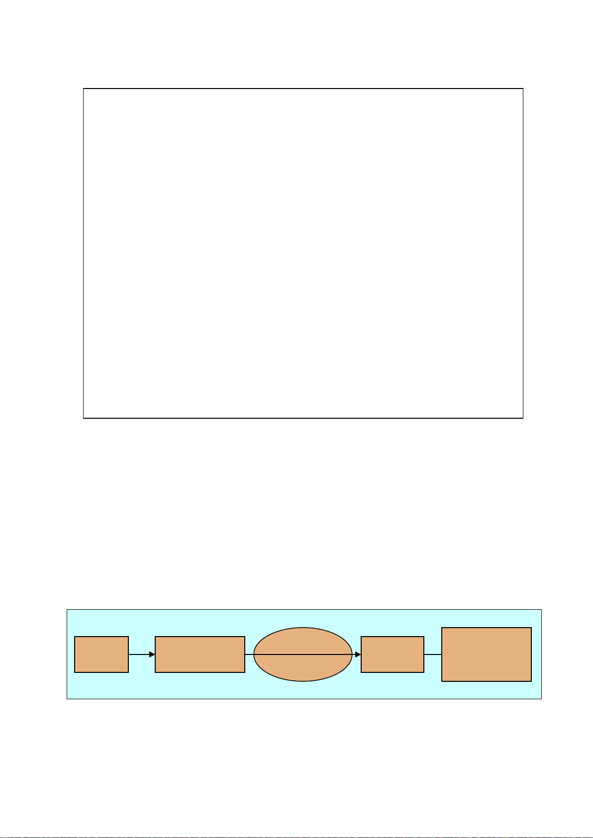
Figure 3 shows the basic parts that are typical for all non-dispersive FTIR
spectrometers. A parallel, polychromatic radiation from an IR source is directed to an
interferometer. The modulated beam is reflected through the gas sample cell. Finally,
the detector detects the intensity of the infrared beam. The detected signal is digitized
and Fourier transformed by the computer resulting in an IR spectrum of the sample gas.
Figure 3. The basic components of an FTIR spectrometer are infrared source,
interferometer, sample cell, detector, and signal and data processing unit.
Infrared
source
Interferometer
Detector
Signal and
data processing
unit
Sample
cell
15
DX4040 INSTRUCTION AND OPERATING MANUAL (E2.04)
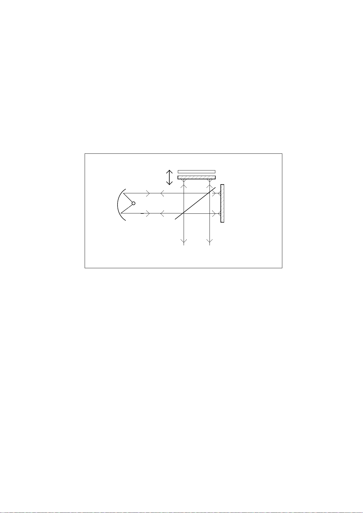
The unique part of an FTIR spectrometer is the interferometer. Figure 4 shows a
Michelson type interferometer. A mirror collects and collimates the infrared radiation
from the source before it strikes the beam splitter. The beam splitter ideally transmits
one-half of the radiation, and reflects the other half. Both transmitted and reflected
beams strike plane mirrors, which reflect the two beams back to the beam splitter.
Thus, one-half of the infrared radiation that finally goes to the sample gas has first been
reflected from the beam splitter onto the moving mirror, and then back to the beam
splitter. The other half of the infrared radiation going to the sample gas has first gone
through the beam splitter and then reflected from the fixed mirror back onto the beam
splitter. When these two beams from two optical paths are reunited, interference occurs
at the beam splitter. The strength of the interference is depended on the optical path
difference between the beams caused by the position of the moving mirror.
Sour ce
Beamspl i t ter
Radi ati on t o the sampl e gas and detect or
M ovi ng mi rror
Fixed mirror
Figure 4. A Michelson interferometer is a unique part of an FTIR spectrometer.
The optical path length difference (OPD) between the two optical paths of a Michelson
interferometer is two times the physical displacement of the moving mirror. An
interferogram is the interference signal measured by the detector as a function of the
OPD. Figure 5 shows a typical interferogram produced by the interferometer. The graph
shows the intensity of the infrared radiation as a function of the displacement of the
moving mirror. At the peak position, the optical path length is the same for the radiation
that comes from the moving mirror as it is for the radiation that comes from the fixed
mirror.
16

DX4040 INSTRUCTION AND OPERATING MANUAL (E2.04)
Figure 5. A typical interferogram.
The spectrum is computed from the digitized interferogram by performing a Fourier
transform by a computer utilizing a Fast Fourier Transform (FFT) algorithm.
3.3 Quantitative Analysis of FTIR Spectra
The basic law for spectroscopic quantitative analysis is Beer's law (also known as the
Beer-Lambert law). It shows how the concentration of the sample gas is related to the
measured absorbance of the sample spectrum:
log( / ) log( / )I I T A abc
01= = =
Io = intensity of infrared radiation entering the sample
I = intensity of the infrared radiation that has passed through the sample
A = absorbance
T = transmittance
a = a (υ) = absorptivity (depends on wavelength)
b = optical path length
c = sample concentration
The absorptivity a characterizes the capacity of the molecule to absorb infrared
radiation. The value of a varies from a molecule to another and as a function of
wavelength, but is constant for a given molecule at a given wavelength. The quantity b
is the optical path length, that is, the distance the infrared radiation beam traverses in
the gas sample. The quantity c indicates the concentration of the sample gas molecules
in the sample. If the optical path length is constant, Beer's law states that the
Voltage U (mv)
Optical path difference x/2 (cm-1)
- L 0+ L
17

DX4040 INSTRUCTION AND OPERATING MANUAL (E2.04)
pV = nRT,
p = pressure
V = volume
n = number of gas molecules
R = gas constant = 8.314 JK-1mol-1
T = temperature
absorbance is directly proportional to the concentration of the sample gas at a given
wavelength. Since Beer's law is additive, the total absorbance A is equal to the sum of
the values of A of each gas component.
Two conditions limit the use of the Beer's law in practice. The radiation is
monochromatic, and the sample absorptivity does not vary with concentration. If the
sample concentration range is wide, the change in the sample environment can cause
absorptivity changes and deviations from Beer's law. For narrow concentration ranges
and for low absorbance values a plot of concentration versus absorbance is nearly
linear.
The changes in the gas pressure caused by molecular collisions may bring about
broadening in the absorption line shape of the sample gas. This affects all infrared
bands. As the temperature increases, the population distribution of the molecules in
different energy levels changes. The changes in the temperature cause changes in the
absorption line shape of the sample gas. To measure the concentration of a gas
compound, it is necessary to calculate the number of gas molecules in the sample cell.
The number of the gas molecules in the sample cell depends linearly on both the gas
pressure and the volume of the sample cell, and reciprocally on the gas temperature
(ideal gas equation of state):
Any changes in sample gas temperature and/or pressure in the sample cell directly
affect the measured gas compound concentration. In addition, gas pressure or
temperature changes may affect the line shape of the measured absorbance spectrum,
and thus the accuracy of the analysis results.
3.4 Multi-component Analysis
The degree of absorption of infrared radiation at each wavelength relates quantitatively
to the number of absorbing molecules in the sample gas. Since there is a linear
relationship between the absorbance and the number of absorbing molecules,
quantitative multi-component analysis of gas mixtures is feasible.
To perform multi-component analysis we need a sample spectrum. In addition, we need
reference spectra of all the gas components that may exist in the sample. A reference
spectrum is a spectrum of one single gas component of specific concentration. In multi-
component analysis, we try to combine these reference spectra with appropriate
multipliers in order to get a spectrum that is as close as possible to the sample
spectrum. If we succeed in forming a spectrum similar to the sample spectrum, we get
the concentration of each gas component in the sample gas using the multipliers of the
individual reference spectra, if we know the concentrations of the reference gases.
18

DX4040 INSTRUCTION AND OPERATING MANUAL (E2.04)
For example, suppose we have a sample spectrum and reference spectra like those
shown in Figure 6. In this case, we know that the sample gas consists of gases
Reference 1 and Reference 2. We have the reference spectra available and we know
that these reference spectra represent concentrations of 10 ppm and 8 ppm,
respectively. To find out the concentration of each component in the sample gas, we try
to form the measured sample spectrum using a linear combination of the two reference
spectra. We find out that if we multiply the spectrum Reference 1 by 5 and the
spectrum Reference 2 by 2, and combine these two spectra we get a spectrum that is
similar to the sample spectrum. Accordingly, the sample gas contains reference gas 1
at five times the amount in the reference spectrum 1, and reference gas 2 at two times
the amount in the reference spectrum 2. The analysis indicates that the sample indeed
consists of these two reference gases. The concentration of the reference gas 1 in the
sample is found to be 50 ppm (= 5 x 10 ppm), and the concentration of the reference
gas 2 in the sample is 16 ppm (= 2 x 8 ppm).
0
0.05
0.1
0.15
0.2
0.25
0.3
Sample
Reference 1
Reference 2
Figure 6. An example of spectra for multi-component analysis. The spectral analysis
routine in Calcmet Lite software performs all calculations automatically.
3.5 The Spectral Resolution of FTIR Analysis
The spectral resolution of the measurement indicates how accurately it is possible to
separate different wavelengths of radiation in the absorption spectrum. High resolution
allows one to detect visually the exact location of narrow absorbance peaks and
reduces spectral overlap. If it were possible to achieve infinite resolution, no deviations
of Beer's law due to wide concentration range would occur. Thus, it would seem
beneficial to have high resolution in order to get good results for the analysis. However,
increasing the resolution causes other problems. For example, spectral noise increases
and makes the analysis less precise.
Furthermore, as high a resolution as possible does not maximize the information
content of the measurement. Jaakkola et al. have shown1 that low-resolution FTIR
spectroscopy offers some valuable advantages compared to the traditional high-
resolution FTIR gas phase spectroscopy, especially in non-laboratory environments.
1See, for example, P. Jaakkola, J. D. Tate, M. Paakkunainen, J. Kauppinen, and P. Saarinen, "Instrumental Resolution Considerations for
Fourier Transform Infrared Gas-Phase Spectroscopy," Applied Spectroscopy 51 (1997) 1159 - 1169.
Absorbance (in absorbance units)
Wave number (cm-1)
19

DX4040 INSTRUCTION AND OPERATING MANUAL (E2.04)
This makes the use of low resolution quite worthwhile. To achieve precise quantitative
analysis results, a low-resolution measurement should be used if the spectral analysis
program can mathematically solve the spectral overlap.
There are two reasons for the increase of the signal-to-noise ratio of an FTIR spectrum:
• In an FTIR spectrometer, the length of the measured interferogram determines the
resolution. The longer the interferogram, the more data points is required, and the
higher the resolution. In a high-resolution study, the time required by a single
measurement is also long, so that we are able to accumulate less data in a fixed
time, leading to higher noise level. Thus, the longer the measured interferogram is,
the lower the signal-to-noise ratio.
• High resolution requires a small aperture to prevent a phenomenon called aperture
broadening. Small aperture, in turn, reduces the signal and thus signal-to-noise
ratio.
20
Table of contents
Other Gasmet Measuring Instrument manuals


Popular Measuring Instrument manuals by other brands

Thyracont
Thyracont VD9CV operating instructions

Ambient Weather
Ambient Weather WS-YG901 manual

Lutron Electronics
Lutron Electronics CM-9942G Operation manual

PeakTech
PeakTech 3260 Operation manuals

TR-Electronic
TR-Electronic CEH-110 Assembly instruction

Bosch
Bosch Professional GSL 2 Original instructions


