Thyracont VD9CV User manual

Vakuum Mess- und Regelgerät VD9CV
Vacuum Measurement and Control Unit VD9CV
Appareil de mesure et de contrôle du vide VD9CV
Bedienungsanleitung
Operating Instructions
Mode d’emploi

2

3
1Allgemeine Hinweise ............................4
2Beschreibung ........................................5
3Installation .............................................6
3.1 Anschlüsse.........................................6
3.1.1 Signaleingänge 4 - 20 mA.......6
3.1.2 Signaleingang 0 - 10 V............6
3.1.3 Analogausgang 0 - 10 V..........7
3.1.4 Ventil-Anschlüsse....................8
3.1.5 RS232 Schnittstelle.................9
3.2 Inbetriebnahme..................................9
4Bedienung............................................10
4.1 Einschalten ......................................10
4.2 Konfiguration....................................11
4.2.1 Einheit....................................11
4.2.2 Nachjustierung.......................12
4.2.3 Messumformer-Typ ...............14
4.2.4 Ventiltyp Vakuum...................15
4.2.5 Ventiltyp Belüftung.................15
4.2.6 Stopfunktion...........................16
4.2.7 Skalierung Analogausgang ...17
4.3 Schaltpunkte ....................................18
4.4 Gasart ..............................................21
4.5 Serielle Schnittstelle.........................22
5Wartung und Pflege............................22
6Zubehör................................................22
7Technische Daten ...............................23
1General Information ............................. 4
2Description............................................ 5
3Installation............................................. 6
3.1 Connectors........................................ 6
3.1.1 Signal Inputs 4 - 20 mA .......... 6
3.1.2
Signal Input 0 - 10 V
.............
6
3.1.3 Analog Output 0 - 10 V........... 7
3.1.4 Valve Connectors.................... 8
3.1.5 RS232 Interface...................... 9
3.2 Initial Start-Up.................................... 9
4Operation............................................. 10
4.1 Power On......................................... 10
4.2 Configuration ................................... 11
4.2.1 Unit........................................ 11
4.2.2 Readjustment........................ 12
4.2.3 Transducer-Type................... 14
4.2.4 Type Vacuum Valve.............. 15
4.2.5 Type Venting Valve...............15
4.2.6 Stop function......................... 16
4.2.7 Scaling Analog Output.......... 17
4.3 Switchpoints .................................... 18
4.4 Gas Type......................................... 21
4.5 Serial Interface ................................ 22
5Maintenance........................................ 22
6Accessories ........................................ 22
7Technical Data.................................... 23
1Généralités ............................................4
2Description ............................................5
3Installation.............................................6
3.1 Connecteurs.......................................6
3.1.1 Entrées de Signaux 4 - 20 mA 6
3.1.2 Entrée de Signaux 0 - 10 V.....6
3.1.3 Sorties Analogique 0 - 10 V ....7
3.1.4 Raccords de vannes................8
3.1.5 Interface RS232 ......................9
3.2 Première Mise en Service .................9
4Fonctionnement..................................10
4.1 Mise sous Tension...........................10
4.2 Configuration....................................11
4.2.1 Unité ......................................11
4.2.2 Remise au Point....................12
4.2.3 Type de Convertisseur..........14
4.2.4 Vanne de type à vide.............15
4.2.5 Vanne de type échappement 15
4.2.6 Fonction d'arrêt......................16
4.2.7 Echelle de Sortie Analogique 17
4.3 Points de Commutation ...................18
4.4 Type de Gaz ....................................21
4.5 Interface Série..................................22
5Maintenance ........................................22
6Accessoires.........................................22
7Données techniques...........................23
Passau, März 2012
Hersteller/Manufacturer/Constructeur:
Thyracont Vacuum Instruments GmbH, Max Emanuel Straße 10, D 94036 Passau

4
1 Allgemeine Hinweise
Die vorliegende Bedienungsanleitung ist
gültig für das digitale Vakuum-Mess- und
Regelgerät VD9CV.
Dieses Gerät entspricht dem neuesten
Stand der Technik und wird unter Berück-
sichtigung anerkannter Sicherheitsbe-
stimmungen gefertigt. Dennoch kann
unsachgemäßer Gebrauch zu Mess-
fehlern oder Schäden am Gerät führen.
Lieferumfang:
Zum Lieferumfang gehören:
•Vakuumcontroller VD9 mit Netzkabel
•Bedienungsanleitung mit Konformi-
tätserklärung
•Gegenstecker für Steuerausgänge
Anwendung:
Das Vakuum-Mess- und Regelgerät VD9
dient zur Anzeige und Steuerung des
Absolutdrucks in Verbindung mit externen
Vakuum-Messumformern.
Es stellt dazu verschiedene analoge
Signalein- und Ausgänge, Relais-
Schaltpunkte und einen stetigen Analog-
Steuerausgang bereit.
1 General Information
The operation manual has been written
for the VD9CV digital vacuum measure-
ment- and control unit.
This instrument represents latest tech-
nical standards and is manufactured
according to established safety regula-
tions. Nevertheless, improper use lead to
measurement errors and damage of the
device.
Delivery:
Delivery:
The following items are delivered:
•VD9 vacuum controller with mains
cable
•operating instructions, certificate of
conformity
•counter-plugs for control outputs
Application:
The VD9 vacuum measurement and
control unit is suitable for displaying and
controlling absolute pressure by means of
external vacuum transducers.
For this purpose it provides various ana-
log signal in- and outputs, relais setpoints
and optionally a steady analog control
output.
1 Généralités
Le présent mode d’emploi concerne
l’appareil de mesure et de contrôle numé-
rique du vide VD9CV.
Cet appareil correspond aux dernières
évolutions technologiques et est fabriqué
conformément aux règles de sécurité
établies. Cependant, une utilisation im-
propre peut entraîner des erreurs de
mesure ou endommager l’appareil.
Livraison :
Les éléments suivants sont fournis :
•l’appareil de contrôle du vide VD9
avec câble secteur
•le mode d'emploi et le certificat de
conformité
•des connecteurs pour les sorties
de commande
Application :
L’appareil de contrôle et de mesure du
vide VD9 est destiné à indiquer et à
réguler la pression absolue par
l’intermédiaire de convertisseurs de
mesure du vide externes.
Il fournit à cet effet différentes entrées et
sorties de signaux analogiques, des
points de commutation relais et une sortie
de commande analogique continue.
Daher ist die Bedienungsanleitung
vor Gebrauch des Gerätes unbedingt
zu lesen und zu befolgen.
Therefore it is mandatory to read and
follow this operating instructions. Il est donc impératif de lire et de res-
pecter les instructions d’utilisation.
5
set
VD9
RS232
A In
0-10VDC
SP 1
SP 2
F1 T 0,8A
VSP
VSC
A Out
0-10VDC
1
2
3
47
6
5
8
10
11
9
12
45,5 x 20,0 mm
BAT
S1 S2 *10
mbar
mTorr
hPa
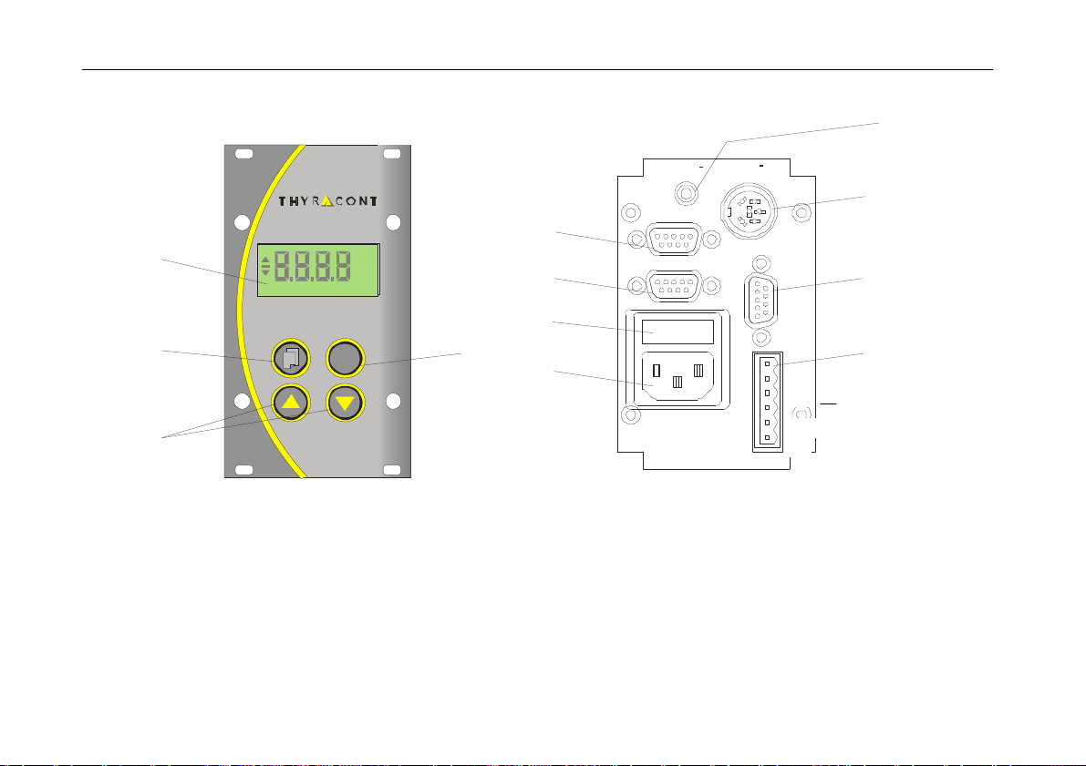
2 Beschreibung
2 Description
2 Description
1 Anzeige
2 Taste Menu
3 Pfeiltasten auf/ab
4 Taste Set
5 Signaleingang 4-20mA VSC
6 Signaleingang 4-20mA VSP
7 Gerätesicherung 0,8AT
8 Netzanschluss
9 Analogausgang 0-10V
10 Signaleingang 0-10V
11 Serielle Schnittstelle RS232
12 Ventilanschlüsse (Vakuum, Belüftung)
1 Display
2 Menu key
3 Arrow keys up/down
4 Set key
5 Signal input 4-20mA VSC
6 Signal input 4-20mA VSP
7 Component fuse 0.8AT
8 Mains connection
9 Analog output 0-10V
10 Signal input 0-10V
11 Serial interface RS232
12 Valve connectors (vacuum, aeration)
1 Affichage
2 Touche Menu
3 Flèches haut/bas
4 Touche Set (réglage)
5 Entrée de signal 4-20 mA VSC
6 Entrée de signal 4-20mA VSP
7 Fusible de l’appareil 0,8 AT
8 Alimentation secteur
9 Sortie analogique 0-10 V
10 Entrée de signal 0-10 V
11 Interface série RS232
12 Raccords de vannes (vide, échappement)
vent
vac
6
1
2
3
4
5
6
1
2
3
4
5
6
1
2
3
4
5
6
3 Installation
3.1 Anschlüsse
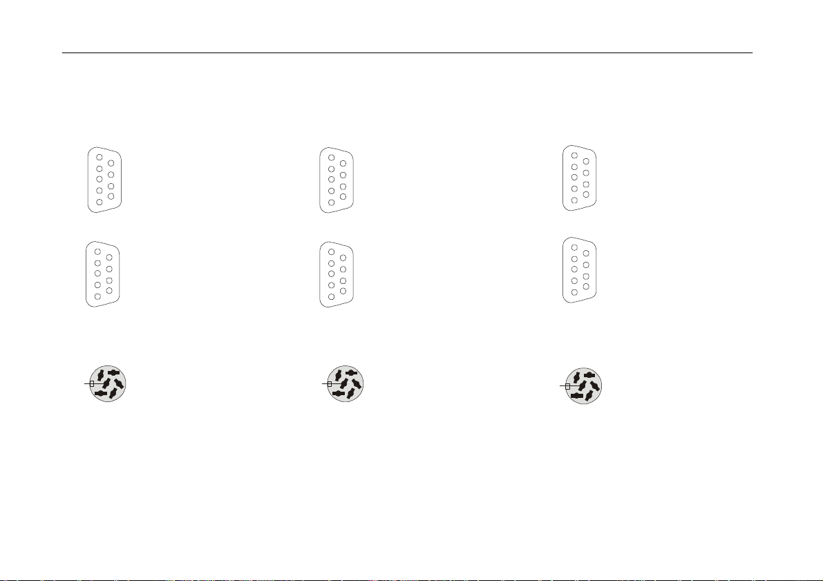
3.1.1 Signaleingänge 4 - 20 mA
Grobvakuum VSC
SubD,
Pin 4:
Pin 7:
Pin 9:
9pol, weibl.
4-20 mA
24 VDC, max. 5W
AGND
Feinvakuum VSP
SubD,
Pin 3:
Pin 7:
Pin 9:
9pol, weibl.
4-20 mA
15 VDC, max. 5W
AGND
3.1.2 Signaleingang 0 - 10 V
Amphenol
Pin 1:
(Pin 2:)
Pin 3:
Pin 4:
Pin 5:
Pin 6:
C91E, 6pol, weibl.
Identifikation
(Analog Out,
0-10V,max.10kΩ
siehe Kap. 3.1.3 !)
Signaleingang,
0-10V
GND
24 VDC, max. 5W
AGND
3 Installation
3.1 Connectors
3.1.1 Signal Input 4 - 20 mA
Rough Vacuum VSC
SubD,
Pin 4:
Pin 7:
Pin 9:
9pole, female
4-20 mA
24 VDC, max. 5W
AGND
Fine Vacuum VSP
SubD,
Pin 3:
Pin 7:
Pin 9:
9pole, female
4-20 mA
15 VDC, max. 5W
AGND
3.1.2 Signal Input 0 - 10 V
Amphenol
Pin 1:
(Pin 2:)
Pin 3:
Pin 4:
Pin 5:
Pin 6:
C91E, 6pole, female
identification
(analog out,
0-10V, max. 10kΩ
see chap. 3.1.3 !)
signal input,
0-10V
GND
24 VDC, max. 5W
AGND
3 Installation
3.1 Connecteurs
3.1.1 Entrées de Signaux 4-20 mA
Vide grossier VSC
SubD,
Pin 4:
Pin 7:
Pin 9:
9 pôles, femelle
4-20 mA
24 VDC, max. 5W
AGND
Vide poussé VSP
SubD,
Pin 3:
Pin 7:
Pin 9:
9 pôles, femelle
4-20 mA
15 VDC, max. 5W
AGND
3.1.2 Entrée de Signaux 0-10 V
Amphenol
Pin 1:
(Pin 2:)
Pin 3:
Pin 4:
Pin 5:
Pin 6:
C91E,
6 pôles, femelle
Identification
(Sortie analog.
0-10V, max. 10kΩ
--> chap. 3.1.3 !)
Entrée de si-
gnaux, 0-10V
Terre
24 VDC, max. 5W
AGND
1
2
3
4
5
6
7
8
9
1
2
3
4
5
6
7
8
9
1
2
3
4
5
6
7
8
9
1
2
3
4
5
6
7
8
9
1
2
3
4
5
6
7
8
9
1
2
3
4
5
6
7
8
9
7
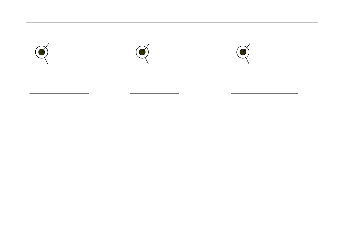
3.1.3 Analogausgang 0 - 10 V
1:
2:
Klinkenbuchse
Analog Out,
0-10V,max.10kΩ
AGND
Analoger Schreiberausgang:
Messumformer Typ 1 (s. Abschn. 4.2.3)
linear, 1 - 1400 mbar entspricht 0 - 10 V
andere Messumformertypen
logarithmisch gemäß Formel (bis max.
1000mbar):
V
out
=
(10V / Dekaden) x ( log(p[mbar]) - exp0 );
Dekaden: Anzahl der vom Messbereich
überstrichenen Dekaden;
p: Druckistwert in mbar;
exp0: Exponent der unteren Messbe-
reichsgrenze in mbar.
3.1.3 Analog Output 0 - 10 V
1:
2:
Jack, female
Analog Out,
0-10V,max.10kΩ
AGND
Analog recorder output:
transducer type 1 (s. chapter 4.2.3)
linear, 1 - 1400 mbar equals 0 - 10 V
other transducer types
logarithmic according to formula (up to
max. 1000mbar):
V
out
=
(10V / decades) x ( log(p[mbar]) - exp0 );
decades: number of decades, which are
covered by measurement range;
p: actual pressure in mbar;
exp0: exponent of the lower limit of the
measurement range in mbar.
3.1.3 Sortie Analogique 0-10 V
1:
2:
Jack, femelle
Sortie analogique,
0-10V,max.10kΩ
AGND
Sortie d’enregistreur analogique:
Convertisseur de mesure type 1 (p. 4.2.3)
linéaire, 1 - 1400 mbar égale 0 - 10 V
Autres types de convertisseur:
logarithmiques selon la formule (á max.
1000mbar):
V
out
=
(10V / Décades) x ( log(p[mbar]) - exp0 );
Décades : nombre de décades couvertes
par la plage de mesure ;
p : pression réelle en mbars ;
exp0 : exposant de la limite inférieure de
mesure en mbars.
2
1
2
1
2
1
8
vac
vent
Beispiel:
Messumformer Typ 2, 1400-0.001mbar
(vgl. Abschnitt 4.2.3)
Istwert: 0.5 mbar
Dekaden: 6
exp0: -3 (f. 1.0e-3mbar)
V
out
=
(10V / 6) x ( log(0.5) - (-3) ) =
4.50 V ;
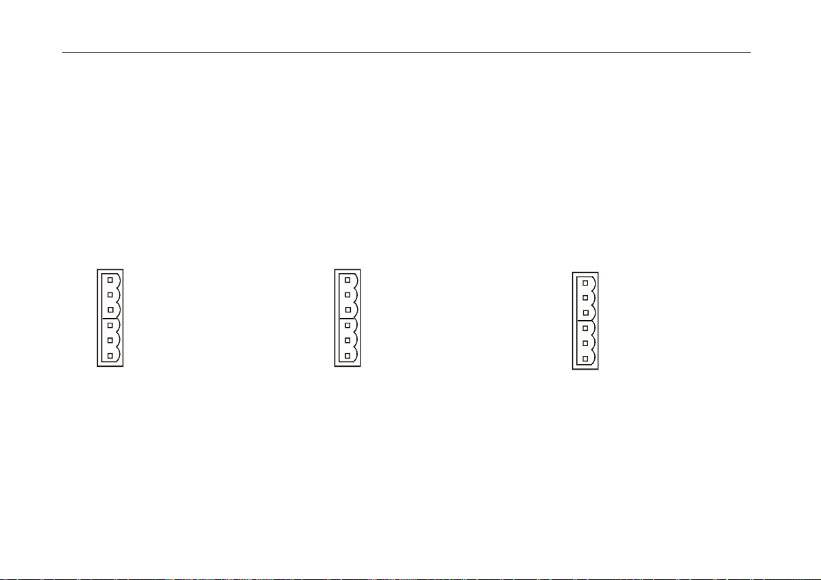
3.1.4 Ventil-Anschlüsse
2x Phoenix Combicon, 3pol
24 VDC auf Masse
+ shield
vac: für Vakuumventil
vent: für Belüftungsventil
Example:
transducer type 2, 1400-0.001mbar (s.
chapter 4.2.3)
actual pressure: 0.5mbar
decades: 6
exp0: -3 (f. 1.0e-3mbar)
V
out
=
(10V / 6) x ( log(0.5) - (-3) ) =
4.50 V ;
3.1.4 Valve Connectors
2x Phoenix Combicon, 3pole
24 VDC to ground
+ shield
vac: for vacuum valve
vent: for venting valve
Exemple:
Convertisseur de mesure type 2,
1400-0.001mbar (p. 4.2.3)
pression réelle: 0.5mbar
décades: 6
exp0: -3 (f. 1.0e-3mbar)
V
out
=
(10V / 6) x ( log(0.5) - (-3) ) =
4.50 V ;
3.1.4 Raccords de vannes
2x Phoenix Combicon,
3 pôles
24 VDC à terre
+ shield
vac: pour vanne à vide
vent: pour vanne d'échappement
vac
vent
vac
vent
vac
vent
vac
vent
vac
vent

9
3.1.5 RS232 Schnittstelle
SubD
Pin 2:
Pin 3:
Pin 5:
9pol, männl.
RxD
TxD
GND
9600 Baud, 1 Startbit, 8 Datenbits,
1 Stopbit, no parity, no handshake.
3.2 Inbetriebnahme
Verbinden sie den oder die benötigten
Messumformer mit den entsprechenden
4-20mA-Eingängen bzw. dem 0-10V
Eingang.
Schließen Sie die Steuerleitungen der
Ventile für Vakuum (vac) und Belüftung
(air) an.
Schließen sie das Netzkabel an.
3.1.5 RS232 Interface
SubD
Pin 2:
Pin 3:
Pin 5:
9pole, male
RxD
TxD
GND
9600 baud, 1 startbit, 8 databits,
1 stopbit, no parity, no handshake.
3.2 Initial Start-Up
Connect the required transducers to the
corresponding 4-20mA resp. 0-10V in-
puts.
Connect the cables for vacuum valve
(vac) and aeration valve (air).
Connect mains power supply.
3.1.5 Interface RS232
SubD
Pin 2:
Pin 3:
Pin 5:
9 pôles, mâle
RxD
TxD
Terre
9600 bauds, 1 bit de démarrage, 8 bits de
données, 1 bit d’arrêt, pas de parité, pas
de protocole de transfert.
3.2 Première Mise en Service
Brancher le ou les convertisseur(s) de
mesure nécessaire(s) à l’entrée 4-20 mA
ou 0–10 V correspondante.
Brancher les câbles de la vanne à vide
(vac) et de la vanne d'échappement (air).
Brancher le câble secteur.
1
2
3
4
5
6
7
8
9
1
2
3
4
5
6
7
8
9
1
2
3
4
5
6
7
8
9

10
4 Bedienung
4.1 Einschalten
Nach Einschalten des VD9 erscheinen
folgende Anzeigen:
-Displaytest (alle Anzeigesegmente
werden 2s eingeschaltet)
-Anzeige Softwareversion
-Anzeige Typ Messumformer
-Anzeige momentaner Druck-Istwert
Das Gerät befindet sich im Messmodus.
Die Druckanzeige erfolgt oberhalb 1 mbar
(Torr...) numerisch, unterhalb in Exponen-
tialdarstellung.
Tastenbeschreibung:
Umschaltung zwischen Mess-
modus und dem Einstellmodus f.
Sollwert, Hysterese bzw. PI-
Parameter und Gasart-Korrektur-
faktor.
Messmodus: Start/Stop-Funktion
für Regelung
Einstellmodus: Bestätigung der
eingestellten Werte
Inkrementieren der Werte im
Einstellmodus
Dekrementieren der Werte im
Einstellmodus
4 Operation
4.1 Power On
After switching the instrument on, the
following display sequenz appears:
-display test (all segments of the LCD
display are activ for 2s)
-display of software release
-display of transducer type
-display of actual pressure
The instrument is in measurement mode.
The display of actual pressure is numeric
above 1 mbar (Torr...) and exponential
below.
Description of keys:
Select between measurement-
mode and set-mode for setpoint,
hysteresis resp. PI-parameters
and gas correction factor.
measurement-mode: start/stop-
funktion for controlling
set-mode: confirmation of adjust-
ed parameter values
Increment parameter values in
set-mode
Decrement parameter values in
set-mode
4 Fonctionnement
4.1 Mise sous Tension
Après mise sous tension du VD9, les
indications suivantes s’affichent :
-test d’affichage (tous les segments
de l’écran s’affichent pendant 2s)
-affichage de la version du logiciel
-affichage du type de convertisseur
-affichage de la pression réelle
L’appareil est en mode mesure.
L’indication de la pression est numérique
au-dessus de 1 mbar (torr,...) et exponen-
tielle en dessous de cette valeur.
Description des touches :
Passage du mode mesure au
mode réglage de la valeur de
consigne, l’hystérèse, para-
mètres PI et facteur de correction
du gaz.
Mode mesure : fonction
Marche/arrêt de la régulation
Mode réglage : confirmation des
valeurs réglées
Incrémentation des valeurs en
mode réglage
Décrémentation des valeurs en
mode réglage
Menu
Set
Menu
Set
Menu
Set
11
4.2 Konfiguration
Um im Konfigurationsmodus Grundein-
stellungen des VD9 zu ändern,
beim Einschalten des Gerätes
die "Set"-Taste gedrückt halten.
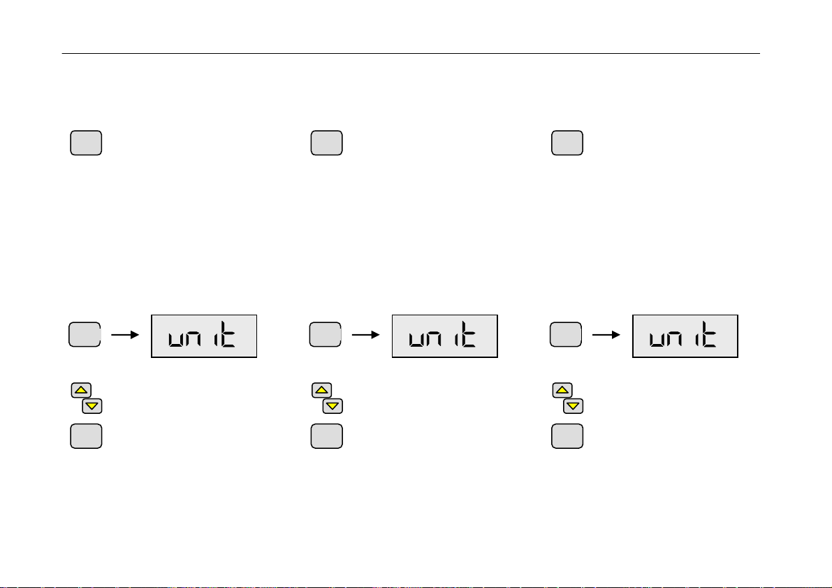
4.2.1 Einheit
Die Einheit der Druckanzeige kann zwi-
schen mbar, bar, hPa, Pa, mTorr und Torr
umgeschaltet werden.
Zum Umschalten der Anzeige-Einheit die
Taste Menu (mehrmals) drücken, bis im
Display "unit" und das Symbol für die
eingestellte Einheit erscheint.
Mithilfe der Pfeiltasten die Ein-
heit umschalten.
Bestätigen mit der Set-Taste.
Rückkehr zum Messmodus.
Erfolgt 5s lang kein Tastendruck oder wird
eine Änderung mit der Taste "Menu"
quittiert, werden die Änderungen verwor-
fen und der ursprüngliche Zustand wieder
angezeigt (Undo-Funktion).
4.2 Configuration
To change basic settings of the VD9 in
the configuration mode,
hold the "Set"-key pressed when
switching the instrument on.
4.5 Unit
The unit of the pressure display can be
switched between mbar, bar, hPa, Pa,
mTorr and Torr.
To select the display unit press Mode-key
(several times) until the display shows
"unit" and the related symbol for the
current unit.
Toggle between various units
using the Arrow-keys.
Confirm with Set-key and return
to measurement mode.
If no key is pressed for 5s or if a change
is quitted with the Menu-key, changes are
lost and the state before the last alteration
is displayed again (undo-funktion).
4.2 Configuration
Pour modifier les réglages de base du
VD9 en mode configuration :
maintenir la touche "Set" enfon-
cée lors de la mise sous tension
de l'appareil.
4.5 Unité
La pression peut être indiquée en mbar,
bar, hPa, Pa, mTorr et Torr.
Pour changer d’unité presser (plusieurs
fois) la touche "Menu" jusqu’à ce que
"unit" s’affiche et que le symbole de l’unité
sélectionnée apparaisse.
Changer d’unité à l’aide des
flèches.
Confirmer avec la touche "Set".
Revenir en mode mesure.
Si aucune touche n’est pressée durant 5
secondes ou si une modification n’est pas
confirmée au moyen de la touche "Menu",
les modifications sont perdues et l’écran
affiche l’état actif avant la dernière modifi-
cation (fonction undo – défaire).
Set Set Set
Set
Menu
mbar
Set
Menu
mbar
Set
Menu
mbar
12
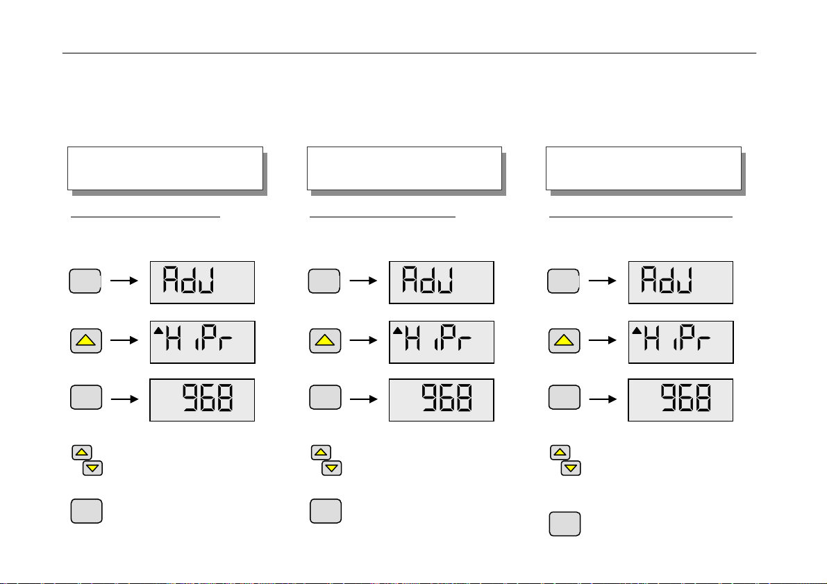
4.2.2 Nachjustierung
Mithilfe des VD9 kann die Messwertan-
zeige bestimmter Messumformer auf
Atmosphäre und/oder Nulldruck abgegli-
chen werden.
Zum Abgleich auf Atmosphäre:
Taste Menu (mehrmals) drücken, bis im
Display "AdJ" erscheint.
Mithilfe der Pfeiltasten den Ta-
gesdruck einstellen (nur bei
Messumformer Typ 1,2,5).
Bestätigen mit der Set-Taste.
Rückkehr zum Messmodus.
4.2.2 Readjustment
With the help of the VD9 the pressure
display of certain transducers can be
readjusted on atmosphere and/or zero
pressure.
Readjustment on atmosphere:
Press Menu-key (mehrmals) until the
display "AdJ".
Adjust atmosphere pressure
using the Arrow-keys (only for
transducer types 1,2,5).
Confirm with Set-key and return
to measurement mode.
4.2.2 Remise au Point
Grâce au VD9, l’indication de pression de
certains convertisseurs peut être réajus-
tée suivant la pression atmosphérique
et/ou le point zéro.
Réajustement suivant atmosphérique :
Presser (plusieurs fois) la touche “Menu”
jusqu’à ce que "AdJ" s’affiche.
Régler la pression atmosphé-
rique à l’aide des flèches (uni-
quement pour les convertisseurs
de type 1, 2 et 5).
Confirmer avec la touche "Set".
Revenir en mode mesure.
Die angeschlossenen Messumformer
benötigen eine Warmlauf-Phase von
mindestens 5 Minuten.
Menu
Set
mbar
Set
Please consider, that connected
transducers need a warm-up of at
least 5 minutes.
Menu
Set
mbar
Set
Attention, les convertisseurs raccor-
dés ont un temps de préchauffage
d’au moins 5 minutes.
Menu
Set
mbar
Set
13
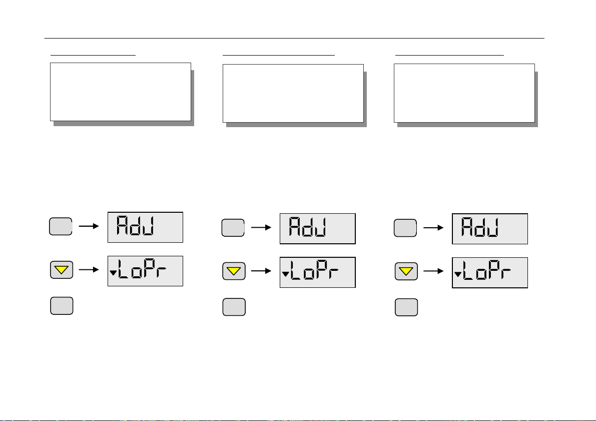
Zum Nullpunkt-Abgleich:
Bei Messumformer Typ 4 ist kein Null-
punktabgleich möglich.
Bei Messumformer Typ 5 ist ein Enddruck
unterhalb 0.1mbar ausreichend.
Taste Menu (mehrmals) drücken, bis im
Display "AdJ" erscheint.
Bestätigen mit der Set-Taste.
Rückkehr zum Messmodus.
Erfolgt 5s lang kein Tastendruck oder wird
eine Änderung mit der Taste "Menu"
quittiert, werden die Änderungen verwor-
fen und der ursprüngliche Zustand wieder
angezeigt (Undo-Funktion).
Readjustment on zero pressure:
For transducer type 4 zero readjustment
is not possible.
For transducer type 5 a zero pressure
below 0.1mbar is sufficient.
Press Menu-key (several times), until the
display shows "AdJ".
Confirm with Set-key and return
to measurement mode.
If no key is pressed for 5s or if a change
is quitted with the Menu-key, changes are
lost and the state before the last alteration
is displayed again (undo-funktion).
Réajustement sur le point zéro:
Convertisseurs de type 4 : ajustement
suivant le point zéro impossible.
Convertisseur de type 5 : une pression
finale inférieure à 0,1 mbar est suffisante.
Presser (plusieurs fois) la touche “Menu”
jusqu’à ce que "AdJ" s’affiche.
Confirmer avec la touche "Set".
Revenir en mode mesure.
Si aucune touche n’est pressée durant 5
secondes ou si une modification n’est pas
confirmée au moyen de la touche "Menu",
les modifications sont perdues et l’écran
affiche l’état actif avant la dernière modifi-
cation (fonction undo – défaire).
Menu
Set
Vor einem Nullpunktabgleich ist sicher-
zustellen, dass der Nulldruck im Rezi-
pienten mindestens eine Dekade
unterhalb der Messbereichsgrenze des
Umformers bzw. der Umformer-
Kombination liegt.
Menu
Set
Before zero adjustment please ensure
that the zero pressure inside your
vacuum chamber is at least one dec-
ade below the measurement range
limit of the transducer resp. the trans-
ducer combination.
Menu
Set
Avant un ajustement suivant le point
zéro, s’assurer que la pression zéro
dans la chambre à vide est inférieure
d’au moins une décade à la limite de
plage de mesure du convertisseur ou
de l’ensemble de convertisseurs.
14
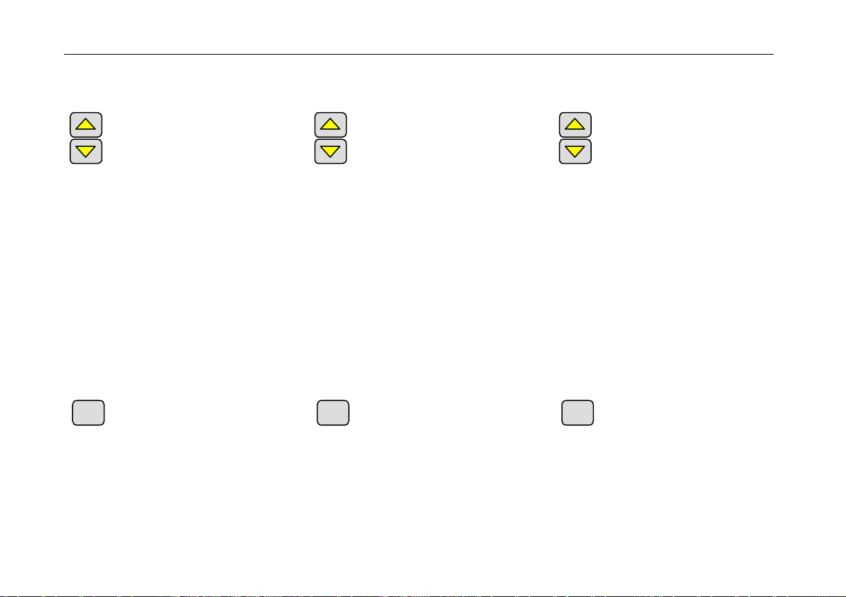
4.2.3 Messumformer-Typ
Es erscheint die Anzeige "tYP*".
Mit up und down Tasten kann
zwischen den verschiedenen
Typen gewählt werden.
Typ1: Grobvakuum-Umformer mit linea-
rem 4-20mA Signal (Anschluss-
buchse VSC), z.B. Thyracont
VSC43MA4 1400-1mbar
Typ2: VSC42MA4 und VSP52MA4
(Grob- und Feinvakuum) 1400-
0.001mbar
Typ3: Typ VSP52MA4 100-0.001mbar
(Anschlussbuchse VSP)
Typ4: VSM72MV / VSH82MV (An-
schlussbuchse 0-10V)
Typ5: Thyracont VSC43MA4 und
VSM72MV / VSH82MV
mit Set-Taste bestätigen.
4.2.3 Transducer Type
The display shows "tYP*".
Using the arrow-keys you can
toggle between various transduc-
er types.
Typ1: rough vacuum transducer with
linear 4-20mA signal (connector
VSC), e.g. Thyracont
VSC43MA4 1400-1mbar
Typ2: VSC42MA4 and VSP52MA4
(rough and fine vacuum) 1400-
0.001mbar
Typ3: VSP52MA4 100-0.001mbar (con-
nector VSP)
Typ4: VSM72MV / VSH82MV (connector
0-10V)
Typ5: Thyracont VSC43MA4 VSM72MV /
VSH82MV
confirm with Set-key.
4.2.3 Type de Convertisseur
L’indication "tYP*" s’affiche.
Il est possible de choisir l’un des
types au moyen des flèches haut
et bas.
Typ1: convertisseur vide grossier avec
signal linéaire 4-20 mA (connec-
teur VSC), par ex. Thyracont
VSC43MA4 1400-1mbar
Typ2: VSC42MA4 et VSP52MA4 (vide
grossier et vide poussé) 1400-
0.001mbar
Typ3: VSP52MA4 100-0.001mbar (con-
necteur VSP)
Typ4: VSM72MV / VSH82MV (connec-
teur 0-10 V)
Typ5: Thyracont VSC43MA4 et
VSM72MV / VSH82MV
confirmer avec la touche "Set".
Set Set Set

15
4.2.4 Ventiltyp Vakuum
Es erscheint die Anzeige "I 0" oder "PI"
und das Symbol "S1".
Mit up und down Tasten kann
zwischen Regelung ohne Rück-
führung (Ein-/Aus-Ventil) und mit
PI-Rückführung (Proportionalven-
til) gewählt werden .
Falls Reglertyp "Pi" gewählt wird, kann
später im Eingabemenu als zusätzlicher
Parameter je Schaltkontakt ein eigener
Regelparametersatz eingestellt werden.
mit Set-Taste bestätigen.
4.2.5 Ventiltyp Belüftung
Es erscheint die Anzeige "I 0" oder "Pi"
und das Symbol "S2".
Mit up und down Tasten kann
zwischen Regelung ohne Rück-
führung (Ein-/Aus-Ventil) und mit
PI-Rückführung (Proportionalven-
til) gewählt werden .
4.2.4 Type Vacuum Valve
The display shows "I 0" or "PI" and the
symbol "S1".
With the arrow keys up and down
you can select between control-
ling without feedback (on/off
valve) or with PI-feedback (steady
valve).
If type "Pi" is selected, an own control-
parameter-set for each switchpoint can be
selected later as additional parameter in
the input menu.
confirm with Set-key.
4.2.5 Type Venting Valve
The display shows "I 0" or "PI" and the
symbol "S2".
With the arrow keys up and down
you can select between control-
ling without feedback (on/off
valve) or with PI-feedback
(steady valve).
4.2.4 Vanne de type à vide
L'écran indique "I 0" ou "PI" et le symbole
"S1".
A l'aide des flèches haut et bas il
est possible de sélectionner la
commande sans retour (vanne
marche/arrêt) ou la commande
avec retour PI (vanne
proportionnelle).
Si le régulateur de type "PI" est sélection-
né, il est ensuite possible de régler, dans
le menu Entrée et comme paramètre
supplémentaire, un jeu de paramètres de
réglage par contact de commande.
confirmer avec la touche "Set".
4.2.5 Vanne de type échappement
L'écran indique "I 0" ou "PI" et le symbole
"S2".
A l'aide des flèches haut et bas il
est possible de sélectionner la
commande sans retour (vanne
marche/arrêt) ou la commande
avec retour PI (vanne
proportionnelle).
Set Set Set

16
Falls Reglertyp "Pi" gewählt wird, kann
später im Eingabemenu als zusätzlicher
Parameter je Schaltkontakt ein eigener
Regelparametersatz eingestellt werden.
mit Set-Taste bestätigen.
4.2.6 Stopfunktion
Im Display wird das Verhalten des
VD9 CV bei Beenden der Regelung per
Stop-Taste angezeigt:
Mit up und down Tasten kann
gewählt werden,
ob nach Beenden der Regelung die Anla-
ge belüftet werden soll ("AEr") oder die
Ventile geschlossen bleiben ("noAE").
mit Set-Taste bestätigen.
If type "Pi" is selected, an own control-
parameter-set for each switchpoint can be
selected later as additional parameter in
the input menu.
confirm with Set-key.
4.2.6 Stop Function
The display shows how the VD9 CV
reacts, when controlling is stopped by
pressing the Stop-key:
With the arrow keys up and down
you can select,
whether the vacuum chamber should be
aerated ("AEr") or valves shoud stay
closed ("noAE"), when controlling is
stopped.
confirm with Set-key.
Si le régulateur de type "PI" est sélection-
né, il est ensuite possible de régler, dans
le menu Entrée et comme paramètre
supplémentaire, un jeu de paramètres de
réglage par contact de commande.
confirmer avec la touche "Set".
4.2.6 Fonction d'arrêt
L'écran indique le comportement du
VD9 CV lorsque la commande est inter-
rompue au moyen de la touche Stop :
Les flèches permettent de
choisir
si la chambre à vide doit être purgée
("AEr") ou si les vannes doivent rester
fermées ("noAE") à l'interruption de la
commande.
confirmer avec la touche "Set".
Set Set
Set
Set Set Set

17
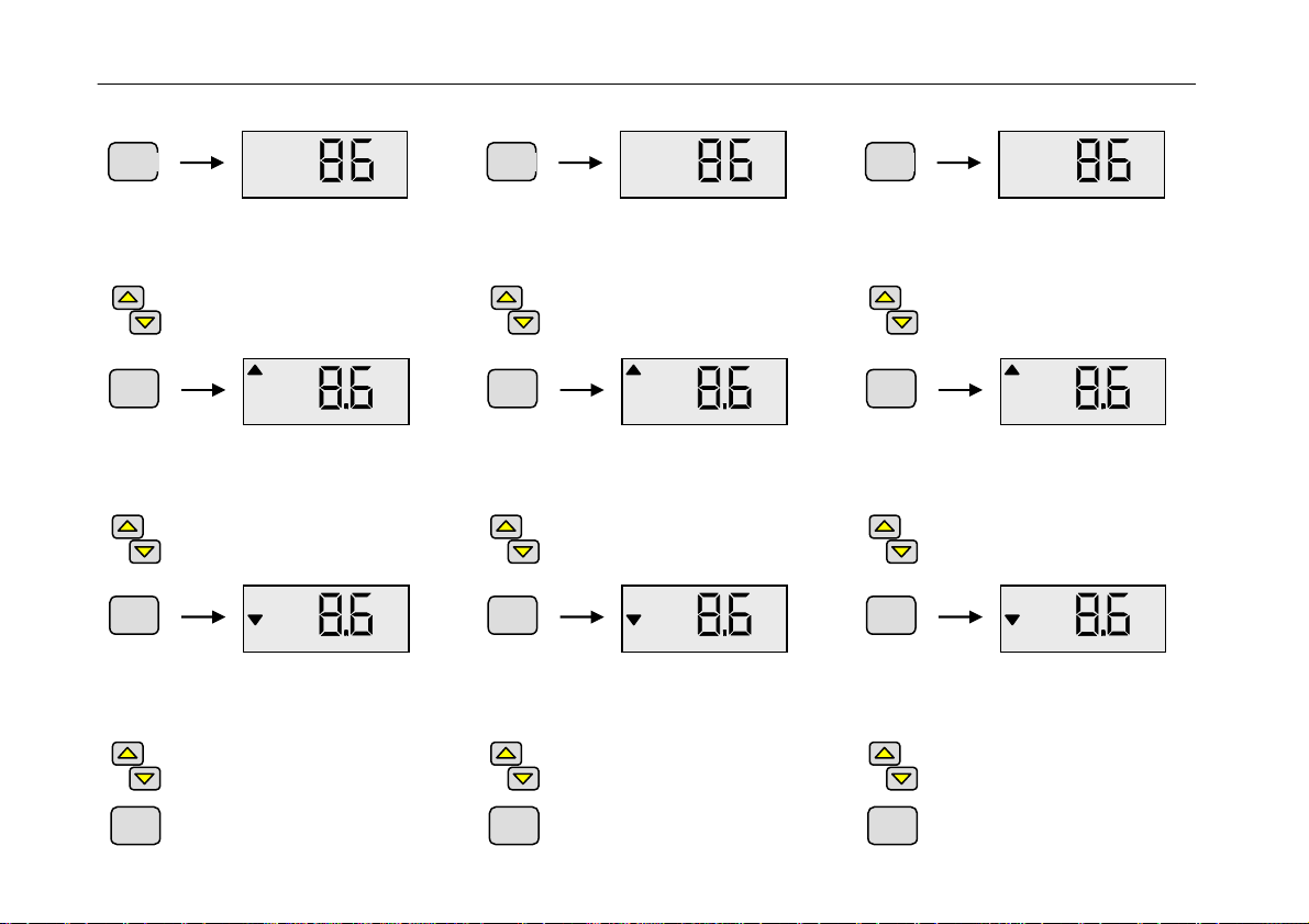
4.2.7 Skalierung Analogausgang
Es erscheint die Anzeige "SCAL".
Mit den Pfeiltasten wird nun gewählt, ob
anschließend der Skalenanfangs- oder
endwert für die Druckausgabe eingestellt
werden soll. Mit der Set-Taste beendet
man den Konfigurations-Modus.
Bei Taste up erscheint in der
Anzeige "S Hi" (Skalenendwert),
bei Taste down "S Lo" (Skalenan-
fangswert).
mit der Set-Taste bestätigen.
Der Skalenend- bzw. anfangswert wird
angezeigt, d.h. der Druckwert, bei dem
10V bzw. 0V ausgegeben werden.
Per Pfeiltasten kann der Skalen-
end- bzw. anfangswert für die
Druckausgabe eingestellt wer-
den.
mit der Set-Taste bestätigen.
Danach erscheint wieder "SCAL" in der
Anzeige und man kann mithilfe der Pfeil-
tasten die Prozedur für den anderen
Skalenwert wiederholen bzw. per Set-
Taste den Konfigurations-Modus been-
den.
4.2.7 Scaling Analog Output
The display shows "SCAL".
Using the arrow-keys you can now
choose to set the upper and lower scale
end for analog pressure output. With the
Set-key configurations-mode is left.
Pressing the up-key the display
shows "S Hi" (upper scale end),
pressing the up-key the display
shows "S Lo" (lower scale end).
confirm with Set-key.
Upper resp. lower scale end is displayed,
i.e. the actual pressure, at which 10V
resp. 0V are put on the analog out.
Adjust upper resp. lower scale
end for analog pressure output
using the arrow-keys.
confirm with Set-key.
After that the display shows "SCAL" again
and the procedure can be repeated for
the other scale end using the arrow-keys.
Pressing the Set-key the configuration
mode is left.
4.2.7 Echelle de Sortie Analogique
l’indication "SCAL" s’affiche. Il est alors
possible de choisir, à l’aide des flèches, la
valeur initiale et la valeur finale d’échelle
pour la sortie de pression. La touche Set
permet de quitter le mode configuration.
Presse la flèche haut: l’indication
"S Hi" (valeur finale d’échelle)
s’affiche ; Presse la flèche bas:
l’indication "S Lo" (valeur initiale
d’échelle) s’affiche.
confirmer avec la touche "Set".
La valeur finale ou la valeur initiale
s’affiche, c’est-à-dire la pression à la-
quelle on a respectivement 10V et 0V au
niveau de la sortie.
Chaque flèche permet de régler
la valeur finale ou initiale de la
sortie de pression.
confirmer avec la touche "Set".
"SCAL" s’affiche à nouveau, il est alors
possible de répéter la procédure de ré-
glage pour les autres valeurs d’échelle ou
de quitter le mode configuration à l’aide
de la touche "Set".
Set
Set
Set
Set
Set
Set

18
4.3 Schaltpunkte
Schaltverhalten "3P" (Dreipunktregler),
Reglertyp "I 0" (Ein/Aus)
Der Schaltpunkt wird in Form eines ge-
meinsamen Sollwertes mit positiver Hys-
terese H1 f. Evakuierung bzw. negativer
Hysterese H2 f. Belüftung eingestellt.
Die Hysteresen liegen asymmetrisch zum
Sollwert. Bei Änderung des Sollwertes
werden die Hysteresen zunächst automa-
tisch über einen prozentualen Zusam-
menhang an den neu eingegebenen
Sollwert adaptiert. Eine anschließende
manuelle Änderung der Hysteresen ist
ebenfalls möglich (Werte werden dabei
auf Plausibilität zum Sollwert überprüft).
Beispiel: Sollwert S = 100mbar
Hysterese H1 = 10mbar
Hysterese H2 = 20mbar
Relais für Evakuierung wird bei 100mbar
deaktiviert und bei 110mbar aktiviert.
Relais für Belüftung wird bei 100mbar
deaktiviert und bei 80mbar aktiviert.
4.3 Switchpoints
Switching Mode "3P" (tri state),
Controller Type "I 0" (without feedback)
The switchpoint is adjusted by one com-
mon setpoint with a positive hysteresis H1
for evacuation and a negative hysteresis
H2 for aeration.
The two hysteresis lie asymmetrical
around the setpoint. When the setpoint is
changed, the hysteresis are adapted
automatically using a constant percentage
ratio. Afterwards a manual adjustemt of
the new hysteresis is, of course, possible
(values are checked according to plausi-
bility).
Example: setpoint S = 100mbar
hysteresis H1 = 10mbar
hysteresis H2 = 20mbar
Relais for evacuation is switched off at
100mbar and switched on at 110mbar.
Relais for aeration is switched off at
100mbar and switched on at 80mbar.
4.3 Points de Commutation
Mode de commutation "3P" (trois points),
régulateur de type "I 0" (Entrée/Sortie)
Le point de commutation est réglé sous
forme d’une valeur de consigne commune
avec hystérèse positive H1 p. l’évacuation
ou négative H2 p. la ventilation. Les
hystérèses sont asymétriques par rapport
à la valeur de consigne. En cas de modi-
fication de la valeur de consigne, les
hystérèses sont automatiquement et
instantanément adaptées à la nouvelle
valeur de consigne suivant un rapport de
pourcentage. Il est également possible de
régler manuellement les hystérèses (la
plausibilité des valeurs par rapport à la
valeur de consigne est alors vérifiée).
Exemple: Val. de consigne S = 100mbar
Hystérèse H1 = 10mbar
Hystérèse H2 = 20mbar
Le relais d’évacuation est désactivé à
100 mbar et activé à 110 mbar.
Le relais de ventilation est désactivé à
100 mbar et activé à 80 mbar.
19
Zum Einstellen des Schaltpunktes:
Taste Menu (mehrmals) drücken, bis im
Display die Symbole "S1" und "S2" er-
scheinen.
Mithilfe der Pfeiltasten den ge-
wünschten Sollwert einstellen.
Bestätigen mit der Set-Taste. Im Display
erscheint die momentan eingestellte
Hysterese H1 für Evakuierung.
Mithilfe der Pfeiltasten Hysterese
H1 einstellen.
Bestätigen mit der Set-Taste. Im Display
erscheint die momentan eingestellte
Hysterese H2 für Belüftung.
Mithilfe der Pfeiltasten Hysterese
H2 einstellen.
Bestätigen mit der Set-Taste.
Rückkehr zum Messmodus.
For adjusting the switchpoint:
Press Menu-key (several times), until the
display shows symbols "S1" and "S2".
Adjust setpoint using the Arrow-
keys.
Confirm with the Set-key. The display
shows the actual hysteresis H1 for
evacuation.
Adjust hysteresis H1 using the
Arrow-keys.
Confirm with the Set-key. The display
shows the actual hysteresis H2 for
aeration.
Adjust hysteresis H2 using the
Arrow-keys.
Confirm with Set-key and return
to measurement mode.
Pour régler le point de commutation:
Presser la touche Menu (plusieurs fois)
jusqu’à ce que les symboles "S1" et "S2"
s’affichent.
Régler la valeur de consigne
souhaitée à l’aide des flèches.
Confirmer avec la touche "Set".
L’hystérèse H1 pour l’évacuation réglée
instantanément s’affiche.
Régler l’hystérèse H1 à l’aide
des flèches.
Confirmer avec la touche "Set".
L’hystérèse H2 pour la ventilation réglée
instantanément s’affiche.
Régler l’hystérèse H2 à l’aide
des flèches.
Confirmer avec la touche "Set".
Revenir en mode mesure.
Set
Set
mbar
S2
Set
mbar
S1
Menu
mbar
S1
S2
Set
Set
mbar
S2
Set
mbar
S1
Menu
mbar
S1
S2
Set
Set
mbar
S2
Set
mbar
S1
Menu
mbar
S1
S2

20
Erfolgt 5s lang kein Tastendruck oder wird
eine Änderung mit der Taste "Menu"
quittiert, werden die Änderungen verwor-
fen und der ursprüngliche Zustand wieder
angezeigt (Undo-Funktion).
Reglertyp "PI" (PI-Regler)
Die Schaltpunkteinstellung erfolgt zu-
nächst wie oben beschrieben über die
Eingabe des Sollwertes und der Schalt-
punktabstände für Evakuierung und
Belüftung. Zusätzlich wird jeweils der
zugehörige PI-Parametersatz gewählt
(Wertebereich von 1 („hart“) bis 8
(„weich“).
Bei Änderung des Sollwertes werden die
Schaltpunktabstände automatisch über
einen prozentualen Zusammenhang an
den neu eingegebenen Sollwert adaptiert.
If no key is pressed for 5s or if a change
is quitted with the Menu-key, changes are
lost and the state before the last alteration
is displayed again (undo-funktion).
Controller type "PI" (PI-feedback)
The switchpoint is adjusted by one com-
mon setpoint -as described above- with
two switchpoint gaps for evacuation and
aeration. Additionally a corresponding set
of PI-parameters is to be selected (value
range 1 "hard" to 8 "soft").
When the setpoint is changed, the
switchpoint gaps are adapted automati-
cally using a constant percentage ratio.
Si aucune touche n’est pressée durant 5
secondes ou si une modification n’est pas
confirmée au moyen de la touche "Menu",
les modifications sont perdues et l’écran
affiche l’état actif avant la dernière modifi-
cation (fonction undo – défaire).
régulateur de type "PI" (régulateur PI)
Le réglage des points de commutation
s’effectue comme indiqué ci-dessus par la
saisie de la valeur de consigne et des
écarts de points de commutation pour
l’évacuation et la ventilation. Il faut en
outre sélectionner le jeu de paramètres PI
correspondant (plage de valeurs de 1
"dur" à 8 "mou").
En cas de modification de la valeur de
consigne, les écarts de points de commu-
tation sont automatiquement adaptés à la
nouvelle valeur de consigne suivant un
rapport de pourcentage.
This manual suits for next models
1
Table of contents
Other Thyracont Measuring Instrument manuals


Popular Measuring Instrument manuals by other brands

Turf-Tec
Turf-Tec Light-DLI-W quick start guide

Milwaukee
Milwaukee LDM 30 Original instructions

GARANT
GARANT 412780 instruction manual

Magnetrol
Magnetrol Thermatel series Measurement Handbook

Flowmetrics
Flowmetrics PA-1001A Series manual

Endress+Hauser
Endress+Hauser Nivotester FailSafe FTL825 operating instructions


