Gason NT8000 Programming manual
COPYRIGHT
Neither this manual or part thereof may be reproduced or published
without the prior permission of AF Gason Pty Ltd
Operators & Parts
Manual
SCARITILL, HYDRATILL
GPN 235554 REV* - 08/07/19

OH&S Compliance Certification
Company Name A.F. GASON PTY LTD
A hazard identification, risk assessment and risk control procedure has been carried out on a representative example of the under men-
tioned product(s) in accordance with the Occupational Health and Safety requirements of all states and territories of Australia and where
found necessary the appropriate risk control measures have been incorporated in the product specifications.
The operator’s manual contains the necessary health and safety information and safety warnings are applied to the product where neces-
sary.
Product Description NT8000 –8m Narrow Transport Width Planter
Models No. or No.’s SNT8000-XX-XXX, HNT8000-XX-XXX
Signed on behalf of the above named company
Name (printed) Tom Mccluskey
Position Design Engineer
Date 03/04/2019
Details of the Unit Assessed for the Purpose of Compliance
Model No. SNT8000-32-250
Serial No. 235555-00001
Date of Inspection 18/01/2019
Location of Inspection ARARAT, VICTORIA

Contents
Safety .........................................................................................................................................5
NT8000 Specifications................................................................................................................8
Transport Dimensions................................................................................................................9
Unloading From Transport.......................................................................................................10
Assembly..................................................................................................................................10
Operating the NT8000 .............................................................................................................12
Connection/Disconnection ..................................................................................................13
Tractor Requirements..........................................................................................................13
ScariTILL Operation..............................................................................................................13
HydraTILL Operation............................................................................................................13
Road Transportation............................................................................................................14
Depth Control Circuit ...........................................................................................................14
Wing Fold Circuit..................................................................................................................15
HydraTILL Circuit..................................................................................................................15
Pre - operation Checklist......................................................................................................16
Maintenance............................................................................................................................17
10 Hours or Daily..................................................................................................................17
100 Hours or Weekly ...........................................................................................................17
500 Hours or Seasonally ......................................................................................................17
Cleaning and Storage ...........................................................................................................17
Tyre Care..............................................................................................................................18
Bush Replacement ...............................................................................................................18
Wheel Bearing Maintenance ...............................................................................................18
Hard Facing Keech Adaptor .................................................................................................19
Replacement of Keech Adaptor...........................................................................................19
ScariTILL Tine Assembly .......................................................................................................20
Nordon Cylinders .................................................................................................................21
Owner Acknowledgement .......................................................................................................25
Spare Parts...............................................................................................................................27
SNT8000 & HNT8000 Models ..............................................................................................27
ScariTILL (Spring) Tine Assembly..........................................................................................28
HydraTILL (Hydraulic) Tine Assembly...................................................................................30
Shank Options......................................................................................................................32

NT8000 Assembly.................................................................................................................34
Centre Frame Assembly.......................................................................................................36
Left Wing Assembly..............................................................................................................38
Right Wing Assembly ...........................................................................................................40
Depth Indicator Kit...............................................................................................................42
Decals...................................................................................................................................43
Optional Seeder Mount Kit –1200 Series IM2 Seeder........................................................44
Optional Rear Tow Hitch Kit - 1700 Series Seeder...............................................................44
Optional Rear Tow Hitch Kit - Controlled Traffic Castor......................................................45
Optional Rear Tow Hitch Kit - Controlled Traffic Steerable.................................................46
Stub Axle Assembly..............................................................................................................47
Hydraulic System –Wing Fold .............................................................................................48
Hydraulic System –Depth Control.......................................................................................50
Optional Hydraulic Hitch Leveller ........................................................................................52
Hydraulic Hose Clamp Assembly..........................................................................................53
HydraTILL Plumb Kit –250mm Spacing ...............................................................................54
Layout - 178mm Spacing –45 Tines ....................................................................................56
Layout - 250mm Spacing –32 Tines (Optional Presswheels Shown) ..................................57
Layout - 308mm Spacing –26 Tines (Optional Presswheels Shown) ..................................58

Introduction
1
AF Gason Pty Ltd (Gason) is an Australian
owned family business operating from within
rural Victoria. The Gason Company has been
servicing the needs of rural Australians for
over 70 years. We operate through a local
dealer support network that spans the coun-
try. Gason would like to thank you for pur-
chasing your Australian made tillage imple-
ment, and trust that you will have many years
of trouble free service.
The NT8000 is an 8m wide planter that utilizes
five 100x100x9mm toolbars welded in a ro-
bust frame designed to fold up to 3.5m wide
for road transport. The NT8000 provides a
versatile platform that can be optioned with
the HydraTILL hydraulic tine assembly and the
ScariTILL spring tine assembly as well as the
Parallelogram and Toolbar Mounted Press
Wheel Assemblies. The NT8000 accommo-
dates 2m Controlled Traffic practices with its
2.0m wheel centers and 8.0m effective work-
ing width.
A) HydraTILL Tine with optional Parallelogram
Presswheel.
B) ScariTILL shown with optional Frame Mounted
Presswheel.
Gason ScariTILL and HydraTILL tines accept a
50mm x 25mm vertical shank with upper
holes enabling vertical adjustment. These tine
assemblies have been proven over many
years of use. Various points and sowing boots
are available.
Ideally coupled to a Gason Air Seeder as a
minimum till planter, the NT8000 can also be
used for conventional weed kill/soil prepara-
tion. With various tools and options the
NT8000 can be setup to perform a variety of
tasks depending on specific agronomic re-
quirements. These may include:
Conventional cropping: Multiple cultivations
before sowing for weed control and seed bed
preparation.
Direct drilling: One pass sowing system with
wide or full cut points for some soil disturb-
ance.
Minimum-till: Sowing systems aimed at mini-
mizing soil disturbance and retaining crop res-
idues.
2m Controlled Traffic: 4 wheels are mounted
inside the frame at 2.0m centres.
The NT8000 is equipped with 4 single 400/60-
R22.5 flotation tyres and wheel mounted in-
side the frame, which ensure easy turning and
contouring, and maintain tracking. The wheels
are positioned to obtain maximum clearance
for working tools and also cater for tight turn-
ing. The frame has been designed to maximize
stubble flow and provide uniform finishes
while accommodating multiple layouts.
A B
Introduction
2
Caution: This implement has been developed
for maximum residue/stubble flow. If work-
ing around hillsides, pairing of rows may oc-
cur.
Caution: Correct seed depth is critical to suc-
cess. Check seeding depth regularly during
sowing.
Caution: Fitment of additional attachments
such as anhydrous ammonia tanks and
prickle chains, which may place significant
loads on the frame, will void warranty on the
frame and any related components. Approved
attachments include, toolbar mounted press
wheels, parallelogram assemblies as well as
Gason’s range of mounted and trailed air
seeders. If unsure as to the warranty implica-
tions to any attachment or modification that
you wish to make to your NT8000, consult
your local authorized Gason Dealer.
To The Dealer
Assembly and proper installation of this prod-
uct is the responsibility of the Gason dealer.
The dealer and owner/operator must com-
plete & sign the Installation and Warranty
Registration Form included with this manual
before releasing the Implement to the new
owner.
Purchaser copy to be supplied to owner.
Dealer copy to be retained by dealer
Company copy to be returned to Gason.
In addition, the dealer must complete the
Dealer Pre-Delivery & In-field Commissioning
Check List included within this manual.
Gason strongly recommend a risk assessment
be carried out prior to the machine being op-
erated to ensure the operators fully under-
stand the dangers involved in the operation of
the Gason Tillage Implement.
About this Manual
This manual endeavors to provide the owner
with a complete understanding of the NT8000
implement’s safety, assembly, maintenance
and operation including the processes re-
quired to obtain the highest level of perfor-
mance possible.
Caution: It is of the utmost importance that
the owner/operator read this manual, and
any other literature that has been supplied
with the machine, to ensure a safe and trou-
ble free operation.
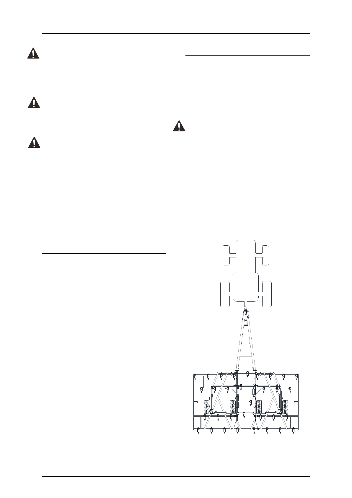
References to the left and right hand sides of
the Implement are from the rear of the ma-
chine looking forward in direction of travel as
shown.
LEFT RIGHT
Introduction
3
To The Owner
Caution: Read & understand this manual
before operating your Gason Implement.
The information presented will prepare you to
operate your machine in a more efficient and
safer manner.
This manual should ideally be kept in its pro-
tective satchel and stored with the machine.
Replacement manuals are available upon re-
quest from Gason or online at
www.gason.com.au. Replacement “holders”
are available through your nearest dealer.
The manual includes an Installation and War-
ranty Registration Form, of which, requires
the dealer & the owner/operator to sign. The
Purchaser copy of this form is to remain with
the owner/operator.
Caution: Ensure you carry out, and keep up
to date, a Risk Assessment. All operators
must read the manual carefully and become
acquainted with all the adjustments and oper-
ating procedures before attempting to oper-
ate.
The Implement you have purchased has been
carefully engineered and manufactured to
provide dependable and satisfactory use
when operated & maintained in line with this
manual. Like all mechanical products, it will
require routine cleaning, upkeep and mainte-
nance. Lubricate the implement as specified in
this manual. Observe all safety information in
this manual and obey all safety decals located
on the machine.
Please be aware that in an effort to bring you
the best products Gason are always imple-
menting continuous improvements that may
change the designs and specifications of the
implements. In doing this, Gason, together
with its dealers and distributors, are under no
obligation to implement such changes, free of
charge, on any previously delivered machines.
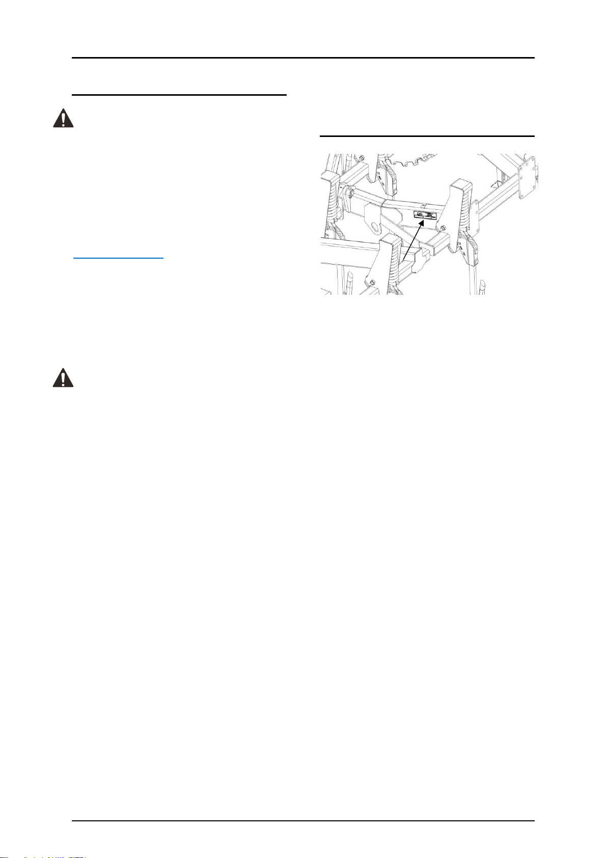
Machine Record
Serial No. Tag Located at left hand rear of cen-
tre frame.
Tine Spacing: __________________________
Number of Tines:_______________________
Serial Number: ________________________
Model: _______________________________
Date Purchased: ________________________
Owner Name: __________________________
Owners Address: _______________________
_____________________________________
_____________________________________
Options Fitted: ________________________
_____________________________________
_____________________________________
_____________________________________
_____________________________________
SERIAL No. TAG

Introduction
4
Dealer Pre-Delivery & In-Field Commissioning Check List
The following must be carried out upon machine delivery to customer
Tick to confirm action
√
Customer has ensured that Machine is correct for the required application.
Customer has checked tractor specification to ensure machine is suited to tractor.
Customer has checked all items are received as per order.
Machine Assembled Correctly as per Operators Manual instructions.
Check Wheel Nuts for correct torque (refer maintenance section)
Tyre Pressures are correct as recommend.
Grease all grease nipples; hinges and wheel assembly pivots.
Check for Hydraulic Oil leaks.
Air purged from Hydraulic Circuits and tractor’s hydraulic oil level is OK.
Ensure Depth Control cylinders are phasing correctly (synchronized).
Ensure Machine is level front to rear at working depth.
Ensure Machine is level across the width.
Ensure lock nuts on depth control adjustment are locked tight.
Check for correct tractor to tow bar connection.
Implement safety chain fitted to tractor.
Ensure all shanks and press wheels set at consistent settings across machine, (If prac-
tical set machine to operator’s initial operation settings).
Check Air Seeder Distribution for kinks and obstruction through all working ranges
(where applicable).
Check row spacing is correct. (At initial operation, drive in straight line, lightly scratch-
ing machine along flat ground. Measure distance between marks).
Owner has viewed the Operators Manual.
Owner instructed on correct maintenance and safe operation of machine.
Owner and operators instructed on phasing cylinders depth stop use and
Owner and operators instructed to fully extending wing fold cylinders when operating.
Owner has agreed to train all operators in the safe use of the machine.
Pre delivery and in field commissioning by:
NAME:
DATE:
SIGNED:

Safety
5
Safety
Gason rate operator Safety as one of the high-
est priorities when designing new features and
machines. Every effort is taken to consider the
end user and the safety risks they may face.
Accidents can Disable & Kill
Accidents are Costly
Accidents Can be Avoided
Safety Alert Symbol
The Safety Alter Symbol
means:
ATTENTION!
BECOME ALERT!
YOUR SAFETY IS INVOLVED!
The Safety Alert Symbol identifies important
safety messages applied to the Implement in
this manual. When you see this symbol, be alert
to the possibility of injury or death. Follow the
instructions provided on the safety messages.
Throughout this Manual the Safety Alert Symbol
will be seen followed by one of the words.
Signal Words
DANGER: indicates an imminently hazardous sit-
uation that, if not avoided, WILL result in death
of serious injury if proper precautions are not
taken.
WARNING: Indicates a potentially hazardous sit-
uation that, if not avoided, COULD result in
death or serious injury if proper precautions are
not taken
CAUTION: Indicates a potentially hazardous situ-
ation that, if not avoided, MAY result in minor or
moderate injury if proper precautions are not
taken, or, serves as a reminder to follow appro-
priate safety practices.
Safety
6
General Safety
Whilst great care and every effort have been
made by Gason to provide a machine to the
highest possible safety standards, tillage imple-
ments by their nature are potentially danger-
ous.
Read and understand this manual and the man-
ual of the tractor towing the implement. Know
your machine and its limits and operate within
them. If in doubt, ASK!
Be Prepared
In the event of an emergency it is best to be
prepared. Gason recommend whilst operating
the Implement, a fire extinguisher and first aid
kit should be readily available in the event that
they might be required.
Safety Decals
All Gason Tillage Implements are provided with
a complete set of decals which include im-
portant safety information and are required to
ensure the machine complies with the relevant
work safe regulations. Every effort should be
made to ensure the decals are legible at all
times. Any decal which can be seen to be worn
or can no longer be read should be replaced.
For a detailed list of Decals and their positions
on the machines refer to the Parts section of
this manual.
Safety Rules
Danger: Do not operate the tractor or Im-
plement until you have fully read and com-
pletely understand this operator’s manual, your
tractors operator’s manual, and all safety mes-
sages found within these manuals, on the prod-
ucts, or other included material.
Warning: Ensure all operators are properly
instructed on the operation of the machine and
position of controls. Do not allow anyone to oper-
ate the machine without proper instruction.
Warning: Know your controls and how to
stop the machine quickly in an emergency.
Warning: Keep hands and body away
from pressurized lines. Wear safety glasses to
protect eyes. Hydraulic fluid (oil) under pressure
can easily penetrate the skin, ensure all opera-
tors and service personnel are aware that if hy-
draulic fluid (oil) penetrates the skin it will need
to be surgically removed. Failure to do so may
result in serious injury or death.
Danger: Stand clear when folding or un-
folding wings.
Caution: Check that all hardware is tight
and properly installed. Refer Assembly Torque
table.
Caution: Ensure the implement is
properly attached, adjusted and in good work-
ing order before operating the machine.
Caution: Remove any debris that has ac-
cumulated on the implement or tractor.
Danger: DO NOT allow persons to ride on
machine during operation or transport.

Safety
7
Caution: For transportation on public
roads the operator must ensure that the tractor
and Implement complies with current state and
federal laws and must strictly adhere to all road
traffic regulations.
Warning: Use Extreme care and reduce
ground speed on slopes and rough terrain.
Warning: DO NOT transport implement in
excess of 20km/h.
Warning: DO NOT exceed 10° roll angle
with wings folded.
Caution: Always double check before re-
versing machine.
Danger: Never place any part of the body
underneath tines. Hydraulic systems can
“creep” (i.e. slowly lower). Any movement of
the control levers can cause the implement to
drop or move unexpectedly causing severe in-
jury or death.
Warning: DO NOT adjust Hydraulic fitting
while under pressure. Ensure pressure is re-
leased using tractor’s hydraulic system before
adjusting or disconnecting Implement.
Warning: Never remove hydraulic hoses or
ends with machine elevated. Relieve hydraulic
pressure before disconnecting hydraulic hoses
or ends.
Caution: Maintain sufficient hydraulic fluid
levels to ensure air is not introduced into the
system.
Caution: Keep all connectors clean for pos-
itive connections.
Caution: Ensure all fittings and hoses are
in good condition.
Disclaimer
Gason accepts no responsibility or liability for any losses, injuries or damages
that may result from failing to observe these safety rules and the safety decals
on the Implement.

Specifications
8
NT8000 Specifications
Machine Dimensions
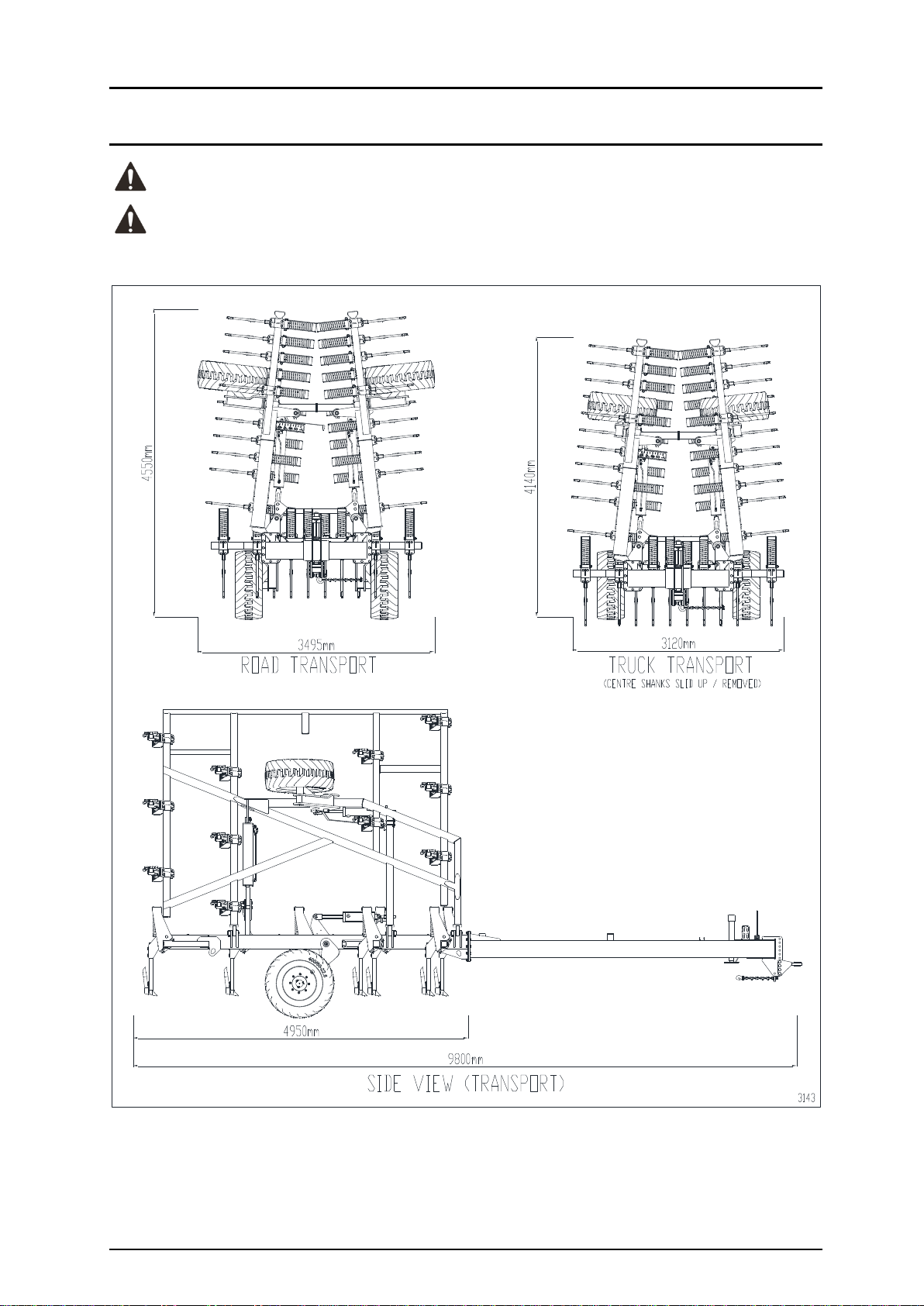
Overall Length
9.80m
Overall Unfolded Width
8.10m
Frame Depth (front to rear)
4.20m
Overall Road Transport Width
3.495m
Overall Road Transport Height
4.55m
Road Clearance:
250mm (10”)
Max. Recommended Working Depth:
150mm (6”)
Overall Weight
8.0t **
**Approximate weight only, varies depending on configuration and attachments
Tine Spacing
Number of Tines
Effective Working Width
178mm (7”)
45
8.0m
250mm (10”)
32
8.0m
308mm (12”)
26
8.0m
No. of Toolbar Rows:
5
Toolbar Spacing:
1.0mtyp.
Toolbar Section:
100 x 100 x 9.0mm RHS Grade 450
Drawbar Section:
150 x 250 x 6.0mm RHS Grade 450
ScariTILL:
Breakout Force
180kg (400lbf)
245kg (540lbf)
Underframe Clearance
760mm to 660mm (30” to 26”) in 12.5 mm (½”) increments.
Tine Jump
350mm (13.8”)
HydraTILL:
Breakout Force Hydraulic
140kg to 310kg (310lbf to 680lbf)
Underframe Clearance
760mm to 660mm (30” to 26”) in 12.5 mm (½”) increments.
Tine Jump
350mm (13.8”)
Tyres:
400/60-22.5 18PLY Tubeless Floatation Tyre
Wheel Centre Width:
2.0m (2m controlled traffic)
Hydraulic Hoses (depth & wing fold)
½’’ I.D. SAE100R2 hose (non-skive)
Maximum Road Transport Speed:
20km/h
Specifications
9
Transport Dimensions
Caution: Dimensions will vary depending on the machine configuration.
Warning: The machine can be configured such that the road transport width exceeds 3.5m.

Unloading and Assembly
10
Unloading From Transport
Because of the compact nature of the
NT8000, most machines will be delivered as-
sembled ready to be towed off the truck. If
not assembled or unable to be towed off
machines must be lifted by approved over-
head lifting gear and licensed operators.
Warning: Only qualified personnel are
to be involved with the lifting of machine.
Bystanders must remain clear at all times.
Danger: Ensure that all lifting equip-
ment is in good condition and has the ca-
pacity to lift the load. Do not lift unless the
weight is known or a reasonable assumption
of weight is determined.
Note: Gason dispatch department measure
and record the load & other lift information
on a Crane Lift form*. A copy of this form is
given to the truck driver for use at the un-
loading end.
If lifting points are around the RHS frame
use soft slings. Avoid excessive paint dam-
age, if chains must be used, ensure paint-
work is protected.
Assembly
If the NT8000 is transported partially disas-
sembled, items that may require assembly
are as follows:
Fitment of wheels and tensioning to cor-
rect torque. Wheels may have been re-
moved depending on transport height
required.
Fitment of pull.
Fitment of tines / press wheels to the
marked position.
Shank Fitment.
Reconnection of hydraulic hoses, secur-
ing hoses in clamps and priming hydrau-
lic circuits.
Fitment of implement depth indicator.
Ground tool Fitment.
Touchup of paint work if required.
Wheel Fitment - If wheels have been re-
moved for transport, loosely mount wheels
on hubs. Be Gentle. Avoid damage to
threads. Tighten all nuts firmly then proceed
to torque each wheel nut to 350N.m. Alter-
nating sides across stud pattern when tight-
ening up nuts.
Fitting Pull –the pull may be removed for
transport. Using a crane, position & fit the
drawbar to the front of the centre frame us-
ing the bolts provided i.e. M20 Grade 8.8
bolts and Class 8 Nyloc nuts. Torque bolts to
335 N.m. Lower the jack to support the
front of the drawbar and fit safety tow
chain.
Tine Fitment - Tine location decals (arrows)
should be fitted to the toolbar to indicate
the tine locations for tines/row units not fit-
ted or not fitted in the correct location.
Upon fitment, ensure the correct hardware
is used i.e. M20 Grade 8.8 bolts and Class 8
Nyloc nuts. Secure the four fasteners in
stages to pull up the tine evenly and
squarely onto the toolbar.
Caution: Assembly torque settings
are critical to ensure tine assemblies remain
secure to the toolbar at all times. Torque to
335 N.m. Confirm this setting with a good
quality torque wrench.
Shank Fitment - Fully raise implement, fit
the tine shanks to the upper tine assem-
blies. Ensure positioning pins are in the
same hole in both the shank and the pivot
bracket to the tine tower. Ensure the rear
M20 set screws are tightened up hard
against the shank and the locking nut is then
tightened.
Unloading and Assembly
11
Hydraulic Circuit - In setting up the hydrau-
lic circuit cylinders should be correctly lo-
cated and aligned. Hoses must be con-
nected to complete the correct circuit as per
schematics provided in the parts section of
this manual. Cleanliness of the system must
be maintained. When securing the hydraulic
hoses to the frames ensure that sufficient
slack is provided in areas where a pivot joins
members or the connection is to a moving
component.
Depth Control - The depth control circuit
consists of master/slave phasing cylinders in
series. Generally the depth control system
will be factory primed.
Wing Fold - A hydraulic circuit is employed
to fold the wings from the working position
for transport or storage. The wing fold cir-
cuit consists of a two double acting cylinders
connected in parallel. Generally the wing
fold system will be factory primed.
HydraTILL Circuit –If configured as a Hy-
draTILL an extra circuit is added including an
accumulator for tine breakout. Generally
the HydraTILL system will be factory primed.
Caution: Maintain a close watch on
tractor oil level and top-up with new clean
oil as required. Observe closely as too low
an oil level may introduce more air into the
system.
Warning: The presence of air in the
hydraulic circuits will cause the implement
to operate erratically and is potentially very
dangerous when folding wings or transport-
ing the implement.
Ground Tool Fitment - There are a selection
of aftermarket ground engaging tools availa-
ble to suit the range of shanks. Selection of
the most appropriate ground tool will de-
pend on your agricultural practices, ground
conditions and sowing boot design.
Torque Specifications
Caution: Torque values listed on the
following page should be used as a guide
only. If a different torque value or tighten-
ing procedure is specified for a specific ap-
plication, do not use these values.
Refer to the Parts section for proper grade
and length of bolts for replacement parts.
Do not replace Nyloc nuts with nuts and
spring washers. Replace all parts with origi-
nal specified parts only (note fastener
grades).
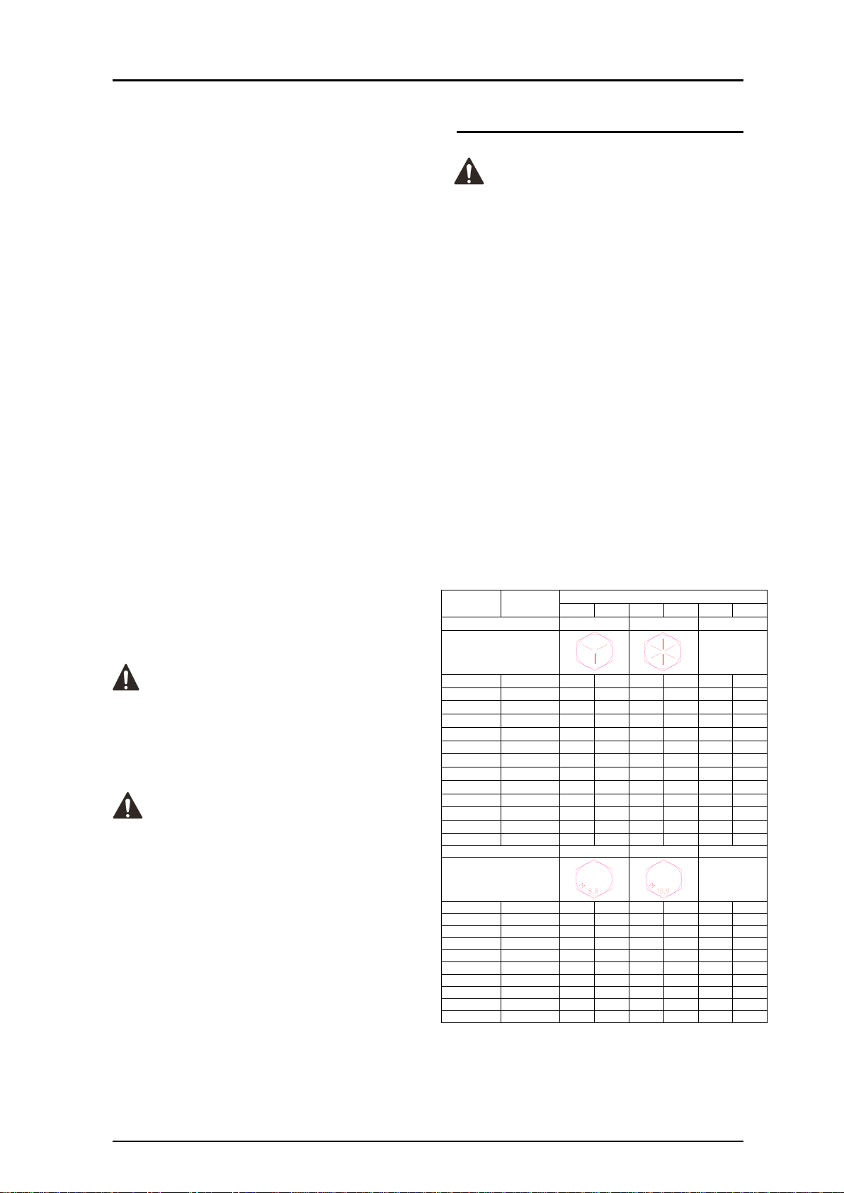
The following torque figures are those rec-
ommended for zinc plated, lightly oiled
bolts. Recommended assembly torques may
be obtained by multiplying the torque fig-
ures in the table below by:
0.78 –for degreased zinc plated bolts.
1.10 –for black oxide finished bolts.
lbf.ft Nm lbf.ft Nm lbf.ft Nm
7/16 UNF 43 59 60 82 - -
7/16 UNC 39 53 54 74 - -
1/2 UNF 67 91 94 128 - -
1/2 UNC 59 81 83 113 - -
5/8 UNF 135 184 186 253 - -
5/8 UNC 117 159 165 224 - -
3/4 UNF 235 319 325 441 - -
3/4 UNC 210 285 290 394 - -
7/8 UNF 370 502 520 706 - -
7/8 UNC 335 455 470 638 - -
1UNF 550 746 775 1052 - -
1UNC 505 685 710 963 - -
M10 1.5 29 40 41 56 - -
M12 1.75 51 70 73 100 - -
M16 - - - - - 170 231
M16 2.0 126 171 180 245 - -
M18 1.5 - - - - 254 345
M20 1.5 - - - - 376 510
M20 2.5 247 335 351 477 - -
M22 1.5 - - - - 475 645
M24 - - - - - 500 679
M24 3.0 425 577 608 825 - -
Head Markings
(Manufacturers marks
may vary)
Recommended Assembly Torque
8.8
10.9
Wheel Stud
Metric Grade Number
S.A.E Grade Number
5
8
Size
Thread
Pitch
Wheel Stud
Head Markings
(Manufacturers marks
may vary)

Operation
12
Operating the NT8000
The design of your NT8000 provides flexibility
in tine spacings and layouts, working depths,
ground engaging tools and provision for a
multitude of attachments, allowing its use for
more than just one application or practice. Re-
gardless of the practices being employed,
there are a number of general rules that
should be followed when working the NT8000
to ensure maximum working life.
1. Whenever starting or stopping, the tines
should always be out of the ground. When
commencing work, move off slowly and
lower the implement to the required
depth; then increase to the desired work-
ing speed (up to a maximum recom-
mended speed of 10 km/h).
2. Do not turn too sharply whilst tines are in
the ground as this will place excessive
loads on the tines, ground tools and
frame. Tines must be raised out of the
ground when turning at headlands or in
other tight situations.
3. Do not work with the wings folded,
whether partially or completely. Ensure
wing fold cylinders are always fully ex-
tended when operating to allow wings to
float up and down.
4. Become familiar and aware of the limita-
tion of the implement and work within
these limits. It is your responsibility to as-
sess your specific application and deter-
mine the risks involved and appropriate
action.
5. Upon selecting the desired working depth,
set the depth stop mechanism to control
the height as per depth control section of
this manual. Once set, work implement
for approximately 100m and check depth
consistency. Adjust as necessary.
6. Whilst working, regularly observe the en-
tire implement for any blockages of mud,
stubble or any other obstructions.
7. Avoid working on excessively steep slopes
or rocky terrain.
8. The tines are designed to trip when en-
countering an obstacle. The implement
should never be worked with the tine
shank constantly laying back from vertical
or jumping. This may cause premature,
abnormal wear of the tine assembly.
SUCH WEAR WILL NOT BE COVERED UN-
DER WARRANTY.
Working in this manner will also increase
the loads placed on the implement frame
and increase tractor fuel consumption. In
addition, the correct ground tool working
angle and consistent depth control will
not be maintained. If such a situation per-
sists, the load on the tine must be re-
duced by:
- decreasing ground speed.
- reducing working depth.
- replacing ground tools with design that
produces less draft.
- shortening the tine shank by sliding up
the casting.
- delay working until more suitable soil
conditions prevail.
9. Conduct (or have your dealer conduct)
pre-season checks on your implement as
per “Maintenance” section of this manual.
Replace pins and bushings immediately
where excessive wear is observed to pre-
vent damage to housings.
10. Inspect implement and ground tools for
damage daily. Grease and Maintain as per
the “Maintenance” section of this manual.
11. It is recommended that the machine is
stored undercover when not in use. The
lifespan of hydraulic hoses, paintwork and
distribution kit components is dramati-
cally reduced when left outside for ex-
tended periods of time.

Operation
13
Connection/Disconnection
Ensure the implement is always discon-
nected/connected on flat, level ground.
When connecting the NT8000;
Ensure a suitable drawbar pin is used with
a retaining clip fitted.
Ensure hydraulic couplings are clean and
not damaged.
Install a suitably rated implement safety
tow chain (supplied with machine), from
drawbar to a secure location on the trac-
tor.
Ensure hydraulic hoses and electrical
wires are sufficient in length and if neces-
sary, tied up to prevent catching/pinching
as the tractor and implement articulate.
Lift jack to its uppermost setting before
moving.
When disconnecting the NT8000 close both
safety lockout valves and float all hydraulic
circuits before unplugging from tractor.
Tractor Requirements
Ensure your tractor is compatible with the
NT8000 implement and seeder combination.
Check the following:
Does the tractor have sufficient power to
pull this combination in the field? Gener-
ally you will require between 5-9hp per
tine and 8hp per ton of seeder.
Does the tractor have sufficient weight to
tow the combination safely on public
roads?
Does the tractor of have sufficient hydrau-
lic capability? ScariTILL models require 2
sets of remotes, HydraTILL models require
3 sets of remotes. This is in addition to
seeder requirements.
Important: These are only rough guidelines;
hills and soil conditions can have a large im-
pact on tractor power requirements.
Note: The implement hitch has been designed
to suit a Category 4 drawbar or Category 3
drawbar (2-1.5” dia. pin). Tractors with Cate-
gory 1 or 2 drawbars should not be used.
ScariTILL Operation
The ScariTILL Tine utilizes a spring
as the break out mechanism. The
tine’s breakout is nominally 180kg
(400lb) or 245kg (540lb) depend-
ing on the model. The ScariTILL’s
tine shank height can be adjusted
vertically in 12.5mm (1/2”) incre-
ments.
Digging depth is adjusted using
the frame’s depth control system.
Important: M20 set screws secur-
ing the shank may need retightening upon ini-
tial bedding in.
Note: The tine breakout force increases as the
underframe clearance (UFC) is reduced.
HydraTILL Operation
The HydraTILL Tine utilizes a
hydraulic cylinder as the break
out mechanism. The tine’s
breakout can be varied from
nominally 140 to 310kg (300 to
680lb) depending on circuit
pressure, position of shank &
ground tool.
The HydraTILL’s tine shank ad-
justment is identical to the
ScariTILL.
Digging depth is adjusted using the frames
depth control system.
The tine break out can be adjusted on the go,
between the range 600 –1300 psi. Reduce the
tine breakout when the machine is working
passes through areas known to have rocks or
other submerged objects.
Note: The tine breakout force increases as the
under frame clearance (UFC) is reduced.

Operation
14
Road Transportation
The NT8000 was designed with ease of road
transport in mind. Before transporting, ensure
the following procedures are considered:
1. Tractor has sufficient weight to handle the
machine. Generally the tractor needs to
be 2/3 the weight of the Implement com-
bination. See Specifications for machine’s
overall weight approximation.
2. Tractor has sufficent braking capacity for
emergency stops. Maximum of 15m
stopping distance.
3. Fully fold and raise the NT8000, close
both transport lockout valves to prevent
accidental lowering or unfolding of the
implement.
4. Release hydraulic pressure from hydraulic
tines enabling them to freely move if they
hit an object.
5. Understand state and local authority reg-
ulations for transport of agricultural ma-
chines. Always abide by these regulations.
E.g. dimensions, weight, time of day, road
and bridge restrictions, piloting, beacons,
signs, flags, etc.
6. Centre frame wheels have the maximum
tyre presure to prevent excessive tyre side
wall heat and distortion and rapid tyre
wear.
7. The safety tow chain must be fitted
around a substantial part of the tractor
and hooked back onto itself. Ensure hook
safety catch is engaged. The chain must
be fitted to allow normal angular
movement of the coupling without
unnecessary slack. If towing a combina-
tion, ensure safety chain tow capacity is
adequate. An additional chain may be re-
quired.
8. Do not exeed the maximum transport
speed of 20km/h.
9. Do not exceed 10° roll angle with wings
folded.
10. After transporting for a few kilometres,
stop and check all wheel nuts. This should
be repeated if transporting extended
distances. In particular, wheel nuts can
work loose until bedded in. Refer “Torque
Specifications” section of this manual.
Danger: Beware of power lines and other
obstructions when transporting with wings
folded.
Warning: The machine can be configured
such that the road transport width exceeds
3.5m. It is the operator’s responsibility to un-
derstand and follow local laws and regula-
tions.
Depth Control Circuit
The NT8000’s depth control circuit consists of
4 phasing cylinders connected in series. These
rephasing cylinders have a system that allows
oil to pass the piston when it is fully extended
or retracted allowing them to synchronize or
rephase.
The NT8000 depth control circuit has a dual
pilot operated check valve fitted which allows
the hydraulic couplings to be disconnected
from the tractor whilst the circuit is under
pressure (i.e. implement lifted).
The working depth of the implement can be
limited with mechanical depth stops fitted to
the master cylinder. A pressure relief valve is
used to limit the maximum retract pressure
and prevent excessive load on the depth stop
plates.
Setting the implement’s working depth is
achieved by the following procedure:
1. Back off or remove the mechanical depth
stop plates on the master cylinder to al-
low the cylinders to fully retract.
2. Raise and lower the implement a couple
of times, allowing the cylinders to fully ex-
tend and rephase.
1392

Operation
15
3. Engage the implement to the required
working depth and operate for 50-100
metres.
4. Refit or adjust cylinder depth stop plates
until at rest on the cylinder end cap. En-
sure that both plates of the depth stop
are secured level. As a check, count the
number of teeth exposed on each depth
stop plate.
Priming the Depth Control Circuit –To re-
move air from the depth control system, re-
move all depth stop plates from cylinder clev-
ises. Actuate tractor hydraulics to fully retract
implement cylinders and hold for 1 minute.
Then, fully extend implement cylinders and
hold for another minute. All cylinders should
operate simultaneously and evenly. If not, re-
peat priming procedure again. Refit depth
stop plates once confident that the system is
fully primed.
Upon working machine, if cylinders become
unsynchronized, rephasing can be achieved by
simply extending the cylinders & holding.
To adjust the frame depth across the ma-
chine, retract depth control cylinders so that
the load is just off the wheels. Loosen the
locknuts on the cylinder mount eyebolts. By
reducing the measurement shown, the imple-
ment will lower.
The factory setting for
the depth control cylin-
der eyebolts should be as
shown. It should be noted
that this adjustment will
alter the overall transport
width of the implement.
Wing Fold Circuit
The NT8000’s wing fold hydraulic circuit con-
sists of two double acting cylinders connected
in parallel fitted with counterbalance valves to
prevent unfolding in case of hose failure. A
spool type flow divider is used to encourage
cylinders to operate simultaneously. Restric-
tors are used to limit the speed of operation,
tractor hydraulic flow should be set low to re-
duce unnecessary pressure in the system.
Always ensure that the wing fold cylinders are
fully extended when working or transporting
with the wings unfolded.
Priming Wing Fold Cylinders –With only the
base end of the wing fold cylinders attached
use suitable blocks to support the rod end of
the barrel and ensure that the rods will have
freedom to fully extend without fouling. Actu-
ate tractor hydraulics to fully extend wing fold
cylinders. Maintain a close watch on tractor
oil level and top-up with new clean oil as re-
quired. Fully retract and extend until all cylin-
ders work simultaneously and evenly.
Once comfortable all air is purged from the
circuit, fully extend the cylinders and secure
to the centre frame. Ensure the bush is posi-
tioned inside each cylinder eye and can freely
rotate.
HydraTILL Circuit
The HydraTILL system utilizes a dedicated sin-
gle acting Hydraulic circuit with a pre-charged
accumulator as a means of allowing the tine
mechanism to break out. Breakout force can
be adjusted by increasing or decreasing circuit
pressure within specified range.
Note: Maximum recommended system pres-
sure is 10350KPa (1500psi) during operation.
The accumulator is pre-charged to 4000KPa
(580psi). A factory set relief valve should pre-
vent overcharging of HydraTILL circuit.
Warranty will be void if circuit pressure is set
in excess of the above figure, and/or accumu-
lator pre-charge pressure increased. Exceed-
ing these pressures will significantly reduce
the number of tines capable of jumping. In
conditions where a large number of tines at-
tempt to jump simultaneously, hydraulic lock-
up may occur. Consequently, damage to ei-
ther tine or implement may result.

Operation
16
Priming the HydraTILL Circuit:
Loosen the last hydraulic hose on the outside
ends of each chain of hoses. This will assist in
purging all air from the system. Loosen the JIC
fitting on the hose, hold the fitting on the cyl-
inder firm. Once the implement is ready to be
primed, lower so that the implement is resting
on the shanks/ground tool and creep forward,
lowering the implement further as you go.
Continue until tines are at full jump height
(tine cylinders fully retracted). Attach the tine
hydraulic circuit to a remote port on the trac-
tor. With the tractor in neutral and the hand-
brake disengaged, slowly begin to introduce
hydraulic oil to the system. As the tines begin
to return to working position they will pull the
tractor backwards. Someone must remain in
the tractor at all times. Continue until oil be-
gins to emerge from the loosened fittings. Nip
up fittings and continue to force oil into the
circuit until tines have returned to their work-
ing position i.e. the cylinders are extended. In-
crease hydraulic pressure until desired work-
ing pressure is reached.
The following is a table shows theoretical val-
ues of desired breakout at 710mm underframe
clearance (UFC) and the corresponding hy-
draulic pressure.
Breakout [lbf] at
710mm UFC.
Hydraulic
Pressure [psi]
310 586
400 756
500 946
600 1135
680 1286
40 bar (580 psi) precharge
Note: As a rule of thumb, tine breakout force in
pounds is approximately equal to circuit pres-
sure (psi) divided by 2.
Note: As the under frame clearance increases,
so does the pressure necessary for maintaining
a given breakout.
Pre - operation Checklist
Read and understand the operator’s man-
ual and all safety decals.
Read and understand tractor operator’s
manual.
Inspect all tyres are in good working condi-
tion and correct pressure.
Inspect all points & hardware are in good
working condition.
Check that all hardware is in place and is
tight. Refer to “Torque Specifications” sec-
tion for assembly torques.
Check that the hydraulics are primed and
bled of all air.
Check that all hydraulic hoses arerouted to
accommodate working angles between
implement members joined by pivots,
checking for potential pinching, fouling or
rubbing of hoses.
Check that all accessories do not foul with
implement wheels or framework through
their working/transporting range.
Check all hydraulic connections for leaks.
Check safety tow chain is fitted to imple-
ment.
Table of contents
Other Gason Farm Equipment manuals


