Gason 7370 Series User manual
09/08
T a
COPYRIGHT
Neither this manual or part thereof may be reproduced or published without the prior permission of AF Gason Pty Ltd
5 and 7 Tonne Series
Trailed Fertiliser and Lime Spreader
OPERATORS MANUAL
Low Ratio Series II Gearbox (215080)
GPN 217022 REVISION C 05/17

09/08
Page Intentionally Blank

Contents
09/08
Warranty Form
Introduction……………………………………………
1
Safety………………………………………………….
2
Specifications…………………………………………
4
Conversions…………………………………………..
5
Bolt Specifications……………………………………
6
Ordering Parts………………………………………..
7
Spare Parts Record………………………………….
8
Assembly Instructions……………………………….
9
Operation……………………………………………..
10
Adjustments Required…………………………..
10
Setting Spinner Speed………………………….
11
Engaging Jockey Wheel………………………..
11
Spreading (bout) Width…………………………
12
Determining Bulk Density………………………
12
Changing Gearbox Ratio……………………….
13
Rear door Operation…………………………….
14
Setting Application Rate……………………………..
15
By Rate Chart……………………………………
15
By Calibration Process………………………….
16
Application Rate Record Sheet……………………..
19
General Maintenance………………………………..
20
Trouble Shooting Section…………………………...
22
Spare Parts…………………………………………...
23
Optional Parts…………………………………………...
41
Application Rate Charts……………………………..
47

09/08
Page Intentionally Blank
INTRODUCTION
Page 1
09/08
AF Gason Pty Ltd is an Australian owned
family business operating from within rural
Victoria. The Gason company has been
servicing the needs of rural Australians for more
than 60 years.We operate through a local dealer
support network that spans the country. Gason
would like to thank you for purchasing your
Australian madefertiliser spreader, and trust that
you will have many years of trouble free service.
The Fertiliser Spreader has beendesigned
to be functional, practical and reliable.
The Gason 7300 Spreader is available in
either a 5 or 7 tonne capacity. While ideal for
large volumes of waste, wet or dry, the Gason
spreader will spread most materials. The feed
chain offers a positive method for metering light
rates of urea for top dressing crops through to
high rates of lime and gypsum. The spreader can
also handle chicken litter and general manures.
A fully enclosed three speed gearbox and
adjustable rear door is fitted to allow quick
change over to various products and rates. With
under slung spinners and a wide door opening,
material can be fed unobstructed into the high-
powered spinners. The spinners are mounted
directly to the hydraulic motors, reducing
maintenance.
High floatation tyres offer excellent
performance for these lightweight spreaders and
are built to handle high tonnage application
causing very little compaction damage to the
ground.
This manual endeavours to provide the owner
with a complete understanding of the spreader’s
operation and the processes requiredto obtainthe
highest level of performance possible. It is
suggested that the owner/operator read this
manual and any other literature that has been
supplied with your machine to ensure a safe and
trouble free operation.
References to the left and right hand sides of the
Spreader are from the rear of the machine looking
forward.
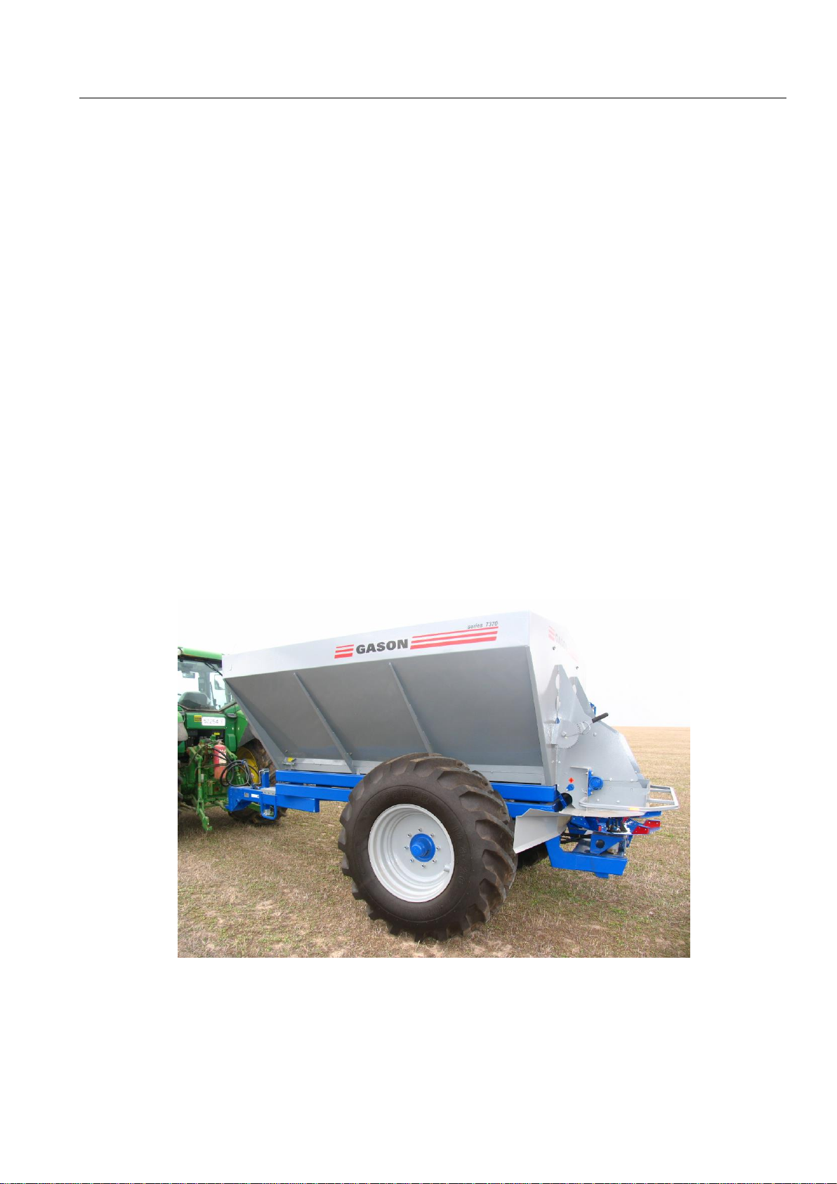
Fig. 1 7370 Series Fertiliser Spreader.
While every effort has been made to ensure the accuracy of the
information in this manual, AF Gason Pty Ltd reserves the right
to delete, change or add information without notice.

SAFETY
Page 2
09/08
The fertiliser spreader has been designed
with safety in mind. However, the equipment is
only as safe as the person operating it.
Do not operate the spreader until you
have read and understood this manual. If you
feel you need help or advice on the operation of
the Seeder, contact your local authorized
Gason Dealer.
To ensure trouble free and safe operation
of your spreader, it is important to carry out a
daily safety check to reduce the possibility of a
costly breakdown.
Items to Check Daily During
Operation
1. Check all wheel nuts are tight during the first
couple of days of use or after transportation
(refer page 6).
2. Check tyre pressures and tyre conditions in
general.
3. Ensure the safety guard around the spinners
is in place and is not damaged.
4. Check all hydraulic breakaway connections
are firmly engaged.
5. Check all hydraulic hoses and fittings for
leaks.
6. Check main spreader feed chain and drive
sprockets for wear or damage.
7. Check feed chain turns freely before
operating each day or after transporting
when loaded.
8. Check drawbar pin for wear.
9. Check main drive shear pins between the
gearbox and drive shaft are operational.
10. Check spinners for damage and wear before
operating and that they are clear of product if
starting near livestock or people.
General Safety Conditions
DO NOT ride on the machine when
operating.
DO NOT touch or attempt to adjust any
moving parts.
DO NOT adjust hydraulic fittings while under
pressure.
DO NOT remove any safety guards while the
spreader is operating.
DO carry out the daily safety checks and operate
the spreader in a safety conscious manner.
Hydraulics
Before working on the hydraulic system
always check that the spinners are not
operating, and that there is no pressure in the
hydraulic system.
Never attempt to disconnect a breakaway
coupling if the spinners are operating. Turn the
tractor off if working on the spinners or gearbox
lift cylinder of the spreader.
Leaving the Spreader Unattended
Ensure that the drop leg on the jack is
correctly pinned into position and that the foot is
on firm ground.
Chock the spreaders wheels to prevent it
from rolling if on a slope.
When Working on the Spreader
Place suitable stands under the trailer if
removing a wheel or carrying out major work.
Wear safety glasses if standing close to the
machine with the spinners operating.
Safety
Page 3
02/13
Transporting
Never transport the spreader with the
jockey wheel in contact with the ground wheel.
Use the transport lock on the rear of the
spreader to lock the gearbox in the transport
position.
Fig. G1 Transport lock for gearbox.
Before towing on the road you should
consult with the appropriate state or local
authority for any specific regulations and
permits that may be required e.g. dimension,
weight, time of day and bridge restrictions, area
category etc.
Do Not transport the spreader on public
roads when loaded. Do Not exceed 25km/h
when towing the spreader when loaded on
private roads. Maximum speed for towing an
empty spreader is 40km/h.
Always shift into low gear when travelling down
steep slopes. Always be aware that the braking
distance of the towing vehicle will be increased
when the Spreader is attached.
DO NOT TOW:
Without the gearbox transport lock engaged.
At speed over rough ground.
With any person or persons riding on the
machine.
At night unless lights are fitted and a permit
has been issued if required.
In a dangerous manner that may threaten the
safety of any person.
With the bin loaded on public roads.
Reverse the spreader with the gearbox jockey
wheel in contact with the tyre. Damage will
occur to the feed chain.
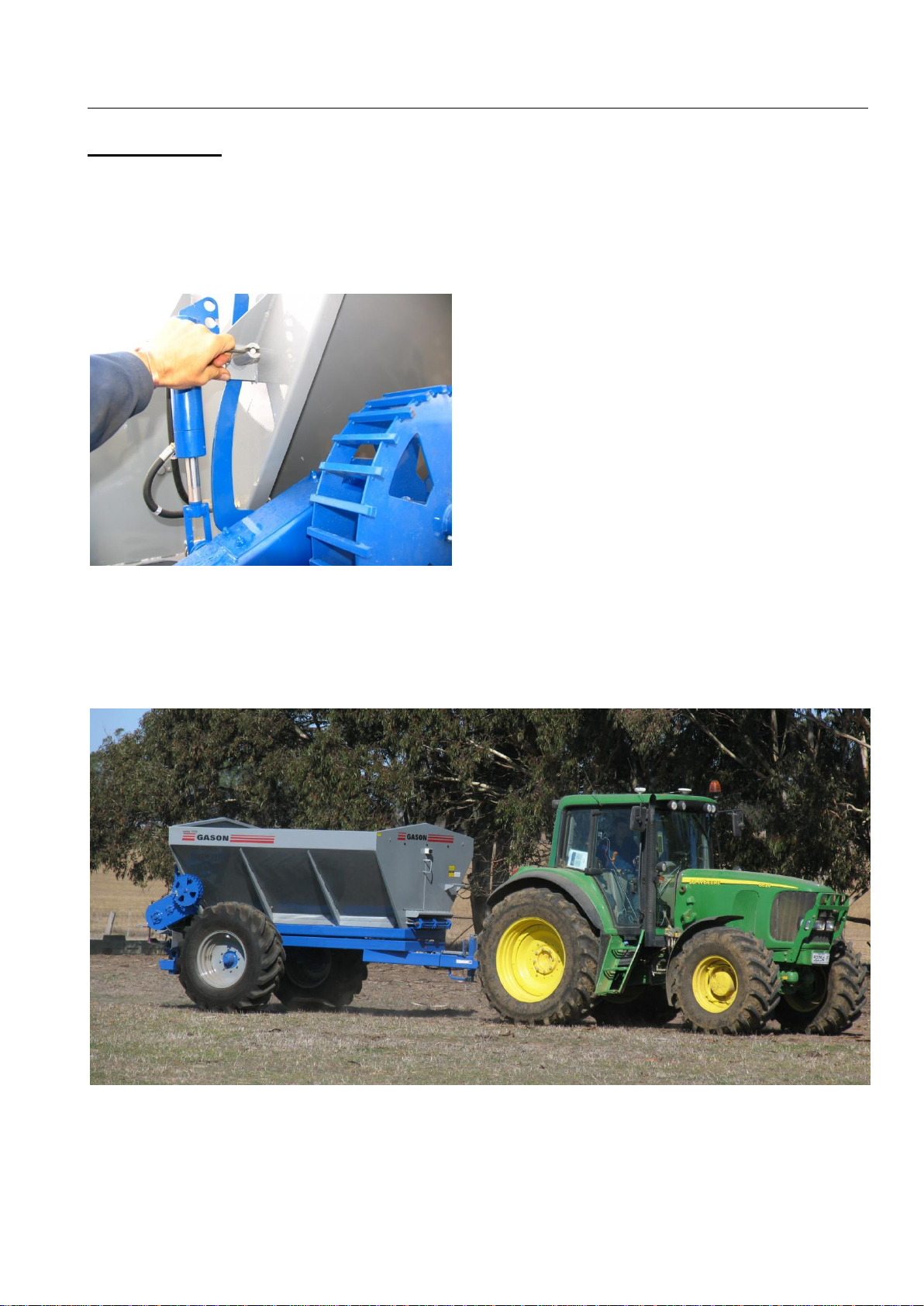
Fig. G2 7370 Spreader.

SPECIFICATIONS
Page 4
07/13
Dimensions
7350
7370
Overall width
2500
2500mm
Bin width
2355
2355mm
Overall height
2330
2330mm
Side of bin height
2185
2185mm
Overall length
4900
5500mm
Bin length
2400
3000mm
Wheel centres
2000
2000mm
Step height
565
565mm
Ground Clearance (rear)
460
460mm
Spinner height to ground
690
690mm
*Heights measured with 500mm under front hitch & no
hungry boards or tarp kit.
Spreader Weight
Unloaded
1530
1700kg
Max. Loaded Weight
(gross) @ 25 km/h
7130
8900kg
Bin Capacity
By volume:
Bin shape
4720
5900 Lt
By weight:
Urea (estimated)
3540
4425kg
Super (estimated)
5664
7080kg
(urea @ 750kg/1000 litres
(single super @ 1200kg/1000 litres)
Wheels
Size:
Rear tyres
18.4-26
18.4-26
Type:
Rear Tyres
R1 Gripster
Tyre
Recommended Pressure
kPa
psi
18.4-26 (12pr) Gripster
220
32
Hydraulics
Spinner Motor type . fixed displacement
........................ Gerotor Type
Connections............½” pressure inlet/main
return
Hydraulic capacity...56 I/min. @ 950rpm
(spinner)
Spinner Speed control….
........................pressure compensated
flow control valve.
Maximum motor
Pressure (cont.)......124 Bar (1800 psi)
Pressure (intermit.). 165 Bar (2400 psi)
Maximum return
line oil temp ............90° C max.
Hydraulic fluid.........Mobil fluid 424 or
equivalent High quality
High VI multigrade
transmission and
hydrostatic tractor oil.
Drive System
Gearbox......................3 speed
Type ..........................Chain & Sprocket
Sprockets....................Steel
Lubrication..................Mobil HP grease
............................(general purpose)

CONVERSION FORMULAE
Page 5
09/08
Useful Conversions –Formulae
LENGTH:
1 km = 0.621371 mile
1 mile = 1.609344 km
1 m = 3.280840 ft.
1 ft = 0.304800 m
1 mm = 0.039390 inch
1 inch = 25.400 mm
SPEED:
1km/h = 0.625 mph
AREA:
1 ha = 10,000 m2= 2.471054 acres
1 acre = 10 sq. chain = 4840 sq. yd. =
0.404685ha= 4840 sq.
yd. = 0.404685 ha
1 km2= 0.386102 sq. mile
1 sq. mile = 2.589988 km2
VOLUME:
1 m3 = 35.31476 cu. Ft.
1 cu. ft. = 0.028317 m3
1 L = 0.26418 US
gal.
1 US gal. = 3.78531 L
1 UK gal = 1.201 US
gal.
1 UK Bushel = 8.00 UK gal. = 1.2843 cu.
Ft. = 8.00 U.K. gal. = 1.2843 cu. ft.
= 1.2843 cu. ft.
1 L = 0.0274962 UK Bushels
1 UK Bushel = 36.369 L
1 L = 0.0283785 US Bushel
1 US Bushel = 35.2379 L
TORQUE:
1 Nm = 0.7375624 lbft.
1 lbft. = 1.3558175 Nm
FORCE:
1 lbf = 4.4482
N
1N = 0.22481 lbf
PRESSURE:
1 psi = 6.89476 kPa = 0.0689476 Bar
1 kPa = 0.145038 psi = 0.01 Bar
1 Bar = 14.5 psi
MASS:
1 kg = 2.204622 lb
1 lb = 0.453592 kg
1 kg = 1000
grams
POWER:
1 kW = 1.341
hp
1 hp = 745.7 W
DENSITY:
1 kg/m3 = 0.0624 lb/ft3
1 lb/ft3 = 16.0185 kg/m3
APPLICATION RATE:
1 kg/ha = 0.892 lb/acre
1 lb/acre = 1.121 kg/ha
HYDRAULIC HORSE POWER:
1 hp = FLOW (US GPM) x PRESSURE (psi)
1714

CONVERSION FORMULAE
Page 6
09/08
MASS FLOW RATE:
kg/min = Application Rate (kg/ha) x Area Rate (ha/hour)
60
lb/min = Application Rate (lb/acre) x Acre Rate (acre/hour)
60

BOLT SPECIFICATIONS
Page 7
06/07
STANDARD BOLT HEAD MARKINGS AND TORQUE SPECIFICATIONS:
CAUTION: Loose bolts can cause elongation of holes and part failures resulting in dangerous operating
conditions and equipment breakdown. Check all bolts and nuts periodically during equipment
operation and keep them tightened to the specified torque. If hardware replacement becomes
necessary, replace with equivalent metric grade number.
NOTE: The following torque figures are those recommended for zinc plated, lightly oiled bolts.
Recommended assembly torques may be obtained by multiplying the torque figures in the
table below by:
0.78 –for degreased zinc plated bolts
1.10 –for black oxide finished bolts
0.81 –for M20x2.5P Tine Toolbar Hardware
It is necessary that all bolts be tightened to the correct recommended assembly torque.
lbf.ft Nm lbf.ft Nm lbf.ft Nm
7/16 UNF 43 59 60 82 - -
7/16 UNC 39 53 54 74 - -
1/2 UNF 67 91 94 128 - -
1/2 UNC 59 81 83 113 - -
5/8 UNF 135 184 186 253 - -
5/8 UNC 117 159 165 224 - -
3/4 UNF 235 319 325 441 - -
3/4 UNC 210 285 290 394 - -
7/8 UNF 370 502 520 706 - -
7/8 UNC 335 455 470 638 - -
1UNF 550 746 775 1052 - -
1UNC 505 685 710 963 - -
M10 1.5 29 40 41 56 - -
M12 1.75 51 70 73 100 - -
M16 - - - - - 170 231
M16 2.0 126 171 180 245 - -
M18 - - - - - 243 330
M20 - - - - - 265 360
M20 2.5 247 335 351 477 - -
M22 - - - - - 340 462
M24 - - - - - 370 502
M24 3.0 425 577 608 825 - -
Recommended Assembly Torque
8.8
10.9
Wheel Stud
Metric Grade Number
S.A.E Grade Number
5
8
Size
Thread
Pitch
Wheel Stud
Head Markings
(Manufacturers marks
mayvary)
Head Markings
(Manufacturers marks
mayvary)

ORDERING PARTS
Page 8
06/07
When Ordering Parts:
The following information must be supplied to
facilitate fast and accurate processing of a
replacement parts order:-
•Gason part number and description (as
given in this manual)
•Quantity
•Machine model and serial number
•Method of despatch.
•Your Dealers name and address
For your convenience record the following
information below:
Name: ______________________________
____________________________________
Address: _____________________________
____________________________________
Telephone Number: ____________________
Machine Model No:_____________________
Date Machine Purchased:________________
Serial No.:____________________________
Subject to any applicable Federal, State or Territory laws or ordinances, which may apply from time to time, AF
Gason Pty Ltd reserves the right to make changes in design and specifications without notice or obligation and to
change or discontinue models at any time without incurring any liability to any Purchaser thereof.
Left and right hand: All references in this manual are determined by facing the direction of travel.
For warranty provisions please consult your Installation and Warranty Registration document.

ORDERING PARTS
Page 9
06/07
PART No.
DESCRIPTION
QTY.
COST
DATE

ASSEMBLY
Page 10
06/07
Introduction
The fertiliser spreader has been
assembled as far as practicable at the factory to
minimize the amount of work required in the
field. The unit has been inspected and tested
before it leaves the factory and requires only a
few basic checks before it is commissioned.
Lifting the Spreader
The Spreader has been supplied with 4
lifting points located at each corner at the top of
the bin. Use appropriate lifting chains or
shackles and slings. Ensure that the spreader is
empty before attempting to lift the spreader.
Spreader weight unloaded
7350 model 1530kg approx.
7370 model 1700kg approx.
Fig. G3 Tarp kit fitted to a 7350 model.
Final Pre-Delivery Check List
After the Spreader has been assembled
and the distribution system fitted to the
implement a final check should be carried out
before delivery.
Trailer General
1. All wheel nuts tight.
2. Safety hitch chain has been fitted.
3. Check tyre pressures.
4. Bins clean on inside, no loose items.
5. Spinner tacho is working.
Hydraulic Connections
The hydraulic system has been tested
prior to dispatch from the factory.
Standard 1/2'” breakaway connectors
have been fitted to the spreader hoses. When
connecting to the tractor, place the smaller
diameter hose inthe supply (pressure) remote
outlet on the tractor. The larger hose should
then be connected to the return flow remote.

OPERATION
Page 11
06/07
General Information
Before operating the spreader, check
that the machine is in good working order.
Tyres should be in good condition and
inflated to the correct pressure.
All feed chain bushes and bearings have
been greased.
Grease gearbox before using. Ensure
that the gear selector pin has been fully
pushed in before greasing the nipple at
the end of the pin.
Feed chain turns freely.
All 4 drive shaft shear pins are in place
and are the correct type.
Fig. G4 Drive shaft shear pins.
Adjustments Required for Different
Products
The spreader requires minimal
changes to spread a variety of products.
Feed Chain Cover Plate
Feed chain cover plates (qty 2), are
provided to protect the feed chain and
reduce chain loading when using free
flowing granulated fertiliser.
Fig. G5 Feed chain cover plates.
Centre Vee
The second item that may also need fitting or
removal is the centre vee at the rear of the
spreader that directs product towards the
centre of the spinners.
Fig. G6 Centre vee removed in discharge area.
Refer to Table G7 for suggested fitment
or removal of cover plates and centre vee.
Spinners
The standard spinners will do most work but
it may be necessary to use a low profile
H/Duty spinner when doing some types of
manures. If the manures are heavy and in
large clumps you may need to fit qty 2 x
H/Duty spinners (GPN 217162). Consult your
Gason dealer for more information.
Product Type
Example
Feed chain covers
Centre vee
Granulated
Urea, DAP,MAP, Super
In place
In place
Loose
Lime, Gypsum, Sand
Removed
Removed
Manures
Chicken litter, general manures
Removed
Removed
Table G7.

Operation
Page 12
06/07
Setting Spinner Speed
Spinner speed is one of the most
important factors in achieving an accurate
spread pattern. The spinner speed can be
adjusted from the cab on most modern
tractors if equipped with closed centre
hydraulics, or from the front of the spreader
by using the flow control valve on open
centre hydraulic equipped tractors.
Refer page 18 for a guideline of
suggested spinner speeds for various
products. Every product will spread
differently depending on its bulk density,
granule size, variation in size and shape.
An incorrectly set spinner speed can
influence the spread pattern. By adjusting
the spinner speed by as little as 50rpm up or
down, it is possible to improve or alter
spread pattern.
Fig. G8 Speed control from spreader. Normally
set to fully open position for closed centre
equipped tractors.
For this reason it is suggested that
a spread pattern test be carried out if
maximum accuracy is required.
As a guide, if the spinner speed is too
high there will be too much material directly
behind the spreader. If the spinner speed is
too slow there will be too little material
directly behind the spreader.
Maximum spinner speed for the 675mm
spinners is 1050rpm.
Fig. G9 Post June 2013 Tachometer at front of
spreader.
Engaging the Jockey Wheel
To operate the feed chain the jockey
wheel must be in contact with the ground
wheel. A hydraulic cylinder is used to raise
and lower the gearbox/jockey wheel. Before
operating the spreader in the field, check that
the transport lock has been pulled out and
rotated from the link arm.
Fig. G10 Transport lock for gearbox.
Once link is free to move, the gearbox /
jockey wheel can be lowered by engaging the
hydraulically driven spinners from the cab of
the tractor.
To disengage the feed chain lift the
gearbox / jockey wheel by reversing the flow
at the tractor’s controls. This will stop oil flow
to the spinners and raise the gearbox in one
operation.
Operation
Page 13
06/07
Use the transport lock if travelling
between paddocks or across roads.
Setting Application Rates
The application rate is controlled by:
1. The spread width of the product.
2. The bulk density of the product.
3. The gearbox ratio selected to run the
feed chain.
4. The rear door height setting.
Spreading Width
The maximum spread width, or bout
width for various products is determined by
a material’s bulk density, granule size and
granule shape. Some material will spread to
wide widths, such as granulated single
super, while lime and gypsum will only be
capable of spreading to a narrow width.
Refer to the table G26 on page 18 for
approximate spread widths for various
products.
Fig. G11 Bout width accuracy test.
To confirm the width for the actual
product being spread it will be necessary to
field-test the specific product and spreader
being used.
This process, if done correctly, involves
the collection of spread material in special
trays set out across the paddock at even
spacings.
The second and more simplistic method
to determine the approximate spread width is
to estimate the widthby eye. This can be done
by spreading a small amount of product at the
desired rate onto clear ground or onto alength
of shade cloth stretched out and pegged to the
ground that contrasts with the fertiliser. This
should demonstrate the approximate bout
width and the tapering off of product at the
extreme edges of the spread.
It may be necessary to drive over the
same path 2 or 3 times during the test if
spreading light rates of granular fertiliser.
The bout width is the distance that you
can drive apart on the paddock, maintaining
even coverage of product across the entire
paddock. The bout width will be less than the
overall spread width.
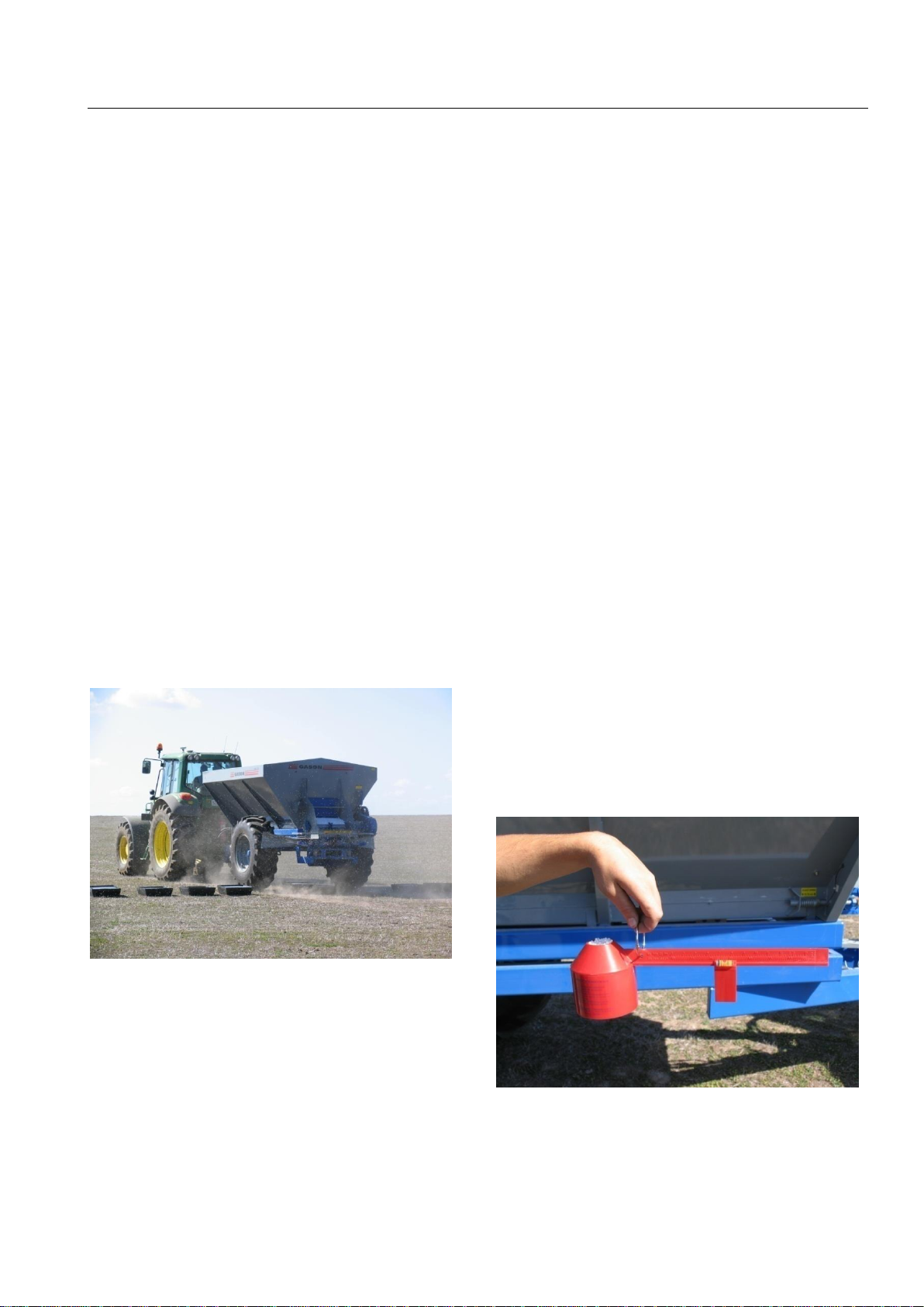
Determining Bulk Density
To determine the door and gearbox
setting it will help if you know the bulk density
of the particular product. This is done by using
the density meter that is supplied with the
spreader and by carrying out the following
steps.
Fig. G12 Density meter.
1. Fill the meter with product and level off.
2. Balance on ring and slide weight out until
level bubble is between the marks.
Operation
Page 14
06/07
3. Read density from the scale in tonnes per
cubic meter (top scale).
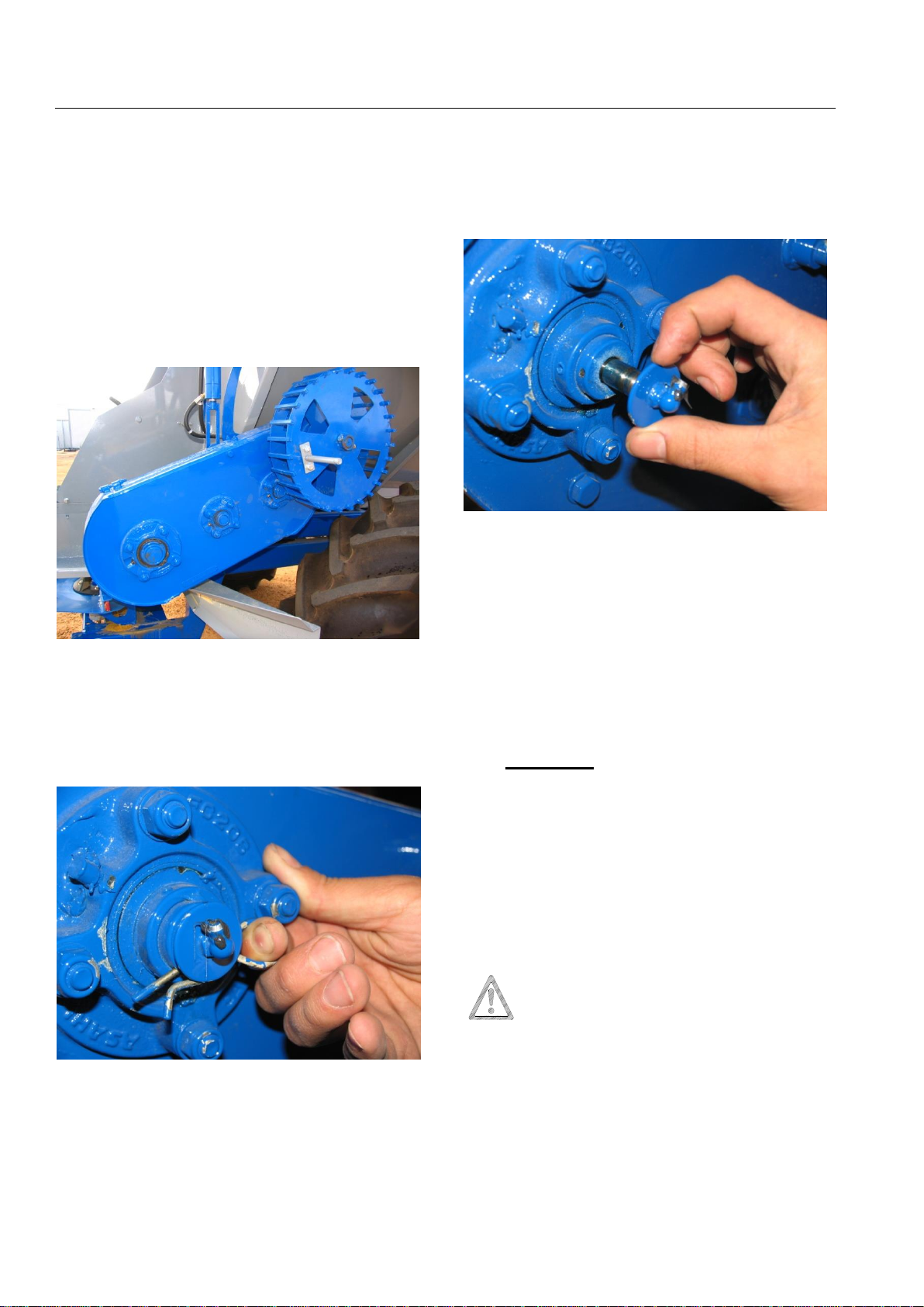
Changing Gearbox Ratio
The feed chain spreader is equipped
with a ground driven 3-speed gearbox. The
gearbox has been designed to offer a large
variation in feed chain speeds to cope with
the low and high application rates.
Fig. G13 Ground driven Gearbox.
To change between ratios you will
need to remove the clip from the inside face
of the top shaft (opposite the jockey wheel)
on the gearbox.
Fig. G14 Selector pin and clip.
Once removed, the selector pin can be
moved in to select low ratio, centralised to
select high ratio or fully withdrawn to drive
medium ratio. It will be necessary to either
rock the jockey wheel backwards and
forwards or to slowly turn the jockey wheel to
allow the internal drive key to slide from one
gear to the next.
Fig. G15 Selector pin central.
Once the correct ratio has been chosen
replace the retaining clip to lock the selector
pin into position.
Note: Always use the lowest gear
possible at the highest door setting to
minimise the loading on the gearbox.
Caution:
The rear door should never be
operated in the closed position with
fertiliser that can pack. On some fertilisers
it should not be operated with less than
40mm of gap as packing will occur and the
chain will jam.
IMPORTANT: Grease gearbox before
using. Ensure that the gear selector
pin has been fully pushed in before greasing
the nipple at the end of the pin.
Refer to the daily maintenance section on
page 20 for further information.

Operation
Page 15
06/07
Rear Door Adjustment
To set the rear door, remove the clip
from the adjusting handle and rotate to raise
or lower the door to the required position.
Fig. G16 Rear Door Adjustment.
A pointer, attached to the top of the
door, and calibration decal is used to show the
distance from the bottom of the floor to the
underside of the door. Replace the clip when
the door is set to the desired height.
Fig. G17 Rear Door Adjustment scale.
Fig. G18 Spreading urea.
APPLICATION RATE
Page 16
06/07
Setting Application Rate
Introduction
The application rate for the spreader
can be set as per the charts at the rear of the
manual or by calibrating the spreader.
The charts estimate the flow
characteristics of the product to determine
the door setting. Different products flow at
different rates. For instance, urea flows
faster than more irregular shaped products.
The chart can only estimate the actual door
setting required for the various application
rates.
If a high degree of accuracy is required,
particularly when spreading low rates, we
suggest a calibration test be performed. The
calibration process will allow the operator to
collect a sample of the actual product being
applied to determine the exact door setting
to achieve the desired application rate.
To collect a sample you will need to catch
the material as it falls off the feed chain. This
can be done by laying a small tarp or bag in
the rear discharge area of the spreader or by
purchasing a calibration kit (GPN 217025)
from your Gason Dealer. The kit includes 2
steel trays and a set of electronic scales to
allow you to collect a sample of product and
weigh it to determine your application rate.
Fig. G19 Optional Calibration kit
Application Rate by the Rate Chart
1. Determine the bulk density of the product.
2. Estimate the bout width that the spreader
will be driven.
3. Refer to the Rate Charts at the rear of the
manual to determine the rear door setting.
Note: Always use the lowest gear possible
at the highest door setting to minimise the
loading on the gearbox.
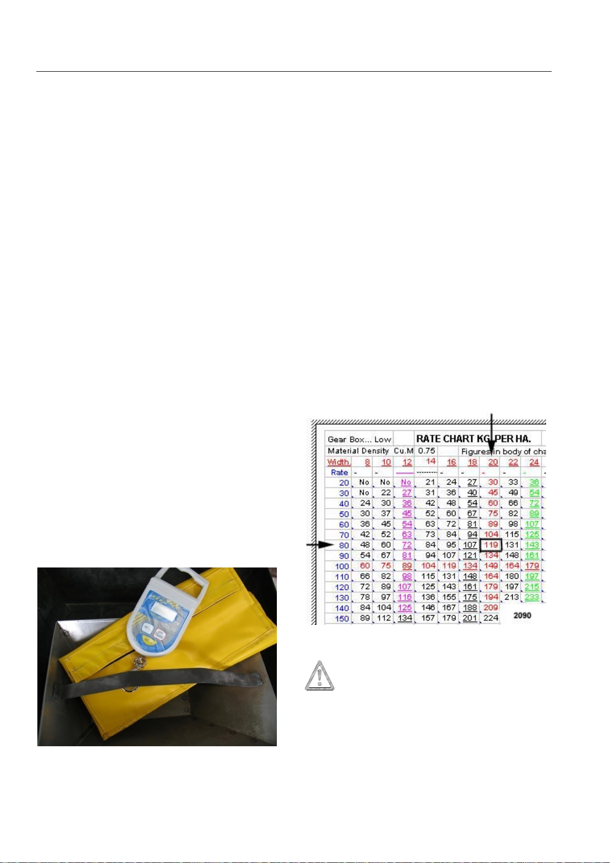
Example (Note. Examples in this section are
for demonstration only. Actual values may
differ from the charts in rear of book)
Shown in figure G20, urea that has a
bulk density of 0.75 tonnes per cubic metre is
to be spread to a 20 metre bout width at 80
kg/ha. By using the lowest gearbox ratio
possible, using the ‘Gear Box…Low’ chart,
and reading across the chart we can see that
the estimated rear door setting should be
119mm opening.
Fig. G20 Rate Chart example.
IMPORTANT: If the rate chart is the
only method to be used for setting the
rear door opening, a known weight of product
should be used in the spreader for the first
load to ensure the correct application rate is
being achieved.
This manual suits for next models
1
Table of contents
Other Gason Farm Equipment manuals


Popular Farm Equipment manuals by other brands

Schaffert
Schaffert Rebounder Mounting instructions

Stocks AG
Stocks AG Fan Jet Pro Plus 65 Original Operating Manual and parts list

Cumberland
Cumberland Integra Feed-Link Installation and operation manual

BROWN
BROWN BDHP-1250 Owner's/operator's manual

Molon
Molon BCS operating instructions

Vaderstad
Vaderstad Rapid Series instructions


