Gason VHD Delta Wing D15 User manual

VHD Delta Wing
The VHD Delta Wing Series
INFORMATION & PARTS MANUAL
Includes Side Throw & Rear Throw Models.
Covering the
D15 & D20 Models
GPN: 229011 Revision D
11/2023
COPYRIGHT
Neither this manual or part thereof may be reproduced or published
without the permission of AF Gason Pty Ltd
3349

Contents
Ordering Parts 3
Standard Bolt Head Markings And Torque Specicaons 4
Machine Specicaons 5
Machine Informaon & Troubleshoong 6
Assembly Instrucons 7
Grease Point Locaons 8
Parts Diagrams 9
General Assembly 10-11
Pull 12-13
Decals 14-15
Single Blade Set-up 16
Dual Blade Add On (Opon) 17
Blade Installaon - Rear Throw 18
Blade Installaon - Mulch Throw 19
Axle 20
Wing PTO Shas 21
Input PTO Sha (05/2021 - Current) 22
Input PTO Sha (Pre- 05/2021) 23
Transfer PTO Sha (D15) 24
Transfer PTO Sha (D20) 25
Gearbox - Cuerhead 26
Gearbox - Power Divider 27
Driveline - Rear Throw 28-29
Driveline - Mulch Throw 30-31
Driveline Guards 32
Guards - Rear Throw 33
Guards - Mulch Throw 34-35
Hydraulics - Wing Li 36
Hydraulics - Height Control 37
Oversize Sign & Tail Lights Kit (Opon) 38

The following informaon must be supplied to
your local dealer to facilitate fast and accurate
processing of a replacement parts order:-
• Gason Part Number (GPN) and
descripon (as given in this manual)
• Quanty Required
• Machine Model & Serial Number
For your convenience record the following
informaon below.
Dealer Name:
Dealer Address:
Dealer Phone Number:
Machine Model No:
Date of Purchase:
Serial Number:
Subject to any applicable Federal, State or Terri-
tory laws or ordinances, which may apply from
me to me, AF Gason Pty Ltd reserves the right
to make changes in design and specicaons
without noce or obligaon and to change or
disconnue models at any me without incurring
any liability to any Purchaser thereof.
Le and right hand: All references in this manual
are determined by facing the direcon of travel.
For warranty provisions please consult your In-
stallaon and Warranty Registraon document.
While every eort has been made to ensure the
accuracy of the informaon in this manual,
AF Gason Pty Ltd reserves the right to delete,
change or add informaon without noce.
Serial No. Tag At Right Front Of Machine
SERIAL No.
Ordering Parts
3
SERIAL No.
Serial No. Tag At Front Of Machine
3

As part of our service to the end consumer
Gason make every eort to ensure all bolts and
nuts are torqued using specic procedures during
the assembly process.
Throughout this parts manual the following sym-
bols may be seen which indicate important set-
ngs criccal to the connued safe operaon of
your mower/slasher.
Standard Bolt Head Markings And Torque Specicaons
4
: Always Replace after disassembly
: Critical Torque Setting (N m)
Where a Torque is not specied on a nut or bolt it
should be assumed that it is torqued according to
the following tables.
NOTE
The above gures are based on zinc plated, lightly oiled hardware.
Recommended assembly torques for alternave nish or applicaon, may be obtained by mulplying the torque gures in
the table by:
0.78 – for degreased zinc plated bolts.
1.10 – for black oxide nished bolts. 4

Machine Specicaons
55
OVERALL TRANSPORT WIDTH
OVERALL TRANSPORT HEIGHT
Dimensions*Machine Size
15 (4.6m) 20 (6m)
Minimum PTO HP190HP 120HP
Overall Length2(m) 4.8 6.32
Overall Transport Width (m) 2.5 2.5
Overall Transport Height (m) 2.49 3.09
Overall Weight (kg) 3740 4400
Cut Height (mm) 18-410 18-410
Drawbar Weight (tonne) 2.5 3.0
Blade Tip Speed (/min) 16745 21948
Jack 3 Tonne
Deck Material 6mm Deck, Fully Welded with 8mm side plates
Gearbox 210 HP power matched driveline
PTO Shas Comer T80 Series to boxes, Wide Angle VP9 input
Clutch Over run devise on input & 4 plate slip clutches on each V80 Sha
Skids 8mm Height Adjustable sides with 100 x 12mm spring steel base.
Rotor Bar 100 x 14mm spring steel
Blades 100 x 13mm swing back blades on hardened bushes.
Tyres Heavy duty otaon tyres 10/75-15.3 14 PLY
*all dimensions and masses are provided as a guide only if accurate dimensions are required it is recommended the specic machine be measured.
1 - Ensure Tractor Drawbar can supprot weight.
2 - Overall Length based on machine in transport posion. Machine length may vary when in operaon depending on cut height.
6
General
Gason Delta mowers are designed and built to with-
stand the toughest of condions from everyday
contractor demands to the seasonal roadside slash-
ing requirments, when cared for and maintained as
suggested in this and the general operators manu-
als.
Operang Speed
It is recommended that the Gason Delta mowers
be used at speeds of up to 8 - 15km/h Travelling at
speeds in excess of this may aect cut quality and
nish.
The speed will be dictated by the applicaon, ground
condions, tractor HP and cung height.
Gason recommend always commencing cung
at low operang speeds then steadily increasing
speed. The operator should always be observant of
the machine’s cung performance at all mes to
ensure a neat, even nish.
Cung Height
The Gason Delta Mower is designed to slash grasses
and general pasture and provide an even spread of
cut material. It is designed to cut at low heights. In
order to avoid premature wear or fague it is im-
peritave the machine be set-up correctly to avoid
ground contact when cung low.
Pull Angle
The Gason Delta Mower is designed to work through
a fore-a angle of ±15°from the horizontal. Working
the machine over ruts and bumps greater than this
may cause premature failure of the tow eye , pull or
PTO’s and may also damage blades and rotor bars.
6
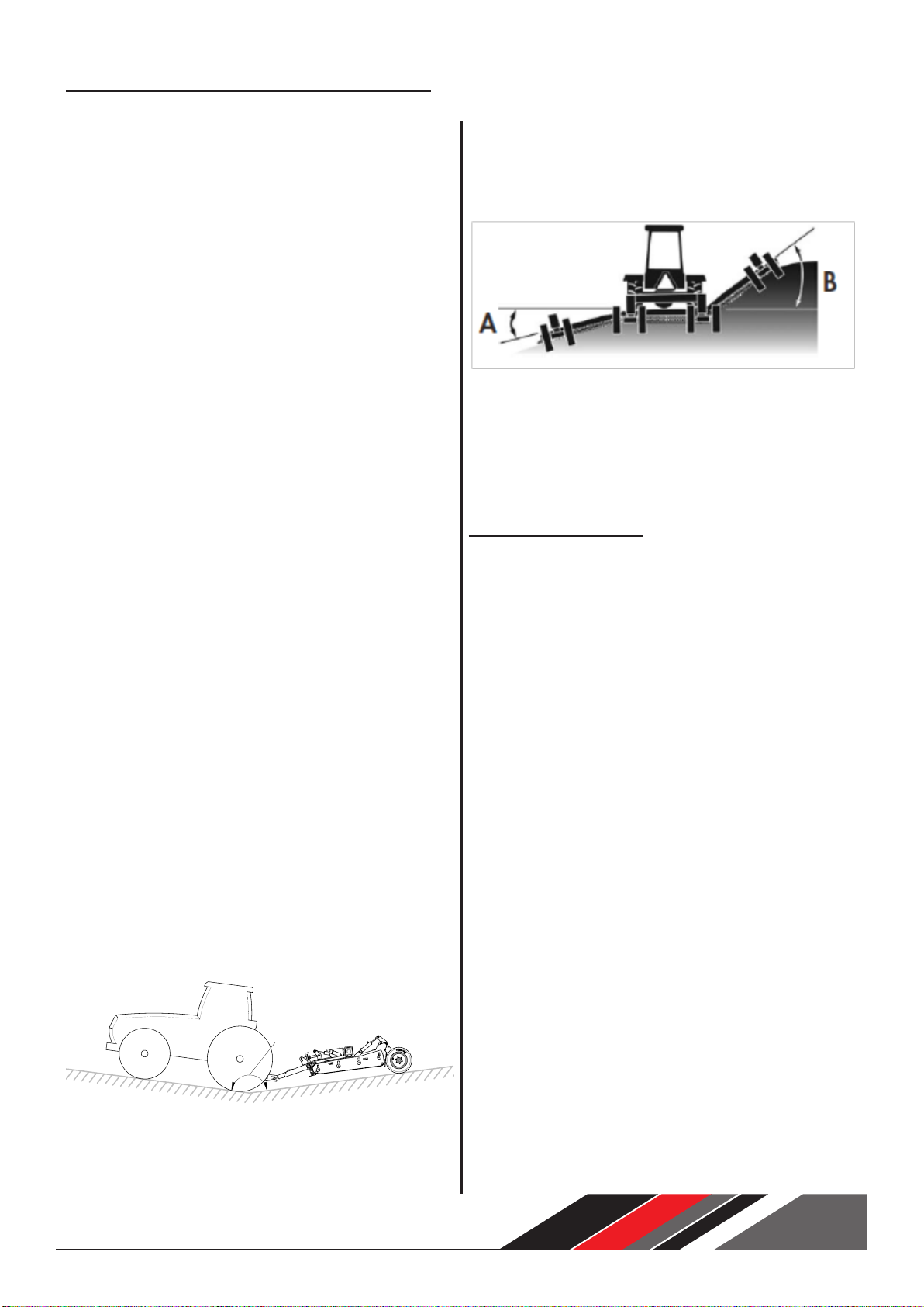
Machine Applicaon & Capabilies
165°
Wing Angle
The Delta Mower can operate in ground up to 45°
above and 20° below horizontal as represented in
the below image by leers A & B.
Gason recommend that at all mes the wheels re-
main in contact with the ground when in operaon.
Failure to do this may result in excess stress on cyl-
inders and may result in premature failure of the
machine.
Trouble Shoong
Why am I geng excessive skid wear?
In most cases excessive skid wear is a result of in-
correct machine set-up. Read the Tractor Connec-
on secon of the General Operators manual to aid
in nding the set-up error. As a guide, skid posion
should always be approximately 12mm from the
ground level when operang.
Why does my machine not follow the ground con-
tour?
The Delta Wing Mower uses an hyraulic oat sys-
tem. In order for this to work the tractor control
lever for the wing li circuit must be put into the
oat posion. Refer Tractor Operators manual for
more informaon on how to do this. Failure to do
this may result in premature wear of cylinder con-
necon points or in extreme cases cracking around
the hinges of the machine.
Why have my gearbox bolts come loose?
In most instances the bolts on the gearbox loosen
as a result of severe load being placed back into the
gearbox generally caused by connous scalping of
the ground.
Note: refer to torque specicaon page.

General
These assembly instrucons should be read in con-
juncon with the “General” Operators Manual sup-
plied. They are intended to provide model specic
details in addion to those in the General operators
Manual.
All Machine set-up should be conducted on at lev-
el ground to ensure even set-up across the machine.
Pull
The pull on the Gason Delta wing will generally be
shipped in a vercal posion and some assembly
will be required prior to conecng to the tractor.
The below image shows the posion the pull it likely
to be shipped in.
The Pull is a heavy components and will require the
use of a crane or forkli to be moved into posion.
Rotate pull to a horizontal posion and t hydraulic
cylinder and spring adjuster. Once complete t PTO
sha from idler sha to tee box. Prior to ng In-
put PTO read General Operators manual to ensure it
is cut to correct length to suit and is ghtened cor-
rectly.
Rear Crank
The rear crank on your Gason Delta Mower is likely
to be shipped in the posion shown above. Remove
all e downs and rotate crank again using a crane
or forkli to sit wheels on the ground, connect hy-
draulic cylinders to crank plate and posion wheels
to allow bolts to be put into crank plates to secure.
77
Assembly Instrucons

8
Grease Point Locaons
COMMON GREASE POINTS
6
2
1
3
4
57
ITEM
DESCRIPTION
NO OF POINTS
GREASE
INTERVAL
(hrs)
D15 D20
1
REAR CRANK ARMS
888
2
HINGES
448
3
PULL BOSS
228
4
PULL SWIVEL EYE
118
5
PULL TRANSFER LINK
118
6
PTO'S
VARIES WITH SHAFTS
8
7
WHEEL BEARINGS
6 6 100

Parts Diagrams
9
3342

3
14
12
6
4
5
1
213
10
8
7
16
9
15
17
17
17
17
17
GENERAL ASSEMBLY
3343
11
ITEM PART No.
DESCRIPTION
QTY.
SIZE
17 8001380
NIPPLE GREASE 1/8" NPT
15
-
16 926318
M8 x 50 COACH BOLT
20
15 926309
M8 x 30 COACH BOLT
26
14 917413
SCREW SET M10x45 GR8.8
4
-
13 913713
BOLT M20x65 GR8.8 HEX Z/P
4
-
12 909005
WASHER SPRING M10 x 2.35 x 2.40 Z/P
4
-
11 907301
WASHER FLAT 5/16x1"x1.2 ZP
46
-
10 903931
NUT NYLOC M20 CL8 AS1285
4
-
9 903302
NUT NYLOC M8
46
-
8 224979
WHEEL ASSY 10/75-15.3
6
-
7 223965
RUBBER FLAP - DELTA 20
2
6 223946
RH WING WELDMENT - DELTA 20
1
5 223946
LH WING WELDMENT - DELTA 20
1
4 223946
CTR DECK WELDMENT - DELTA 20
1
3 223408
PIN-WING PIVOT
4
A
2 223405
SKID - ANTI DROP
2
1 205892
BUSH DU- Ø50 x 50mm LONG
8
-
10
General Assembly

11
Item GPN Descripon Qty.
15’ 20’
1 205892 Bush Du- Ø50 x 50mm 8 8
2223405 Skid - An Drop 2 2
3223408 Pin-Wing Pivot 4 4
4223390 D15 - Centre Deck Weldment 1 -
223946 D20 - Centre Deck Weldment - 1
5 223390 D15 - LH Wing Assembly 1 -
223946 D20 - LH Wing Assembly - 1
6223390 D15 - RH Wing Assembly 1 -
223946 D20 - RH Wing Assembly - 1
7223963 D15 - Flap - Wing Rubber 2 -
223965 D20 - Flap - Wing Rubber - 2
8224979 Wheel Assy 10/75-15.3 6 6
9 903302 Nut Nyloc M8 46 46
10 903931 Nut Nyloc M20 4 4
11 907301 Washer Flat 5/16”x1”x1.2 ZP 46 46
12 909005 Washer Spring M10 ZP 4 4
13 913713 Bolt M20 x 65 GR8.8 Hex ZP 4 4
14 917413 Screw Set M10 x 45 4 4
15 926309 M8 x 30 Coach Bolt 26 26
16 926318 M8 x 50 Coach Bolt 20 20
17 8001380 Nipple Grease 1/8” NPT 15 15
223676 Chain 8mm 11 Links - Mower Ref. Ref.
General Assembly (Connued)

2117 10
4
3
19
14 15 18 20 7
8
1514
13
1
2316
2
11 2212
6
16 24
3345
5
9
PULL
ITEM PART No.
DESCRIPTION
QTY.
SIZE
24 917419
SCREW SET M10x16 GR8.8
2
-
23 917413
SCREW SET M10x45 GR8.8
1
-
22 917309 SCREW SET M8x 25x1.25P 3
-
21 916604
SCREW SET 1/2 UNC X 1 IN
4
-
20 912920
BOLT 1" x 6.5" UNC
1
-
19 912913
BOLT 1" x 9" UNC
2
-
18 912908
BOLT 1" x 6" UNC
1
-
17 908604
WASHER SPRING 1/2 x 5/32 x 5/32 ZP
4
-
16 907503
WASHER FLAT M12x24x1.6 ZP
3
-
15 906902
WASHER FLAT 1" x 2-1/8"x7G Z/P
4
-
14 903911
NUT NYLOC 1" UNC
4
-
13 903406
NUT NYLOC M10 CL8 AS1285
1
-
12 902302
NUT WHIZ FLANGE M8 x1.25P HEX ZP
3
-
11 224257
DOCUMENT HOLDER-BLACK
1
A
10 223952
BRACKET - GUARD MOUNT
1
A
9 223751
BOSS
1
A
8 223750
PIN DRAWBAR 1 1/4"DIA x 8-1/4"
1
7 223536
LINK ARM - SHORTENED
1
A
6 223530
CYLINDER MOD
1
A
5 223404
BRACKET - LINK
1
A
4 222671
HANDLE LOCKING
1
A
3 222669
WELDED 3T JACK ASSY
1
A
2 212530
BRACKET HYD.HOSE TIP
1
A
1 211089
HOSE STAND SPRING
1
A
12
Pull

13
Pull (Connued)
Item GPN Descripon Qty.
15’ 20’
1 211089 Hose Stand Spring 1 1
2 212530 Bracket Hyd. Hose Tip 1 1
3222669 Welded 3T Jack Assy 1 1
4 222671 Handle Locking 1 1
5223404 Bracket - Link 1 1
6223530 Cylinder Assy 3” x 8 1 1
7223536 Link Arm - Shortened 1 1
8 223750 Pin Drawbar 1 1/4” x 8-1/4” 1 1
9 223751 Boss 1 1
10 223632 Bracket - Guard Mount D15 1 -
223952 Bracket - Guard Mount D20 - 1
11 224257 Document Holder 1 1
12 902302 Nut Whiz Flange M8x1.26P Hex ZP 3 3
13 903406 Nut Nyloc M10 1 1
14 903911 Nut Nyloc 1” UNC Hex ZP 4 4
15 906902 Washer Flat 1” x 2-1/8” ZP 4 4
16 907503 Washer Flat M12x24x1.6ZP 3 3
17 908604 Washer Spring 1/2 x 5/32 x 5/32 ZP 4 4
18 912908 Bolt 1” X 6” UNC 1 1
19 912913 Bolt 1” x 9” UNC 2 2
20 912920 Bolt 1” X 6.5” UNC 1 1
21 916604 Screw Set 1/2” UNC x 1” 4 4
22 917309 Screw Set M8x25x1.25P 3 3
23 917413 Screw Set M10x45 GR8.8 1 1
24 917419 Screw Set M10x16 GR8.8 2 2

Decals
14
10
1 14
15
22
15
A
B
2
51513
3344
DETAIL A
21
24
3
23
8
18
7
124
16
9
19
20
16 20
17
6
DETAIL B
SCALE 1 : 16
20
16
11
DECALS
ITEM PART No.
DESCRIPTION
QTY.
SIZE
24 8001418
TAG SERIAL NO
1
A
23 8001251
SCREW DRIVE 1/2"x 6g-U ZP
4
-
22 804465
DECAL GASON-AN AUSTRALIAN
2
A
21 228234
DECAL-MOWER DANGER NOTICE
1
A
20 227410
DECAL - GEARBOX OIL
4
A
19 226754
DECAL - PTO SHAFT LENGTH
1
A
18 224328
DECAL-MOWER CAUTION STOP
1
A
17 224327
DECAL-MOWER PTO ROTATING
1
A
16 224323
DECAL-MOWER CAUTION GUARD
4
A
15 224322
DECAL-MOWER STAND CLEAR
5
A
14 224321
DECAL-MOWER WARNING DEBRI
2
A
13 224320
DECAL-MOWER WARNING BLADE
2
A
12 224318
DECAL-MOWER 1000RPM
1
A
11 224246
DECAL-MOWER DELTA 20 SM
2
A
10 224245
DECAL-MOWER DELTA 20 L
2
A
9 223523
DECAL TRANSPORT SPEED 20km/h
1
A
8 216072
DECAL-DO NOT RIDE
1
A
7 207998
DECAL TMA
1
-
6 207247
GASON LOGO DECAL
1
A
5 207246
DECAL GASON - A/S & MOWER
2
A
4 206995
DECAL - T/PORT WARNING
1
-
3 206955
DECAL WARNING -SAFETY
1
A
2 206694
TAPE WHITE REFLECTIVE - 60 x100mm
2
-
1 205830
TAPE RED REFLECTIVE - 60 x100mm
2
-

Item GPN Descripon QTY
15’ 20’
1 205830 Tape Red Reecve 2 2
2206694 Tape White Reecve 2 2
3206955 Decal - Warning Safety 1 1
4 206995 Decal - T/Port Warning 1 1
5237734 Decal - Gason 2 2
6 207247 Decal - Gason Logo 1 1
7 207998 Decal - TMA 1 1
8216072 Decal - Do Not Ride 1 1
9 223523 Decal - Transport Speed 20km/h 1 1
10 224243 Decal - Delta 15 Large 2 -
224245 Decal - Delta 20 Large - 2
11 224244 Decal - Delta 15 Small 2 -
224246 Decal - Delta 20 Large - 2
12 224318 Decal - 1000 RPM 1 1
13 224320 Decal - Warning Blade 2 2
14 224321 Decal - Warning Debris 2 2
15 224322 Decal - Stand Clear 5 5
16 224323 Decal - Cauon Guard 4 4
17 224327 Decal - PTO Rotang 1 1
18 224328 Decal - Cauon Stop 1 1
19 226754 Decal - PTO Sha Length 1 1
20 227410 Decal - Oil Fill Level 4 4
21 228234 Decal - Danger Noce 1 1
22 237737 Decal - Gason An Australian 2 2
23 8001251 Screw Drive 1/2”x6gU ZP 4 4
24 8001418 Tag - Serial Number 1 1
15
Decals (Connued)

16
: Critical Torque Setting (Nm)
: Always Replace after disassembly
508Nm
5
7
8
3
9
2
6
4
1
1
1
345Nm
NOTE:
FOR CLOCKWISE SET-UP ITEM
9
BECOMES GPN:223542
ALL OTHER PARTS REMAIN THE SAME
Single Blade Set-up
Item GPN Descripon Qty.
15’ 20’
1 903803 Nut Nyloc 3/4" UNF Gr8 Ref. Ref.
2223545 Bush - Blade 3/4" ID x 13mm Ref. Ref.
3 912818 Bolt 3/4" UNF x 2-3/4" Gr8 Ref. Ref.
4912853 Bolt 3/4" x 9" UNF Gr8 Ref. Ref.
5 228729 Spacer - Rotor Bar Block 1 1
6 223564 Clamp - Rotor 1 1
7223544 Rotor Bar - 725mm 2 -
230585 Rotor Bar - 1200mm - 2
8 223722 Rotor Bar Spacer - 725mm 1 -
230586 Rotor Bar Spacer - 1200mm - 1
9223543 Blade - 450mm ACW (Shown) 2 2
223542 Blade - 450mm CW Ref. Ref.
B
A
C
B - 345 Nm
C - 508Nm
ALL BOLTS TO BE LIGHTLY OILED.
ENSURE BLADES ROTATE FREELY AFTER TORQUING BOLTS.
Blade Bolt Kit - GPN: 225718
Includes:
223545: Bush - Blade 3/4”ID x 13mm
903803: Nut Nyloc 3/4” UNF Gr 8
912818: Bolt 3/4 UNF x 2-3/4” HT
345Nm
A - 345Nm

508Nm
: Critical Torque Setting (Nm)
: Always Replace after Disassembly
ALL BOLTS TO BE LIGHTLY OILED
ENSURE BLADES ROTATE FREELY AFTER TORQUING BOLTS.
Blade Bolt Kit - GPN: 225720
Includes:
230591: Bush - Blade 3/4”ID x 9mm
903803: Nut Nyloc 3/4” UNF Gr 8
912825: Bolt 3/4 UNF x 4” HT
6
4
3
1
2
5
3362
ITEM PART No.
DESCRIPTION
QTY
SIZE
6 912825
BOLT 3/4" x 4" UNF
4
-
5 903803
NUT NYLOC 3/4" UNF GR.8
4
-
4 230591
BUSH - BLADE 3/4"ID x 13mm
2
A
3 227408
SPACER 120 - DUAL MULCH BLADE
2
A
2 227407
ROTOR BAR CLAMP EXT.-173
2
A
1 224936
450mm FLAT BLADE
2
A
17
Dual Blade Kit (Opon)
GPN: 226254
Item GPN Descripon Qty.
1224936 450mm Flat Blade 2
2227407 Rotor Bar Clamp Ext. -173mm 2
3* 227248 Spacer 100 - Dual Mulch Blade 2
227408 Spacer 120 (pre - 12/2020) 2
4230591 Bush - Blade 3/4" ID x 13mm 2
5 903803 Nut Nyloc 3/4" UNF Gr8 4
6912825 Bolt 3/4" x 4" UNF Gr8 4
* Note: When ordering item 3, measure rotor bar
bar width and select correct spacer to suit.

18
2
2
1
C W
A C
AC
3358
ITEM PART No.
DESCRIPTION
QTY.
SIZE
2 236627
BLADE KIT AC- 20ft DELTA
2
A
1 236626
BLADE KIT CW - 20ft DELTA
1
A
Blade Installaon - Rear Throw
Item GPN Descripon QTY
15’ 20’
1236624 Blade Kit - Clockwise 1 -
2236626 Blade Kit - Clockwise - 1
3236625 Blade Kit - An Clockwise 2 -
4 236627 Blade Kit - An Clockwise - 2

19
A C
C W
CW
1
12
3352
ITEM PART No.
DESCRIPTION
QTY.
SIZE
2 236627
BLADE KIT AC- 20ft DELTA
1
A
1 236626
BLADE KIT CW - 20ft DELTA
2
A
Blade Installaon - Mulch Throw
Item GPN Descripon QTY
15’ 20’
1236624 Blade Kit - Clockwise 2 -
2236626 Blade Kit - Clockwise - 2
3236625 Blade Kit - An Clockwise 1 -
4 236627 Blade Kit - An Clockwise - 1

: Always Replace after disassembly
: Critical Torque Setting (Nm)
345Nm
14
11
412
1
97
6
15
13
3
10
582
3205
ITEM
PART No.
DESCRIPTION
QTY
15 922316
SCREW CAP M8x25
3
14 221039
AXLE STUB MACHINED
1
13 220749
HUB MACHINED
1
12 220748
STUD WHEEL M18x1.5
6
11 220747
SEAL RING
1
10 220746
WEAR RING
1
9220745
NUT SLOTTED M33x2
1
8220742
PIN SPLIT 8x80
1
7220741
NIPPLE GREASE 6mm
1
6220740
DUST CAP
1
5220739
BEARING OUTER 55x120x31.5
1
4220737
TRIPLE LIP SEAL
1
3220413
BEARING INNER 80x140x35.25
1
2217232
WASHER M8 RIB LOCK
3
1204622
WHEEL NUT M18 x 1.5 HEX
6
Axle
GPN: 220724
20
Item GPN Descripon Qty
1204622 Wheel Nut M18 X 1.5 Hex 6
2 217232 Washer M8 Rib Lock 3
3 205298 Bearing Inner 55x100x22.75 1
4220737 Triple Lip Seal 1
5 205297 Bearing Outer 40x80x19.75 1
6 220740 Dust Cap 1
7220741 Nipple Grease 6mm 1
8220742 Pin Split 8 x 80 1
9220745 Nut Sloed M33x2 1
10 220746 Wear Ring 1
11 220747 Seal Ring 1
12 204621 Stud Wheel M18x1.5 6
13 220749 Hub Machined 1
14 221039 Axle Stub Machined 1
15 922316 Screw Cap M8 x 25mm 3
16 204678 Axle Assembly Ref
This manual suits for next models
1
Table of contents
Other Gason Farm Equipment manuals


Popular Farm Equipment manuals by other brands

Schaffert
Schaffert Rebounder Mounting instructions

Stocks AG
Stocks AG Fan Jet Pro Plus 65 Original Operating Manual and parts list

Cumberland
Cumberland Integra Feed-Link Installation and operation manual

BROWN
BROWN BDHP-1250 Owner's/operator's manual

Molon
Molon BCS operating instructions

Vaderstad
Vaderstad Rapid Series instructions


