Gast 87R-10BA User manual

®
Registered Trademark/™ Trademark of Gast Manufacturing Inc. ©Copyright 2023 Gast Manufacturing Inc. All Rights Reserved.
www.gastmfg.com
ISO 9001 CERTIFIED
A UNIT OF IDEX CORPORATION
Part No. 6190762 (Rev B)
User Manual
87R-10BA
Beverage System

6190762 (Rev B) Beverage System User Guide
© 2023, Gast Manufacturing
We reserve the right to make any alterations which may be due to any technical improvements
Printed in the USA
Table of Contents
Table of Symbols ......................................3
System Features ......................................4
Operating Manual .....................................5
Maintenance ..........................................9
Schematics ..........................................10
Parts and Accessories ................................12
Technical Data and Specifications .....................13
Troubleshooting ......................................15
Warranty.............................................17
WARNING
PLEASE READ THIS MANUAL COMPLETELY BEFORE INSTALLING AND USING
THIS PRODUCT. SAVE THIS MANUAL FOR FUTURE REFERENCE AND
KEEP IN THE VICINITY OF THE PRODUCT.
IMPORTANT SAFETY INSTRUCTIONS AND REGULATORY INFORMATION
Congratulations on the purchase of your new GAST Compressor System. This system uses an oil-free rocking piston
air compressor that produces high-purity compressed air for use in beverage syrup dispensing or other pneumatic
applications.

Beverage System User Guide 6190762 (Rev B)
© 2023, Gast Manufacturing
We reserve the right to make any alterations which may be due to any technical improvements
Printed in the USA
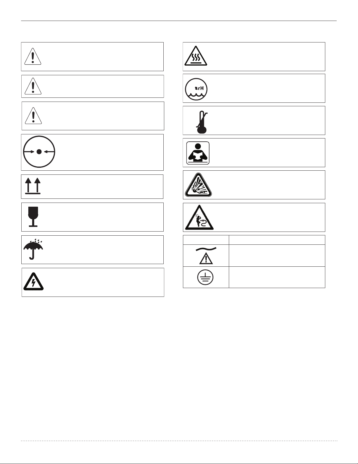
DANGER: Indicates an imminently hazardous
situation which will result in serious or fatal
injury if not avoided. This symbol is used only
in the most extreme conditions.
WARNING: Indicates a potentially hazardous
situation which could result in serious injury
if not avoided.
TABLE OF SYMBOLS
Electrical Shock Hazard.
Risk of electric shock present. Make sure power
is disconnected before attempting this procedure.
CAUTION: Indicates a potentially hazardous
situation which may result in minor or
moderate injury if not avoided. It may also be
used to alert against unsafe practices.
WARNING: To Avoid Serious Burns.
Do not touch surface during operation.
Indicates package should be handled with
these symbols pointing up.
FRAGILE: Handle package with care.
Indicates this package must be kept dry.
-29 °C
-20 °F
+50 °C
+122 °F
Indicates the acceptable shipping
temperature range.
95 Indicates the acceptable maximum
relative humidity for shipping.
372MM HG
.49 ATM
Indicates the acceptable lowest barometric
pressure conditions in which this unit
can be shipped.
Read operation and maintenance
manual before operating.
CAUTION: Risk of Bursting –
Do not adjust regulator to result in output
pressure greater than marked maximum
pressure of attachment.
WARNING: Risk of injury –
Do not direct air/nitrogen stream at body.
Symbol Description
A/C power
Ground

6190762 (Rev B) Beverage System User Guide
© 2023, Gast Manufacturing
We reserve the right to make any alterations which may be due to any technical improvements
Printed in the USA
System Features
REG & P. SWITCH ASM'S
DRYER/FILTER ASM'S
PUMP ASSEMBLY
TANK FEET
WALL MOUNT BRACKETS
TANK DRAIN
COOLING
COIL
K1054
FITTING KIT
3-PIECE
(PART 1/3)
K1054
FITTING KIT
COUPLING
(PART 3/3)
K1053
REGULATOR
ASSEMBLY KIT
K1052
PRESSURE SWITCH
ASSEMBLY KIT
DETAIL DRYER/FILTER ASM'S
SCALE 1 : 4
K1051
DRYER ASSEMBLY
K1051A
FILTER ASSEMBLY
DETAIL PUMP ASSEMBLY
SCALE 1 : 4
K1050
PUMP ASSEMBLY
NOTE: THERE IS ONLY ONE FITTING KIT, IT CONSISTS OF A
3-PIECE FITTING, A 2-PIECE FITTING AND A COUPLING.
THE 3-PIECE FITTING IS LOCATED BETWEEN THE PUMP
AND THE COOLING COIL. THE 2-PIECE FITTING IS LOCATED
BETWEEN THE PRESSURE SWITCH AND THE REGUATLOR.
THE COUPLING IS LOCATED ON THE TANK, UNDERSIDE OF
THE PUMP MOUNTING BRACKET.
K1054
FITTING KIT
3-PIECE
(PART 2/3)

Beverage System User Guide 6190762 (Rev B)
© 2023, Gast Manufacturing
We reserve the right to make any alterations which may be due to any technical improvements
Printed in the USA
Information
Please note that you can find the pictures and figures we are
referring to throughout the manual
Important - read this first!
Please read the following information and operating instructions
included with this product before use. This information is for your
safety and it is important that you follow these instructions. It will
also help prevent damage to the product. Failure to operate the
unit in accordance with the instructions or using unauthorized
spare parts can cause damage to the unit and could cause
serious injury.
CAUTION: To reduce risk of electric shock
• Only authorized service agents should carry out service.
Removing parts or attempting repairs can create an electric
shock. Refer all servicing to qualified service agents.
• If this unit is supplied with a three-pin plug, connect with a
properly earthed outlet only.
WARNING: To reduce risk of electrocution
• Do not use this unit with electrical voltages other than
stated on the rating plate located on the back of the system.
• Store in a dry place.
• Keep surrounding floor area dry around system.
• Do not reach for this product if it has fallen into liquid.
Unplug immediately.
• This unit is not weatherproof. Never operate outdoors in the
rain or in a wet area.
DANGER: To reduce risk of explosion or fire
• This unit is not intended to be used as a sprayer.
• Do not use this product in or near explosive atmospheres or
where aerosol products are being used.
• Do not allow compressor to intake any other gases other
than atmospheric air.
• Do not pump combustible liquids or vapours with this
product; do not use it in or near areas with combustible or
explosive liquids or vapours.
• Do not use this unit near open flames.
CAUTION: To prevent injury
• Compressed air/nitrogen can be dangerous; do not direct
airflow at a persons head or body.
• Always keep the system out of reach of children.
• Never operate this product if it has a damaged power lead
or plug, if it has been dropped or damaged, or if it has
fallen into water. Return the product to a service center for
examination and repair.
• Keep the electrical cable away from hot surfaces.
• Ensure all openings are kept free of restriction and never
place the system on a soft surface where the openings may
be blocked. Keep all openings free from dust, dirt and other
particles.
• Never insert fingers or any other objects into fans.
• This unit is thermally protected and can automatically
restart when the unit cools and the overload resets.
• Wear safety glasses, when servicing this product.
• Use only in well ventilated areas.
• This product may only be connected to units or tools with a
max. pressure rating higher or equal to that of the system.
• The internal surface of the system can get hot. Do not touch
internal system surface during operation. Keep the system
cover in place during operation.
• The surface of the system can get hot. Do not touch system
surface during operation.
Operating manual Failure to observe the safety precautions could result in severe
bodily injury, including death in extreme cases.
IMPORTANT: General directions for use
• Protect the system against rain, moisture, frost and dust.
• The system is constructed and approved for a max.
pressure as stated under Technical Specifications.
• Do not operate system at ambient temperatures exceeding
40°C/104°F or falling below 4°C/39°F.
• If the supply power lead on the system is defective, an
authorized distributor or other qualified personnel must
carry out the repair.
Warranty
Good Bad
Min. 4 °C/39 °F Max. 40 °C/104 °F
Provided that the operational instructions, maintenance, and
service have been carried out, your system is guaranteed against
faulty material or workmanship for 2 years. Reference warranty
statement at back of manual.
Conditions for Sale and Delivery will generally apply. Gast
Manufacturing, Inc. A/S reserves the right to change technical
specifications/constructions.
Contents of box
Your system should be delivered in a clean and undamaged box.
If not, contact your equipment provider immediately. The box
should contain the following:
• system
• system operating manual
• quick start guide
Unpacking
DO
• Ensure incoming line voltage is above Vac ( Vac for
high volt models)
• Ensure room temperature is below °C (°F)
• Inspect product for damage
• Ensure bottom and sides of system are clear from
obstruction
DON’T
• Throw away packaging, manuals, or part packet
• Install in a dusty/dirty non-ventilated or enclosed area
without proper cooling

6190762 (Rev B) Beverage System User Guide
© 2023, Gast Manufacturing
We reserve the right to make any alterations which may be due to any technical improvements
Printed in the USA
Installation
Your system is very easy to operate. Observe the following simple
instructions and you will get many years’ service from your unit.
• Visually inspect unit for shipping damage, contact your
supplier/shipper immediately if you think the unit may have
been damaged.
• Use only plumbing rated for °C [ °F] or higher. Ensure
that the plumbing has a sufficient internal diameter to avoid
pressure loss in the system (/ inch or larger). Check for
leaks.
A) Install product on a rigid level surface maintaining a
minimum of in/ cm clearance all around the unit and a
in/ cm clearance above the system.
• Sufficient cooling from the surroundings is important. Place
the system in a dustfree, dry and cool, yet frostfree, room. Do
not install in a closed cupboard, unless adequate openings
for ventilation are available (minimum cm²/ in²
each). If the system is placed under a table, a minimum of
in/. cm free height must be available above the system
or an opening of Ø cm/. inches, corresponding to the
top of the system, may be cut in the table. Ensure that the
system stands firmly on the floor.
WARNING: Install in a well ventilated area to provide
proper cooling. Unit must be shielded or placed in a
location so that it will be free from direct or indirect
contact with moisture or other contaminants, such as
water, food products, dust & dirt, etc.
Follow these steps to install your unit:
1. Securely connect output hose on the air supply line to the
/” hose barb on the regulator.
DO
• Securely fasten air line to system, pulling on it to to ensure it
is seated
• Check for leaks with soapy water
DON’T
• Allow kinks in the air line
2. Plug the system in.
DO
• Ensure the power switch is off on the compressor (O) before
connecting power
DON’T
• Plug in the system until all connections are made
• Cut or excessively bend the cord
• Use an extension cord smaller than recommended in gage
table on next page
3. Turn on the system and allow to fully pressurize, this could
take minutes depending on the installation.
DON’T
• Use the system during charging cycle
4. Run the system checks.
a. Verify pressure gauge on the front of the pressure switch
shows ~ psi ± psi
b. Verify the pressure gauge on the regulator
shows psi ± psi
c. Verify compressor does not operate for at least minutes
after installation and without using dispenser.
d. Verify air supply line and power cord are securely installed
e. Pour cups of beverage and ensure system cycles
Electrical Connection and Grounding Instruction
WARNING
Electrical Shock Hazard
This product must be properly grounded.
Do not modify the plug provided. If it will not fit the
outlet, have the proper outlet installed by a
qualified electrician.
If repair or replacement of the cord or plug is
necessary, do not connect the grounding wire to
either flat blade terminal. The wire with insulation
that is green or green with yellow stripes is the
grounding wire.
Check the condition of the power supply wiring.
Do not permanently connect this product to wiring
that is not in good condition or is inadequate for
the requirements of this product.
Failure to follow these instructions can result
in death, fire, or electrical shock.
Grounded Plug
Grounding Pin
Grounded Outlet
120-volt grounded connectors
shown. 220-/240-volt grounded
connectors will differ in shape.
Model with a power supply cord:
This product must be grounded. For 120-volt circuits, connect
power supply cord grounding plug to a matching grounded outlet.
Do not use an adapter. (See grounding plug diagram)
In the event of an electrical short circuit, grounding reduces the
risk of electric shock by providing an escape wire for the electric
current. This product may be equipped with a power supply cord
having a grounding wire with an appropriate grounding plug.
The plug must be plugged into an outlet that is properly installed
and grounded in accordance with all local codes and ordinances
Check with a qualified electrician or serviceman if the
grounding instructions are not completely understood, or if you
are not sure whether the product is properly grounded. Do not
modify the plug provided. If it will not fit the outlet, have the
proper outlet installed by a qualified electrician.

Beverage System User Guide 6190762 (Rev B)
© 2023, Gast Manufacturing
We reserve the right to make any alterations which may be due to any technical improvements
Printed in the USA
Extension Cords
Use only a 3-wire extension cord that has a 3-blade grounding
plug. Connect extension cord plug to a matching 3-slot
receptacle. Do not use an adapter. Make sure your extension cord
is in good condition. Check that the gage wire of the extension
cord is the correct size wire to carry the current this product will
draw.
An undersized cord is a potential fire hazard, and will cause a
drop in line voltage resulting in loss of power causing the product
to overheat. The following table indicates the correct size cord
for length required and the ampere rating listed on the product
nameplate. If in doubt, use the next heavier gage cord. The
smaller the gage number, the heavier the wire gage.
Minimum gage for extension cords
Amps Volts Length of cord in feet
120v 25 50 100 150 200 250 300 400 500
240v 50 100 200 300 400 500 600 800 1000
0-2 18 18 18 16 16 14 14 12 12
2-3 18 18 16 14 14 12 12 10 10
3-4 18 18 16 14 12 12 10 10 8
4-5 18 18 14 12 12 10 10 8 8
5-6 18 16 14 12 10 10 8 8 8
6-8 18 16 12 10 10 8 6 6 6
8-10 18 14 12 10 8 8 6 6 4
10-12 16 14 10 8 8 6 6 4 4
12-14 16 12 10 8 6 6 6 4 2
14-16 16 12 10 8 6 6 4 4 2
16-18 14 12 8 8 6 4 4 2 2
18-20 14 12 8 6 6 4 4 2 2
Electromagnetic Interference (EMI)
The system is designed to avoid electromagnetic emissions
interference with surrounding electrical equipment. Due to
the vast assortment of electrical equipment available, it is
possible that some interference may be experienced by the end
user. If interference is experienced, the device that is creating
interference should be removed from the room where the
generator is located. If the interference persists, then it may be
necessary to confirm that both devices are connected to isolated
circuits. If the problem still occurs, then the two devices should
be moved as far apart as possible. Finally, if the problem cannot
be eliminated, contact Gast Manufacturing.
Electrical Installation
WARNING
Incorrect electrical connection may result in electric
shock. The electrical connection must be carried out in
accordance with local electrical regulations and by qualified
personnel. Earthing of all AC models must be ensured during
installation. The capacitor must be earthed, as failure to do
so may cause electric shock when touched. Plug the system
into an earthed socket of nominal voltage and ensure that
fusing is adequate.
• For electrical connection, refer to schematic in back of this
manual.
• Check system serial number label for frequency and voltage
to ensure that it corresponds to the voltage and frequency
used for the system.
• Minimum of Amp rating on circuit breakers.
Operation
• If the temperature of the system is extremely low (for
instance after transportation or stocking), allow system to get
to room temperature before switching on the system.
• Do not use system for compression of liquids and dangerous
gases, such as petrol vapour and solvents.
• Do not lubricate the oil-less system with oil, as this will
destroy important components.
Indicates the ON and OFF position
for the equipment power switch
(system breaker)
When ON, voltage WILL be supplied
to the system.
When OFF, voltage WILL NOT be
supplied to the system.
I
o
= ON
= OFF
I
o

6190762 (Rev B) Beverage System User Guide
© 2023, Gast Manufacturing
We reserve the right to make any alterations which may be due to any technical improvements
Printed in the USA
Check the Pump Up Time
The pump up-time can be referenced to determine if the system
is experiencing any pneumatic leaks.
. Turn system off and un-plug. Remove the air connection to
the system’s outlet fitting.
. Completely drain the system of air by releasing air through
the outlet fitting (when hose is removed from fitting, press up
on the center stem of the fitting if system is equipped with a
quick disconnect fitting).
. Plug unit back in and turn system on.
. System will run for up to five minutes, then the pressure
switch will toggle the system off.
CAUTION
Always test the system when cold as the time indicated
refers to the pumping time of a cold compressor. The
pumping time of a warm compressor is much longer and
consequently, the result would be misleading.
Preventive maintenance
CAUTION
Loud Noise!
Test the safety valve:
• Once a year.
• Switch off system on the main switch and pull out the plug.
• Pull the ring at the end of the safety valve (see back of
manual).
Safety Valve
Monthly
Annually
Two years
5 years
10 years
Check compressor, air hoses and
equipment for leaks. Do this by
checking the pump up time •
Clean unit: wipe with soft,
damp cloth. If necessary, use
paraffin on rag to remove sticky
adhesions or dust/dirt that might
prevent cooling
•
Check intake filter on
compressor, replace if dirty •
Check inline filter element,
replace if dirty •
Check tank moisture •
Check O-rings in the non-return
valve and replace if damaged or
worn •
Test safety valve by gently pulling
the ring and releasing pressure
from the system. Clean if dirty •
Replace pressure switch and
membrane dryer •
Compressor rebuild (cups, seals,
valves) •
Conduct regulator’s preventative
maintenance •
Replace compressor, pressure
switch, and separator •
All kits are identified in the accessories portion of this manual.
WARNING
Electrical Shock Hazard
Disconnect electrical power supply cord before
performing maintenance on this product.
If product is hard wired into system, disconnect electrical
power at the circuit breaker or fuse box before
performing maintenance on this product.
Failure to follow these instructions can result in death,
fire, or electrical shock.
WARNING
Injury Hazard
Product surfaces become very hot during operation,
allow product surfaces to cool before handling.
Air stream from product may contain solid or liquid
material that can result in eye or skin damage, wear
proper eye protection.
Clean this product in a well ventilated area.
Failure to follow these instructions can result in burns,
eye injury, or other serious injury.
WARNING: Always disconnect power before
servicing. The head(s) surface(s) can be very hot
depending on compressor usage. Do not touch
these parts during or directly after operation.

Beverage System User Guide 6190762 (Rev B)
© 2023, Gast Manufacturing
We reserve the right to make any alterations which may be due to any technical improvements
Printed in the USA
WARNING
Disposal of system or components (once deemed non-usable
by the authorized dealer and end user) should be done in
accordance with all local codes. Contact your local waste
management authorities to determine proper disposal
methods.
WARNING
Do not exceed the OSHA requirements of 30 Psig/2 bar air
for cleaning purposes.
Replacing Non-Return Valve:
. Turn off system and unplug.
. Empty the system by bleeding with CPC.
. Remove the non-return valve from the system.
. Install new non-return valve.
Maintenance
By performing regularly scheduled maintenance, you will ensure
your system provides you with years of superior performance.
Also to extend your system life, please do the following:
• Keep system clean and free of dirt and debris.
• Keep area surrounding system clean and free of debris.
• Maintain recommended controlled ambient temperature –
high temperatures will shorten life.
• Verify all leaks are sealed
NOTE: Filter kits are available for the system
Replacing Inline Filters Element (see System Features):
. Turn off system and unplug.
. Disconnect compressor system from electrical power.
. Bleed air from system.
. Rotate filter bowl and drop down slightly to remove. Use
caution to not damage or kink the drain tubing or lose the
o-ring.
. Remove filter element by turning completely out and discard.
. Install a new . or micron filter element depending on
what filter is being serviced (verify correct part is installed).
Use caution to not damage the element stem.
. Position filter bowl by pushing up slightly and rotating into
place. Verify the drain tubing is not kinked or damaged, and
that the o-ring is on filter bowl.
. Reconnect electrical power to system.
Testing for Leaks:
. Disconnect air hose.
. Run system until it reaches maximum operating pressure
(approximately psi/. bar).
. Turn off the system.
. Let the system set for minutes.
. Verify the unit has not lost more than psi of pressure – this
would indicate a significant leak within the unit.
. Repair if needed, using soapy water to determine where leaks
are occurring.
. Connect air hose.
Replacing Intake Filter Element (see System Features):
. Turn off system.
. Disconnect system from electrical power.
. Remove intake filter cap by rotating it CCW.
. Remove old intake filter and discard.
. Install replacement filter and replace.
. Reconnect electrical power to system.

6190762 (Rev B) Beverage System User Guide
© 2023, Gast Manufacturing
We reserve the right to make any alterations which may be due to any technical improvements
Printed in the USA
Wiring Schematic
120 Vac – 60 Hz
L
OUT
IN
IN
OUT
INSULATE
: AUTO DRAIN
: FAN
: CAPACITOR
: EARTH
: TERMINAL CLIP
: MOTOR PROTECTION
: ADDITIONAL FEATURES
RED
BLUE (N)
BLACK
WHITE (L1)
INSULATE
YELLOW
BROWN
MOTOR 1
30 µF
CAPACITOR
30 µF
CAPACITOR
BLUE
GROUND (GREEN)
BROWN
WHITE (L1)
BLUE (N)
YELLOW
BROWN
COOLER
BOX
AUTOMATIC
DRAIN
PRESSURE
RELIEF
MOTOR 2
ORANGE
BROWN (L1)
BLUE (N)
YELLOW/GREEN
230 V/50-60 Hz
PRESSURE SWITCH
GREEN
GREEN
RED
BLACK ORANGE

Beverage System User Guide 6190762 (Rev B)
© 2023, Gast Manufacturing
We reserve the right to make any alterations which may be due to any technical improvements
Printed in the USA
Pneumatic Schematic
M
M
:INLET FILTER
:PRESSURE GAUGE
:PRESSURE SWITCH
:TANK
:WORKING PIPE
:STEERING PIPE
:COMPRESSOR
:SAFETY VALVE
:NON RETURN VALVE
:NON-RELIEVING REGULATOR
:PRESSURE RELIEF VALVE:
:MUFFLER
:FILTER WITH AUTOMATIC DRAIN
FILTER
.01μm
FILTER
5μm
:2-WAY NORMALLY OPEN VALVE
(PURGE & PRESSURE RELIEF)
COMPRESSED AIR OUTLET
REGULATED
PRESSURE
COMPRESSO
R
:COOLER
MEMBRANE DRYER
MANUAL DRAIN
:VALVE
TO CUSTOMER
PLUMBED DRAIN
MEMBRANE
DRYER

6190762 (Rev B) Beverage System User Guide
© 2023, Gast Manufacturing
We reserve the right to make any alterations which may be due to any technical improvements
Printed in the USA
Part no. Description
K1050 Service compressor kit
K1051 Dryer assembly kit - contains membrane dryer, filter kit (K1051A), respective fittings, &
mounting components
K1051A Filter assembly kit - contains 5 um, 0.01 um filter replacement kits, respective fittings &
mounting components
K1052 Pressure switch assembly kit - contains pressure switch, check valve, safety valve, power
cord, & all respective fittings.
K1053 Pressure regulator assembly kit - contains pressure regulator, pressure gauge, & respective
fittings
K1054 Fitting kit- contains all system fittings not contained in the above assembly kits
K1055 Annual preventative maintenance kit
AF631 Compressor shock mount
5418009A Manual tank drain
AF714 Tank foot
4390100 Cooling pipe
AP716 Capacitor
8008118 Wall mounting bracket
5416110 Safety valve - 11 BAR 160 PSI
5140000 Pressure gauge
Parts & Accessories List

Beverage System User Guide 6190762 (Rev B)
© 2023, Gast Manufacturing
We reserve the right to make any alterations which may be due to any technical improvements
Printed in the USA
Technical Data & Specifications
Specifications 87R-10BA
120 V
Frequency HZ 60
Flow @ 80 psi l/min 47
CFM 1.66
Max Current A 5.7
Weight kg 23
lbs 51
Pumping Time
(empty tank) seconds 85 seconds or less
Noise Level dB(A)/1m ≤65
Dimensions
(LxWxH)
mm 594 x 292 x 462
in 23.4 x 11.5 x 18.2
Motor HP 1/2
KW 0.37
Max Pressure bar 8.6
psi 125
Thermal Protection Yes
Pressure Dew Point 3°C or lower at a duty cycle of 50%, 0.57CFM
Relative Humidity % 20 - 80%*
Ambient Temperature 4°C to 40°C/39°F to 104°F
* Non-Condensing
The figures in the tables are based on the unit working in a clean environment at an ambient temperature of 20°C, relative
humidity of 50% and operating at sea level. The performance of the product will be adversely effected at high altitudes
(5000 feet and above).
Gast Manufacturing reserves the right to make technical modifications to these units as needed.

6190762 (Rev B) Beverage System User Guide
© 2023, Gast Manufacturing
We reserve the right to make any alterations which may be due to any technical improvements
Printed in the USA
Tank
Regulatory
Elec/Region Config
Accessory Configuration
Compressor Configuration
Air Accessory Type
Enclosure Style
Receiver Size
Family & Cylinders
86R - X X X - X X X X X
Family & cylinders Receiver Size Enclosure Style Air Accessory Type
86R = single cylinder & small bore (low
flow) O, 1.5, 3, 4, 15, 25, 40 B = Basic or Open Q = iQ dryer (2, 3, or 6 size)
87R = twin cylinder & large bore (high
flow) M = Metal Cabinet A = Membrane Dryer
LOA = single cylinder P = Plastic Cover N = Separator
(1=CMS, 2 Membrane)

Beverage System User Guide 6190762 (Rev B)
© 2023, Gast Manufacturing
We reserve the right to make any alterations which may be due to any technical improvements
Printed in the USA
Problem Possible Cause(s) Possible Solution(s)
1. System will not start
a. Power cord not connected to
system a. Verify that plug is connected to back of system and to wall
b. Store breaker tripped b. Unplug equipment on circuit to find fault. Reset circuit breaker.
Contact electrician or equipment provider if problem persists.
c. Voltage is to low c. Check voltage of system while unit is running and verify voltage is
above 110 V
d. Unit not turned on d. Turn unit on and verify operation
e. Plugged/clogged filters e. Remove filters and clean or replace as necessary. If problem
persists, contact equipment provider for replacement parts
f. Compressor not purging
pressure
f. Verify that unloader on pressure switch is venting compressor
head pressure by listening for purge noise (blast of air)
g. Ambient temperature is too high g. Check temperature. If above 104 °F [40 °C], adjust temperature or
relocate system to cooler location
2. Unit on - low
pressure
a. Plugged/clogged filters a. Remove filters and clean or replace as necessary. If problem
persists, contact equipment provider for replacement parts
b. Leaks in system b. Use soapy water to check for leaks in plumbing. Repair/replace as
needed
3. Unit noisy
a. Outlet plumbing is not securely
fastened to system or is
damaged
a. Manually check to make sure system plumbing is securely
fastened to system. Use soapy water to check for leaks in
plumbing. Repair/replace as needed
b. Safety relief valve is
continuously relieving
b. Pull relief valve ring. If problem persists contact equipment
provider
c. Membrane dryer is purging air c. Normal operation for the membrane dryer is to purge air through
the purge holes on the dryer
4. Unit runs
continuously
a. Leaks in system a. Use soapy water to check for leaks in plumbing. Repair/replace as
needed
b. Broken pressure switch b. Contact your equipment provider for replacement part
c. Membrane dryer purge rate out
of spec
c. An audible and increased flow can be felt from the 3 purge holes
on the membrane dryer. Contact your equipment provider for
replacement part
NOTE: Prior to all servicing unit should to turned off and unplugged from power source
Troubleshooting Guide

6190762 (Rev B) Beverage System User Guide
© 2023, Gast Manufacturing
We reserve the right to make any alterations which may be due to any technical improvements
Printed in the USA
Troubleshooting - continued
CAUTION
Switch off and isolate from electrical supply before removing
any parts from the system. Empty receiver of air before
dismantling parts of system. Only qualified personnel should
perform troubleshooting activities.
. System does not start:
a) No power from wall. Check circuit fuses and plug (no
fuses on system).
b) Breakage or loose connections in electrical wiring.
c) Defective capacitor.
d) The thermal protection has switched off the pump due
to overheating. When cooled the pump will automatically
turn on at a suitable operation temperature. Go through
the points in step .
e) The system has not been unloaded and there is back
pressure. Make sure that the system purges each time it
stops (listen for purge noise).
f) The pump is locked.
g) Pressure in the air receiver is too high for activation of the
pressure switch. The pressure switch completes circuit
only when pressure has dropped to preset start pressure.
Empty receiver. Relieve system pressure and restart.
. System does not start, makes a buzzing sound followed by a
clicking noise (cannot start against high pressure):
a) Leaky non-return valve. Use soapy water to find out
whether air leaks from the valve. If so, clean or replace.
System works, but pressure does not increase:
a) Intake filter clogged. Replace.
b) Leaks in fittings, tubes or pneumatic equipment. Check
with soapy water or by letting unit stay overnight with
disconnected mains. Pressure drop is not to exceed bar
(. psi).
c) Check the compressor cups. Replace, if necessary.
d) Defective valve plate. Contact your equipment provider.
e) Failure in non-return valve which is creating a flow
restriction.
. Loud noise from system:
a) Dirt or failure in non-return valve. Clean or replace.
b) System is purging during off cycle. This is normal
operation.
. System gets very hot:
a) Leaks. See Step b.
b) Too high ambient temperature. Ensure adequate
ventilation if the system is installed in a cabinet.
c) Overloaded. Allow system more cooling time between
operations.
. System starts when no air is being used:
a) Leaks. See Step b.
. System does not switch on against pressure or does not
switch off at max. pressure:
a) Defective pressure switch. Replace.

WARRANTY POLICY
Provided that the instructions for operation, maintenance and service have been carried out, your GAST compressor is guaranteed
against faulty material or workmanship for 2 years. The guarantee does not cover damage caused by violence, misuse, incorrect re-
pairs or use of unoriginal spare parts. Costs of transportation of parts/equipment are not covered by the guarantee. GAST’s Conditions
for Sale and Delivery will generally apply. GAST International A/S reserves the right to change technical specifications/constructions.
®
Registered Trademark/™ Trademark of Gast Manufacturing Inc. ©Copyright 2023 Gast Manufacturing Inc. All Rights Reserved.
www.gastmfg.com
ISO 9001 CERTIFIED
A UNIT OF IDEX CORPORATION
Gast Manufacturing
2300 M-139 Highway
Benton Harbor, MI 49023
Ph: 269-926-6171
Fax: 269-927-0808
www.gastmfg.com
Gast Group Limited
c/o IDEX Trading (Shanghai) Co., LTD
Room 3502-3505
No. 1027 Chang Ning Road,
Zhaofeng Plaza
Shanghai, China 200050
Phone +86-21-52415599
Fax +86-21-52418339
Table of contents