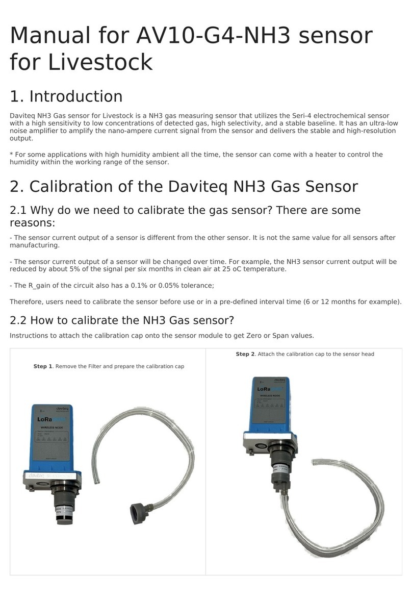
GasTech D-GUARD2R User manual

D-Guard²R Instruction Manual
Item Number 2010252Rev 1: 2023-07-28
1 Introduction
The D-GuardR is a single gas fixed detector with a large range of available sensors and an easy to
use interface. The D-GuardR features alarm relays
Figure 1.D-GuardR.
2 Method of Operation
The D-GuardR detects toxic or flammable gas and can interface with external equipment to trigger
alarms or operate additional equipment. The D-GuardR can be fitted with an oxygen sensor to
measure the oxygen concentration in the environment.
The D-GuardR detects gas via diusion to the sensor at normal atmospheric pressure.
3 For Your Safety
4 Further Information
Please tell us if you want help with this equipment.
Head Oce: Gastech, 24 Baretta Road, Wangara, WA 6065, Australia.
Warning: Do not make changes to this D-Guard²R without the express written permission of
Gastech Australia Pty Ltd. Changes that are not approved can cause death or injury
to personnel.

D-Guard²R Instruction Manual
Item Number 2010253Rev 1: 2023-07-28
Table of Contents
Introduction . . . . . . . . . . . . . . . . . . . . . . . . . . .
Method of Operation . . . . . . . . . . . . . . . . . . . . . . . .
For Your Safety . . . . . . . . . . . . . . . . . . . . . . . . . .
Further Information . . . . . . . . . . . . . . . . . . . . . . . . .
List of Figures . . . . . . . . . . . . . . . . . . . . . . . . . . .
Keywords and Symbols Used in This Manual . . . . . . . . . . . . . . . .
Intended use . . . . . . . . . . . . . . . . . . . . . . . . . . .
Safety Precautions . . . . . . . . . . . . . . . . . . . . . . . . .
Models covered by this instruction manual . . . . . . . . . . . . . . . . .
What is in the Box?. . . . . . . . . . . . . . . . . . . . . . . . .
Installation Information . . . . . . . . . . . . . . . . . . . . . . .
.D-GuardR Mechanical Installation . . . . . . . . . . . . . . . . . .
Electrical Installation . . . . . . . . . . . . . . . . . . . . . . . .
Response Test . . . . . . . . . . . . . . . . . . . . . . . . . .
Operation . . . . . . . . . . . . . . . . . . . . . . . . . . . .
.Power up . . . . . . . . . . . . . . . . . . . . . . . . . .
.Home screen features . . . . . . . . . . . . . . . . . . . . . .
.Unlock the menu screen . . . . . . . . . . . . . . . . . . . . .
.Passcode Requested . . . . . . . . . . . . . . . . . . . . . .
Calibration . . . . . . . . . . . . . . . . . . . . . . . . . . .
.Go to the calibration menu . . . . . . . . . . . . . . . . . . . .
.Attach the calibration gas to the D-GuardR. . . . . . . . . . . . . . .
.Calibration Modes . . . . . . . . . . . . . . . . . . . . . . .
.Calibration Trend Bar . . . . . . . . . . . . . . . . . . . . . .
.Auto Zero Calibration. . . . . . . . . . . . . . . . . . . . . . .
.Auto Span Calibration . . . . . . . . . . . . . . . . . . . . . .
.Manual Zero Calibration . . . . . . . . . . . . . . . . . . . . .
.Manual Span Calibration . . . . . . . . . . . . . . . . . . . . .
System Information . . . . . . . . . . . . . . . . . . . . . . . .
Status . . . . . . . . . . . . . . . . . . . . . . . . . . . . .
.Clear Latched Alarms . . . . . . . . . . . . . . . . . . . . . .
Sensor Settings . . . . . . . . . . . . . . . . . . . . . . . . . .
.Go to the Sensor Settings Menu. . . . . . . . . . . . . . . . . . .
.Set Detector Full Scale . . . . . . . . . . . . . . . . . . . . . .
.Set Span Gas Concentration . . . . . . . . . . . . . . . . . . . .
.Set Zero Gas Concentration . . . . . . . . . . . . . . . . . . . .
.Set Suppression Band . . . . . . . . . . . . . . . . . . . . . .
.Sensor Gain . . . . . . . . . . . . . . . . . . . . . . . . .
Alarm Settings . . . . . . . . . . . . . . . . . . . . . . . . . .
.Go to the Alarm Settings menu . . . . . . . . . . . . . . . . . . .
.Alarm Direction . . . . . . . . . . . . . . . . . . . . . . . .
.Alarm Level . . . . . . . . . . . . . . . . . . . . . . . . .
.Alarm Relay state. . . . . . . . . . . . . . . . . . . . . . . .
.Alarm Latch . . . . . . . . . . . . . . . . . . . . . . . . .
.Latched Alarm Examples . . . . . . . . . . . . . . . . . . . . .

D-Guard²R Instruction Manual
Item Number 2010254Rev 1: 2023-07-28
System Settings. . . . . . . . . . . . . . . . . . . . . . . . . .
.Access the System Settings . . . . . . . . . . . . . . . . . . . .
.Isolate . . . . . . . . . . . . . . . . . . . . . . . . . . .
.Set Passcode . . . . . . . . . . . . . . . . . . . . . . . . .
.Disable Passcode . . . . . . . . . . . . . . . . . . . . . . .
Advanced Settings . . . . . . . . . . . . . . . . . . . . . . . . .
.Go to the Advanced Settings Menu . . . . . . . . . . . . . . . . .
.System Calibration . . . . . . . . . . . . . . . . . . . . . . .
.-mA Output Test. . . . . . . . . . . . . . . . . . . . . . .
.Relay Function Test . . . . . . . . . . . . . . . . . . . . . . .
.Reset Sensor Life. . . . . . . . . . . . . . . . . . . . . . . .
.Sensor Presets . . . . . . . . . . . . . . . . . . . . . . . .
Error Codes . . . . . . . . . . . . . . . . . . . . . . . . . . .
-mA Output Fault Conditions . . . . . . . . . . . . . . . . . . . .
Specifications . . . . . . . . . . . . . . . . . . . . . . . . . .
.Enclosure Specifications . . . . . . . . . . . . . . . . . . . . .
.Mechanical Specifications. . . . . . . . . . . . . . . . . . . . .
.Environmental Specifications. . . . . . . . . . . . . . . . . . . .
.General Specifications . . . . . . . . . . . . . . . . . . . . . .
.Wiring Specifications . . . . . . . . . . . . . . . . . . . . . .
.D-GuardR Versions, Gas, Range, and Resolution . . . . . . . . . . . . .
Warranty . . . . . . . . . . . . . . . . . . . . . . . . . . . .
.Sensor Warranty periods . . . . . . . . . . . . . . . . . . . . .
Replacement Parts . . . . . . . . . . . . . . . . . . . . . . . . .
.Replacement Parts - exploded view . . . . . . . . . . . . . . . . .
.Replacement parts - list . . . . . . . . . . . . . . . . . . . . .
PCB (Part number -) Configuration Jumpers . . . . . . . . . . . . .
Maintenance . . . . . . . . . . . . . . . . . . . . . . . . . . .
.Calibration Interval . . . . . . . . . . . . . . . . . . . . . . .
.Cleaning . . . . . . . . . . . . . . . . . . . . . . . . . .
.Visual Inspection . . . . . . . . . . . . . . . . . . . . . . . .
Gastech Policy Statements . . . . . . . . . . . . . . . . . . . . . .

D-Guard²R Instruction Manual
Item Number 2010255Rev 1: 2023-07-28
5 List of Figures
Figure .D-GuardR. . . . . . . . . . . . . . . . . . . . . . . . . .
Figure .Keywords and symbols used in this manual. . . . . . . . . . . . . . .
Figure .List of supplied items.. . . . . . . . . . . . . . . . . . . . . .
Figure .D-GuardR mounting dimensions in millimetres. . . . . . . . . . . . . .
Figure .Arrows show magnetic sensor positions. . . . . . . . . . . . . . . .
Figure .D-GuardR menu icons. . . . . . . . . . . . . . . . . . . . . .
Figure .D-GuardR splash screen. . . . . . . . . . . . . . . . . . . . .
Figure .D-GuardR at sensor warm up.. . . . . . . . . . . . . . . . . . .
Figure .D-GuardR normal operating screen. . . . . . . . . . . . . . . . .
Figure .Main display layout. . . . . . . . . . . . . . . . . . . . . . .
Figure .Menu locked. . . . . . . . . . . . . . . . . . . . . . . . .
Figure .Menu unlocked. . . . . . . . . . . . . . . . . . . . . . . .
Figure .Trend Bar states. . . . . . . . . . . . . . . . . . . . . . . .
Figure .Sensor Gain Warning. . . . . . . . . . . . . . . . . . . . . .
Figure .Span Gas Concentration Warning. . . . . . . . . . . . . . . . . .
Figure .Zero Gas Concentration Warning. . . . . . . . . . . . . . . . . .
Figure .Sensor gain warning. . . . . . . . . . . . . . . . . . . . . .
Figure .Minimum alarm level warning. . . . . . . . . . . . . . . . . . .
Figure .Maximum alarm level warning. . . . . . . . . . . . . . . . . . .
Figure .AL and AL Latched. . . . . . . . . . . . . . . . . . . . . .
Figure .AL Latched. . . . . . . . . . . . . . . . . . . . . . . . .
Figure .AL Latched. . . . . . . . . . . . . . . . . . . . . . . . .
Figure .D-GuardR home screen when isolated. . . . . . . . . . . . . . . .
Figure .Error codes. . . . . . . . . . . . . . . . . . . . . . . . .
Figure .- mA output loop fault currents. . . . . . . . . . . . . . . . .
Figure .D-GuardR dimensions in millimetres (front view). . . . . . . . . . . . .
Figure .D-GuardR dimensions in millimetres (side view). . . . . . . . . . . . .
Figure .D-GuardR Mechanical specifications.. . . . . . . . . . . . . . . .
Figure .D-GuardR Environmental specifications.. . . . . . . . . . . . . . .
Figure .D-GuardR Specifications. . . . . . . . . . . . . . . . . . . . .
Figure .D-GuardR Electrical connections. . . . . . . . . . . . . . . . . .
Figure .D-GuardR versions.. . . . . . . . . . . . . . . . . . . . . .
Figure .Sensor warranty periods in months. . . . . . . . . . . . . . . . .
Figure .D-GuardR replacement parts - exploded view.. . . . . . . . . . . . .
Figure .D-GuardR replacement parts list. . . . . . . . . . . . . . . . . .
Figure .PCB - jumper locations. . . . . . . . . . . . . . . . . . .
Figure .PCB - jumper settings. . . . . . . . . . . . . . . . . . .
Figure .Splash Guard. . . . . . . . . . . . . . . . . . . . . . . . .

D-Guard²R Instruction Manual
Item Number 2010256Rev 1: 2023-07-28
6 Keywords and Symbols Used in This Manual
Symbol Keyword Description
No
Symbol Warning Warning: Do not (warning text). Can cause injury or death to
personnel.
No
Symbol Caution Caution: Do not (caution text). Can cause damage to parts or
equipment.
Service tool Combined magnetic wand and hex key service tool
Calibration plug Calibration adapter
No
Symbol Full Scale The user selectable range of the detector. This cannot exceed
the maximum range of the sensor.
No
Symbol Suppression Band The suppression band prevents the D-GuardR from displaying
small changes in the detected gas level close to zero.
No
Symbol Sensor Gain The sensor gain adjusts the amplification of the sensor output.
No
Symbol AL1 User configurable Alarm 1
No
Symbol AL2 User configurable Alarm 2
No
Symbol IP Ingress Protection Rating
Figure 2.Keywords and symbols used in this manual.

D-Guard²R Instruction Manual
Item Number 2010257Rev 1: 2023-07-28
7 Intended use
The D-GuardR is designed as a fixed gas detector with a 4-20 mA current loop output. The
detector can interface with external equipment to transmit gas levels and trigger external alarm
devices.
8 Safety Precautions
9 Models covered by this instruction manual
Please refer to the D-GuardR Versions for a list of all models covered by this manual.
Warning: The D-Guard²R detects toxic and flammable gases and oxygen concentrations.
These gases can cause injury or death to personnel.
Warning: The D-Guard²R is not a personal gas detector. If you do not use a personal gas
detector this can cause injury or death to personnel.
Warning: Do not use the D-Guard²R in an explosive or oxygen rich atmosphere. An explosion
can cause injury or death to personnel.
Warning: You must do a response test before first use. Incorrect calibration can result in injury
or death to personnel.
Caution: This manual is intended for the non-certified general version of the D-Guard²R. Do
not use this manual for other models in our range.
Warning: You must obey all caution and warning statements in this instruction manual. Failure
to obey can result in injury or death to personnel.

D-Guard²R Instruction Manual
Item Number 2010258Rev 1: 2023-07-28
10 What is in the Box?
Item Description
D-GuardR gas detector
D-GuardR Service Tool. The service tool activates the internal menu
magnetic sensors and includes an integrated 4mm hex key to open the
enclosure.
The Quick Start Guide (QSG) provides a brief overview of the installation
and operation of the D-GuardR gas detector.
Calibration Certificate. The D-GuardR is factory calibrated before dispatch.
Calibration plug
Figure 3.List of supplied items.

D-Guard²R Instruction Manual
Item Number 2010259Rev 1: 2023-07-28
11 Installation Information
11.1D-GuardR Mechanical Installation
The D-GuardR should be mounted vertically to a suitable flat surface. Make sure the cable gland
faces the ground. Use the two mounting eyes with M6 fasteners suitable for the surface type. Make
sure the data plate, on the right hand side, remains visible after installation.
Figure 4.D-GuardR mounting dimensions in millimetres.
Splash Guard
Warning: The D-Guard²R must be installed by an approved person. Incorrect installation can
cause injury or death to personnel.
Caution: Do not over tighten the M6 fasteners as this can cause distortion of the enclosure.
Caution: Water or dust on the Splash Guard can interfere with gas detection.

D-Guard²R Instruction Manual
Item Number 20102510 Rev 1: 2023-07-28
12 Electrical Installation
Socket Head
Cap Screws
Socket Head
Cap Screws
Warning: The D-Guard²R must be installed by an approved person. Incorrect installation can
cause injury or death to personnel.
Step 1. Loosen the 4 screws holding the top case on.
Step 2. Open the D-GuardR enclosure.
Step 3. Connect the D-GuardR as shown. The DC supply voltage is 13 - 28 V.
Step 4. You must use suitable cable. Refer to the Wiring Specifications.

D-Guard²R Instruction Manual
Item Number 20102511 Rev 1: 2023-07-28
13 Response Test
The D-GuardR has been calibrated before dispatch.
The D-GuardR must be response tested when it is first commissioned and as necessary during
use.
Caution: You must recalibrate the D-Guard²R if its results do not agree with this specification.
Go to the Calibration menu.
Step 1. Apply gas to the D-GuardR.
Step 2. Apply the gas for at least 3 minutes or until the indicated concentration is within ±10% of
the applied gas concentration. Gas flow rate must be greater than or equal to 1L/min.
Warning: You must do a response test before first use. Incorrect calibration can result in injury
or death to personnel.

D-Guard²R Instruction Manual
Item Number 20102512 Rev 1: 2023-07-28
14 Operation
The D-GuardR menu system is controlled by the D-GuardR Service Tool (supplied). Four magnetic
sensors, located behind the display window, are activated by the Service Tool. The four marks on
the D-GuardR display match the magnetic sensor positions.
The menu system uses custom icons and text to give information to the user. To access a function,
use the Service Tool on the magnetic sensor that is next to the icon displayed on the screen.
Figure 5.Arrows show magnetic sensor positions.
Figure 6.D-GuardR menu icons.
Icon Description Icon Description Icon Description Icon Description
Locked Alert Alarm Increase
Calibrate Home Alarm muted Decrease
Information Settings Alarm latched Skip
Down Up Accept Start
Left Right
D
Note: If an icon is not shown, that adjacent magnetic sensor has no function on that
screen.

D-Guard²R Instruction Manual
Item Number 20102513 Rev 1: 2023-07-28
14.1Power up
Connect power to D-GuardR and energise the unit.
Figure 7.D-GuardR splash screen.
Figure 8.D-GuardR at sensor warm up.
Figure 9.D-GuardR normal operating screen.
Caution: You must wait 30 minutes for the D-Guard²R to become stable. You can calibrate it
after 30 minutes.
Caution: Some sensors may need up to 24 hours to become stable before calibration is tried.

D-Guard²R Instruction Manual
Item Number 20102514 Rev 1: 2023-07-28
14.2Home screen features
The home screen is the main display that will be visible. It shows the installed gas sensor, range
and the current reading. System alerts are displayed at the bottom.
Figure 10.Main display layout.
D
Magnetic sensor location Sensor type and range
Menu
locked
System status messages location
The D-GuardR is normally locked and must be unlocked with the supplied Service Tool.
14.3Unlock the menu screen
Put the Service Tool over the magnetic sensor location closest to the padlock icon for at least one
second to unlock the D-GuardR.
Figure 11.Menu locked. Figure 12.Menu unlocked.
Note: If no passcode is set the menu system will unlock.

D-Guard²R Instruction Manual
Item Number 20102515 Rev 1: 2023-07-28
Step 4. Accept the value with the
key.
Step 3. Accept the value with the
key.
Step 2. Accept the value with the
key.
Step 1. Change the value with the
keys.
14.4Passcode Requested
You must enter the passcode when prompted.
Caution: The Enter Passcode screen only appears when a passcode has been set.
Note: The line below the number indicates which digit will change.
Step 5. The menu is unlocked.
Caution: If you forget the passcode, you must return the D-Guard²R to a Gastech Service
Centre.

D-Guard²R Instruction Manual
Item Number 20102516 Rev 1: 2023-07-28
Step 1. Use to enter the calibration
menu.
Step 2. Use to continue or to go
back.
15 Calibration
Put the Service Tool over the magnetic sensor location closest to the gas cylinder icon for one
second to access the calibration menu.
15.1Go to the calibration menu
Make sure the menu screen is unlocked.
The D-GuardR is factory calibrated before dispatch. You must calibrate the D-GuardR regularly.
Calibration adjusts the response of the D-GuardR to known concentrations of gas at two points,
zero and span.
Zero calibration uses zero-grade air or fresh air, which does not contain any trace of the detectors
intended target gas. You can set the concentration of zero calibration gas.
Span calibration uses a known concentration of the intended target gas. You can set the
concentration of span calibration gas.
Warning: Use the calibration plug for each calibration or bump test. Incorrect calibration can
result in injury or death to personnel.
Step 3. Calibration menu.
Note: If CANCEL was selected, the D-Guard²R will auto lock after a ten second delay.
Warning: A competent person must calibrate the D-Guard²R. Incorrect calibration can cause
injury or death to personnel.

D-Guard²R Instruction Manual
Item Number 20102517 Rev 1: 2023-07-28
15.2Attach the calibration gas to the D-GuardR
The D-GuardR is a normally aspirated gas detector that operates at normal atmospheric pressure.
A calibration plug is provided to make sure that gas is applied correctly to the sensor.
Step 1. Remove the splash guard. Step 2. Fit the calibration plug.
Step 3. Attach tubing to the calibration
plug.
Step 4. Use a 1L / min fixed flow
regulator.

D-Guard²R Instruction Manual
Item Number 20102518 Rev 1: 2023-07-28
15.3Calibration Modes
Figure 13.Trend Bar states.
Trend Bar State Concentration Percentage full scale
Rate of change / second
Falling > 3%
Falling 1% < x ≤ 3%
Falling 0.1% ≤ x ≤ 1%
Stable < ± 0.1%
Rising 0.1% ≤ x ≤ 1%
Rising 1% < x ≤ 3%
Rising > 3%
The D-GuardR has a trend bar to show the detected rate of change of the applied gas. The trend
bar has seven dierent positions and provides a clear visual indication of the rate of change of the
detected gas concentration levels.
15.4Calibration Trend Bar
The D-GuardR has two calibration modes, Auto and Manual.
The Auto calibration mode checks that the rate of change of the detected gas has decreased to
less than ± 0.1% of full scale per second, and adjusts the D-GuardR response automatically.
The Manual calibration mode allows the user to adjust the D-GuardR calibration when the
response has stabilised.
Use the Trend Bar to determine when the rate of change of the detected gas has decreased to
less than ± 0.1% of full scale per second.
Warning: A competent person must calibrate the D-Guard²R. Incorrect calibration can result in
injury or death to personnel.

D-Guard²R Instruction Manual
Item Number 20102519 Rev 1: 2023-07-28
Step 5. Use to go back or to
cancel.
Step 4. Use to go back or to
continue.
Step 3. Use to save or to cancel.
Step 2. Apply the correct gas. Use to
start.
Step 1. Use to go into the auto zero
calibration.
15.5Auto Zero Calibration.
Auto zero calibration is part of the Calibration menu.
Note: Fresh air can be used in place of zero-grade air.
Caution: You must monitor the alarm states before you exit the calibration menu. Alarms can
remain active until the calibration gas has been removed from the sensor.
Step 6. Calibration completed.
Note: The D-Guard²R Auto Calibration mode determines when the rate of change of the
applied gas has decreased to less than ± 0.1% of full scale per second.
Warning: A competent person must calibrate the D-Guard²R. Incorrect calibration can result in
injury or death to personnel.

D-Guard²R Instruction Manual
Item Number 20102520 Rev 1: 2023-07-28
Step 5. Use to go back or to
cancel.
Step 4. Use to go back or to
continue.
Step 3. Use to save or to cancel.
Step 2. Apply the correct gas. Use to
start.
Step 1. Use to go into the auto span
calibration.
15.6Auto Span Calibration
Auto span calibration is part of the Calibration menu.
Caution: You must monitor the alarm states before you exit the calibration menu. Alarms can
remain active until the calibration gas has been removed from the sensor.
Step 6. Calibration completed.
Note: The D-Guard²R Auto Calibration mode determines when the rate of change of the
applied gas has decreased to less than ± 0.1% of full scale per second.
Warning: A competent person must calibrate the D-Guard²R. Incorrect calibration can result in
injury or death to personnel.
Other GasTech Security Sensor manuals

