Gastrodomus AV8C Installation guide
cod.W010771-rev.1 Pag. 1 05/06/2021
MANUALE DI INSTALLAZIONE USO E MANUTENZIONE
INSTALLATION, OPERATING AND MAINTENANCE MANUAL
NOTICE D’INSTALLATION, D'EMPLOI ET D'ENTRETIEN
INSTALLATIONS-, GEBRAUCHS- UND WARTUNGSANLEITUNG
MANUAL DE INSTALACIÓN, USO Y MANTENIMIENTO
ADDOLCITORI con rigenerazione automatica
SOFTENERS with automatic regeneration
ADOUCISSEURS avec régénération automatique
ENTHÄRTER mit automatischer Regenerierung
DESCALCIFICADORES con regeneración automática
IT
EN
FR
DE
ES

cod.W010771-rev.1 Pag. 2 05/06/2021
Sommario
INSTALLAZIONE 4
CARATTERISTICHE GENERALI 4
PRINCIPIO DI FUNZIONAMENTO 4
CONNESSIONI IDRAULICHE 5
DATI TECNICI 5
INSTALLAZIONE E MESSA IN FUNZIONE 5
MISCELAZIONE DUREZZA IN USCITA / BYPASS 6
SCHEMA DI COLLEGAMENTO IDRAULICO ED ELETTRICO 7
DISPLAY 8
AVVIAMENTO 8
PARAMETRI 9
VISUALIZZAZIONE DEL DISPLAY 10
RIGENERAZIONE MANUALE 10
INSTALLATION 11
MAIN FEATURES 11
FUNCTIONING PRINCIPLE 11
HYDRAULIC CONNECTIONS 12
TECHNICAL DATA 12
INSTALLATION AND COMMISSIONING 12
OUTLET WATER HARDNESS MIXING / BYPASS 13
RECOMMENDED HYDRAULIC-ELECTRICAL CONNECTIONS 14
DISPLAY 15
START-UP 15
PARAMETERS 16
DISPLAY VISUALIZATIONS 17
MANUAL REGENERATION 17
INSTALLATION 18
CARACTÉRISTIQUES GÉNÉRALES 18
PRINCIPE DE FONCTIONNEMENT 18
RACCORDEMENTS HYDRAULIQUES 19
DONNÉES TECHNIQUES 19
INSTALLATION ET MISE EN SERVICE 19
POSITIONNEMENT : 20
MIXAGE DE LA DURETE DE l’EAU EN SORTIE / BYPASS 20
SCHÉMA DE RACCORDEMENT HYDRAULIQUE ELECTRIQUE RECOMMANDÉ 21
DISPLAY 22
MISE EN SERVICE 22
PARAMETRES 23
VISUALISATION DE L’ECRAN 24
REGENERATION MANUELLE 24
INSTALLATION 25
ALLGEMEINE MERKMALE 25

cod.W010771-rev.1 Pag. 3 05/06/2021
FUNKTIONSPRINZIP 25
TECHNISCHE DATEN 26
INSTALLATION UND INBETRIEBNAHME 26
AUSGANGSWASSERHÄRTEMISCHUNG / BYPASS 27
EMPFOHLENER SCHALTPLAN DES WASSERANSCHLUSSES 28
DISPLAY 29
START 29
PARAMETER 30
ANZEIGE DES DISPLAY 31
MANUELLE REGENERIERUNG 31
INSTALACIÓN 32
CARACTERÍSTICAS GENERALES 32
PRINCIPIO DE FUNCIONAMIENTO 32
CONEXIONES HIDRÁULICAS 33
DATOS TÉCNICOS 33
INSTALACIÓN Y PUESTA EN FUNCIONAMIENTO 33
ESQUEMA DE CONEXIÓN HIDRÁULICA ACONSEJADO 35
DISPLAY 36
PUESTA EN MARCHA 36
PARAMETRI 37

cod.W010771-rev.1 Pag. 4 05/06/2021
INSTALLAZIONE
Il presente manuale di istruzioni è parte integrante dell’addolcitore d’acqua automatico (definito anche, nel presente
manuale di istruzioni, più semplicemente con i termini di addolcitore o apparecchio) e dovrà essere conservato per
qualsiasi futura consultazione.
Leggere attentamente le avvertenze contenute in questo manuale prima di installare e utilizzare l’addolcitore.
Queste avvertenze sono state redatte per la sicurezza di installazione, uso e manutenzione; eventuali avvertenze o
schemi relativi a modelli particolari saranno forniti allegati al presente manuale di istruzioni.
Qualsiasi intervento all’impianto elettrico od all’impianto idraulico, dovrà essere effettuato esclusivamente da personale
qualificato ed abilitato.
Qualsiasi utilizzo dell’addolcitore che non sia la produzione di acqua addolcita, utilizzando acqua di temperature
superiori ai 50°C, è da considerarsi improprio.
Per garantire l’efficienza dell’addolcitore e per il suo corretto funzionamento, è indispensabile attenersi alle indicazioni
del Costruttore facendo effettuare l’installazione e le riparazioni da personale qualificato, poiché l’intervento di persone
non competenti, oltre ad essere pericoloso, può causare od aggravare i danni.
Vi raccomandiamo di esigere sempre ricambi originali.
Allorché si preveda la demolizione dell’apparecchio, si raccomanda di renderlo inoperante e di provvedere allo
smaltimento e al recupero dei materiali in base alle disposizioni nazionali vigenti in materia.
Al fine di evitare di danneggiare l’apparecchio è necessario trasportare, immagazzinare e movimentare l’apparecchio
esclusivamente in posizione verticale, rispettando le indicazioni poste sull’imballo.
CARATTERISTICHE GENERALI
CONTENUTO DELLA CONFEZIONE E ACCESSORI OPZIONALI
n°1 Addolcitore d’acqua automatico
n°1 Manuale d’uso e manutenzione (il presente manuale)
n°1 Trasformatore In – 230Vac Out 24Vac – 50/60Hz
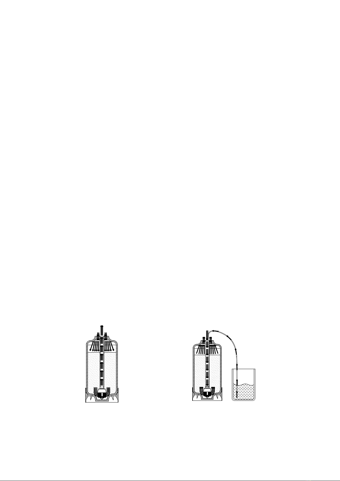
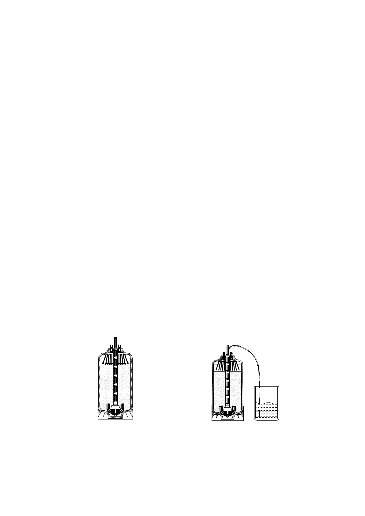
PRINCIPIO DI FUNZIONAMENTO
Come avviene l’addolcimento:
l’acqua dura viene fatta passare attraverso uno strato di resine scambiatrici di ioni che hanno la proprietà di trattenere i
sali incrostanti (calcio e magnesio) e di sostituirli con altri non incrostanti (sodio).
Quando le resine saranno sature, per rigenerarle sarà sufficiente lavarle con una soluzione di cloruro di sodio (sale
alimentare). Avverrà così un nuovo scambio ma in senso inverso al precedente, per cui alla fine dell’operazione le resine
saranno nuovamente pronte a fornire altra acqua addolcita.
Tutto ciò avverrà automaticamente.
FLUSSO IN SERVIZIO (EQUICORRENTE) FLUSSO IN RIGENERAZIONE
(CONTROCORRENTE)

cod.W010771-rev.1 Pag. 5 05/06/2021
L’apparecchiatura è comandata da una valvola automatica a fasi operative:
1. SERVIZIO
2. F2 – LAVAGGIO RESINE
3. F3 – ASPIRAZIONE SALAMOIA
4. F4 – REINTEGRO SALAMOIA
5. F5 – LAVAGGIO FINALE
CONNESSIONI IDRAULICHE
Connessioni acqua: 3/4” BSP Maschio.
Scarico: a portagomma per tubo con Ø 12 interno.
Salamoia: raccordo per tubo 3/8”
DATI TECNICI
Pressione di esercizio: min.1,5 Bar – max. 6 Bar
Temperatura acqua di esercizio: min. 5°C – max. 50°C
Alimentazione elettrica: 240Vac – 50Hz / 60Hz
Portata massima: 1m3/h (a 3bar)
INSTALLAZIONE E MESSA IN FUNZIONE
L’installazione deve essere effettuata nel rispetto delle norme nazionali vigenti, da personale professionalmente
qualificato ed abilitato, seguendo le istruzioni del Costruttore indicate nel presente manuale.
Un’errata installazione può causare danni all’ambiente, animali, persone e cose, per i quali il Costruttore non può essere
considerato responsabile.
APERTURA DELL’IMBALLO
L’apertura del cartone, contenente l’addolcitore, con attrezzi impropri può causare danni all’apparecchio.
Dopo aver liberato l’addolcitore dall’imballo, assicurarsi dell’integrità dell’apparecchio. In caso di dubbio o di danni NON
UTILIZZARLO e rivolgersi al Distributore od al Costruttore. Tutti gli elementi dell’imballaggio (sacchetti, cartone,
polistirolo espanso, griffe, regge, ecc.) non devono essere lasciati alla portata dei bambini in quanto potenziali fonti di
pericolo.
POSIZIONAMENTO DELL’IMPIANTO E COLLEGAMENTI
Durante questa operazione è bene considerare che un comodo posizionamento è vantaggioso quando si dovranno
effettuare le manutenzioni, le eventuali riparazioni ed il periodico caricamento del contenitore del sale.
La valvola è stata progettata per funzionare con temperatura ambiente compresa tra 5°C e max. 50°C max. L’eccessivo
calore ed il gelo danneggiano gravemente l’apparecchio.
La sicurezza elettrica di questo addolcitore automatico è raggiunta soltanto quando lo stesso è collegato come previsto
dalle vigenti norme nazionali di sicurezza, da personale professionalmente qualificato ed abilitato.
Il Costruttore non può essere considerato responsabile per eventuali danni causati dalla mancanza del rispetto delle
normative vigenti.
cod.W010771-rev.1 Pag. 6 05/06/2021
Addolcitore con rigenerazione a Tempo-Volume
POSIZIONAMENTO:
Adottare un luogo di posizionamento ben riparato e non esposto alle intemperie in quanto pioggia, neve,
eccessiva umidità o eccessivo irraggiamento solare, possono causare danni all’apparecchio. Il costruttore non
è responsabile di eventuali danni o malfunzionamenti dovuti al cattivo posizionamento dell’apparecchio
stesso. I materiali, in questi casi specifici non sono coperti da garanzia.
Assicurarsi che l’intero impianto di alimentazione idrica e l’impianto di scarico siano stati completati e ripuliti da
eventuali scarti di lavorazione rimasti all’interno delle tubazioni (i detriti possono essere causa di gravi danni
all’apparecchio). Si consiglia, in ogni caso di installare un pre-filtro a monte dell’apparecchio.
Prevedere l’installazione di un riduttore di pressione sulla tubazione di ingresso dell’acqua nel caso la pressione
di rete superi i 5bar (pressioni eccessive possono causare una rottura dell’intero apparato).
Prevedere l’installazione di una valvola di non ritorno a valle dell’apparecchio in modo tale da prevenire ritorni e
contropressioni (indispensabile nel caso si alimenti un boiler in quanto un ritorno di acqua calda dallo stesso
comprometterebbe l’intero apparato)
Prevedere l’installazione di un by-pass che colleghi l’ingresso e l’uscita della valvola, utile nel caso siano
necessari interventi di manutenzione sull’apparecchio. Il by-pass, in posizione di deviazione, alimenterà l’intero
impianto con acqua non addolcita, ma ne garantirà comunque l’utilizzo durante il periodo di manutenzione.
I collegamenti idrici dovranno essere fatti con tubazioni flessibili ed i fissaggi di tenuta tra i raccordi o le riduzioni
(se necessarie) con del solo Teflon®. Non applicare coppie di serraggio eccessive al fine di non danneggiare
componenti della valvola.
Il raccordo di scarico della valvola e l’eventuale raccordo di troppo pieno del tino salamoia, dovranno essere
equipaggiati con tubi flessibili da posizionare nei bacini di scarico ad un livello inferiore rispetto ai raccordi
stessi. Assicurarsi anche che i tubi non siano piegati od ostruiti e che non presentino strozzature. In aggiunta è
bene prevedere che gli scarichi avvengano direttamente a sifone aperto.
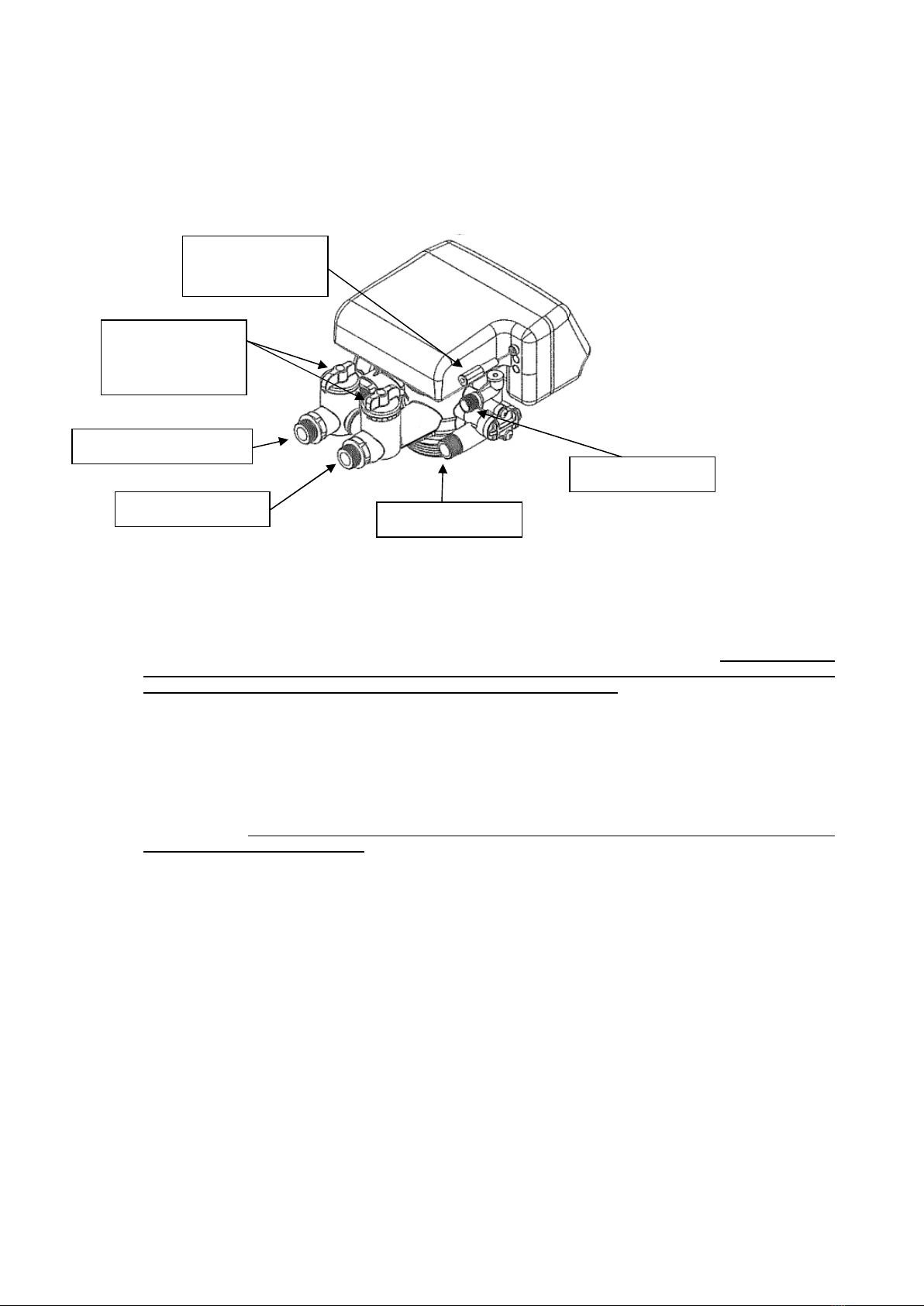
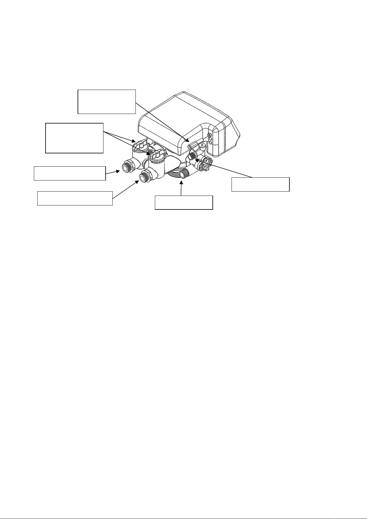
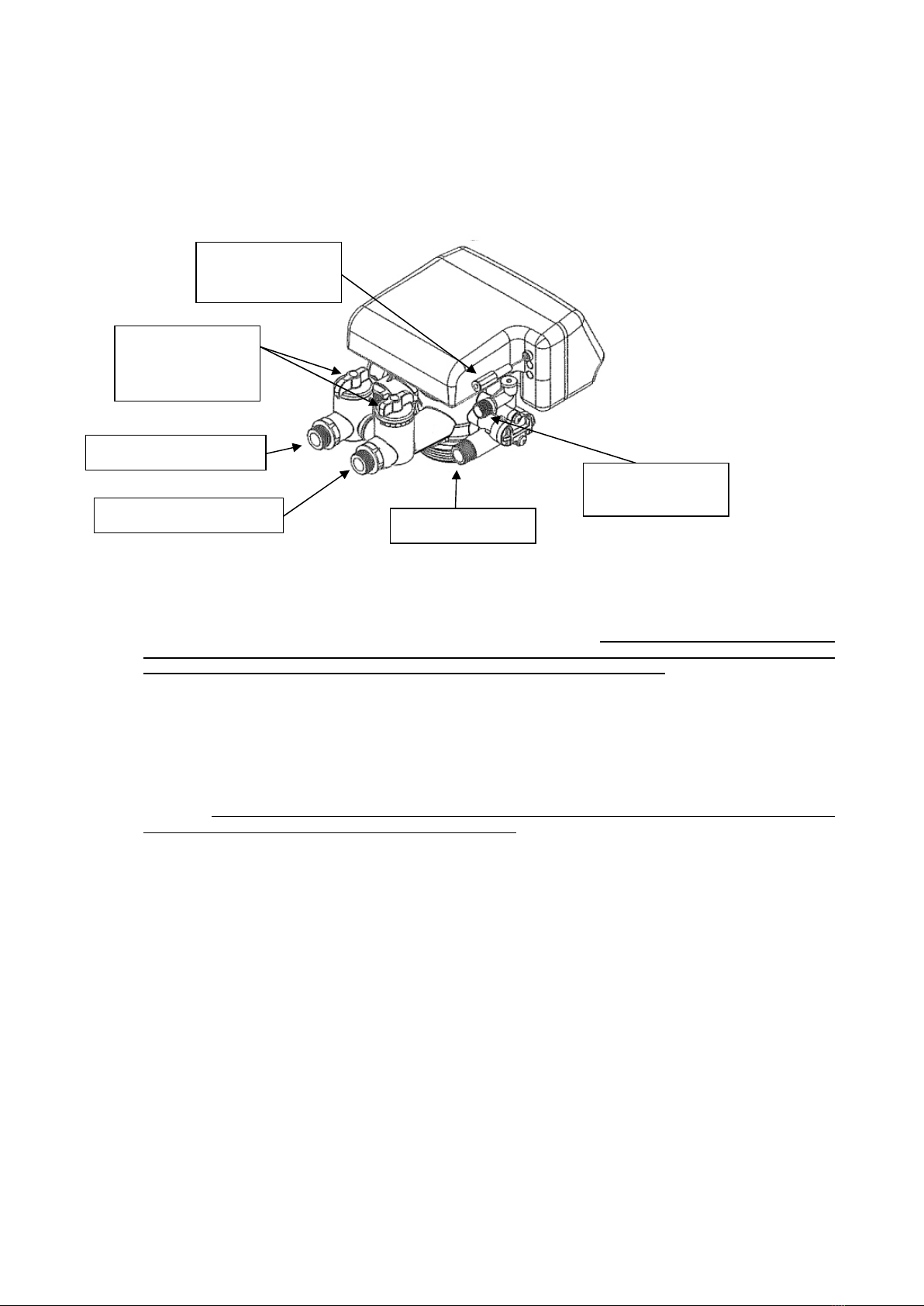
MISCELAZIONE DUREZZA IN USCITA / BYPASS
I rubinetti di entrata-uscita vengono forniti nella posizione “0”, equivalente al massimo addolcimento. È possibile
miscelare l’acqua in uscita con quella in entrata aprendo i rubinetti nelle varie posizioni, da “1 a 8”. Entrambi i rubinetti
nella posizione 8 escludono l’addolcimento dell’acqua.
ENTRATA ACQUA ¾”
USCITA ACQUA ¾”
SCARICO ¾”
TUBO SALAMOIA
COLLEGAMENTO
ELETTRICO
MISCELAZIONE
BYPASS
cod.W010771-rev.1 Pag. 7 05/06/2021
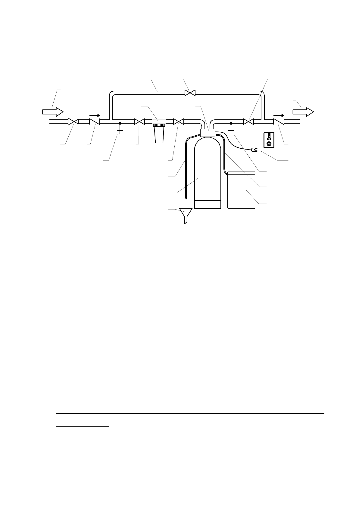
SCHEMA DI COLLEGAMENTO IDRAULICO ED ELETTRICO
COLLEGAMENTI ELETTRICI
Assicurarsi che la presa di alimentazione elettrica a cui è collegato il trasformatore della valvola, non sia
comandato da un interruttore generale a monte.
E’ indispensabile predisporre, per una corretta e sicura installazione dell’addolcitore, una apposita presa in
prossimità dell’apparecchio in modo tale da essere in caso di necessità facilmente raggiungibile.
Non improvvisare alcuna riparazione od intervento diretto ma rivolgersi a personale professionalmente
qualificato. In caso di danneggiamento del cavo di alimentazione, spegnere l’apparecchio e, per la sostituzione,
affidarsi esclusivamente a personale professionalmente qualificato.
Tutti i dispositivi elencati dovranno essere conformi alle norme nazionali vigenti in materia, il
costruttore non è da ritenersi responsabile per impianti non eseguiti a regola d’arte e alla mancanza del
rispetto delle norme.
H
K L
M
N
O
N
F
G
B
C
N
M
E
J N
L
I
P
D
B
= Bombola contenitore resine
C= Valvola per addolcimento
D= Tubo pescaggio rigenerante
E= Contenitore rigenerante (salamoia)
F= Tubo di scarico
G
= Pozzetto scarico a sifone aperto
I
= Uscita acqua t
rattata (addolcita)
J= Tubazione By-Pass
K= Riduttore di pressione (necessario per
pressioni superiori a 5bar)
L= Valvola di non ritorno
M
= Rubinetto di prelievo per analisi
cod.W010771-rev.1 Pag. 8 05/06/2021
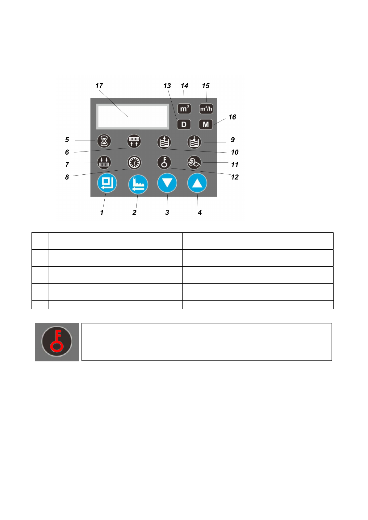
DISPLAY
1 Menù parametri / conferma 10 Aspirazione salamoia fase 3
2 Rigenerazione manuale / exit 11 Settaggio
3 Tasto giù 12 Display bloccato
4 Tasto su 13 Giorni
5 Addolcitore in servizio 14 Capacità acqua trattata restante (m^3)
6 Lavaggio resine fase 2 15 M^3/h in servizio
7 Lavaggio veloce resine fase 5 16 Ora rigenerazione
8 Orario 17 Display
9 Ripristino Salamoia fase 4
AVVIAMENTO
Quando si avvia per la prima volta l’apparecchio è necessario:
Aprire il rubinetto che alimenta l’addolcitore
Aprire un rubinetto all’utilizzo affinché fuoriesca l’aria dalle condutture e si lavino le resine. L’acqua che ne
fuoriesce potrebbe, per qualche minuto, presentarsi di colorazione scura. Prima di utilizzarla lasciarla scaricare
finché non sarà “pulita”.
Controllare che non vi siano perdite dai collegamenti idraulici
Collegare lo spinotto del trasformatore all’apposita presa posta nella parte posteriore della valvola
Alla prima accensione attendere che la valvola si metta nella posizione di servizio, il display indica “-00-“
Impostare l’orario: premendo il tasto 1 si entra in programmazione e il primo parametro che si trova è l’orario.
Per modificarlo, premere il tasto 1 e scegliere l’ora con i tasti 3 e 4. Premere il tasto 1 per passare ai minuti,
scegliere il valore corretto con i tasti 3 e 4. Una volta finito, premere il tasto 1 per confermare, poi il tasto 2 per
uscire dalla programmazione.
ATTENZIONE: quando l’indicatore 12 è accesso, il display è BLOCCATO
Per sbloccarlo, premere insieme i tasti 3 e 4 per 5 secondi
cod.W010771-rev.1 Pag. 9 05/06/2021
Caricare di acqua il tino del sale. Versare nel contenitore del sale un litro di acqua per ogni litro di resina
contenuta nella bombola dell’addolcitore. (Esempio: per un addolcitore da 8 lc. di resina si dovranno mettere 8
litri di acqua). Successivamente l’acqua verrà caricata in modo completamente automatico
Riempire il contenitore del sale per 3/4 della sua capienza con SALE (è consigliato sale in PASTIGLIE in
quanto presenta meno impurità del sale grosso)
PARAMETRI
Per accedere ai parametri della valvola:
Sbloccare il display premendo contemporaneamente i tasti 3 e 4 per 5 secondi
Premere il tasto 1 per accedere ai parametri
Premere i tasti 3 e 4 per scorrere i parametri, per modificare un parametro premere il tasto 1. Scegliere il valore
con i tasti 3 e 4, per confermare premere il tasto 1
Per uscire dalla programmazione premere il tasto 2
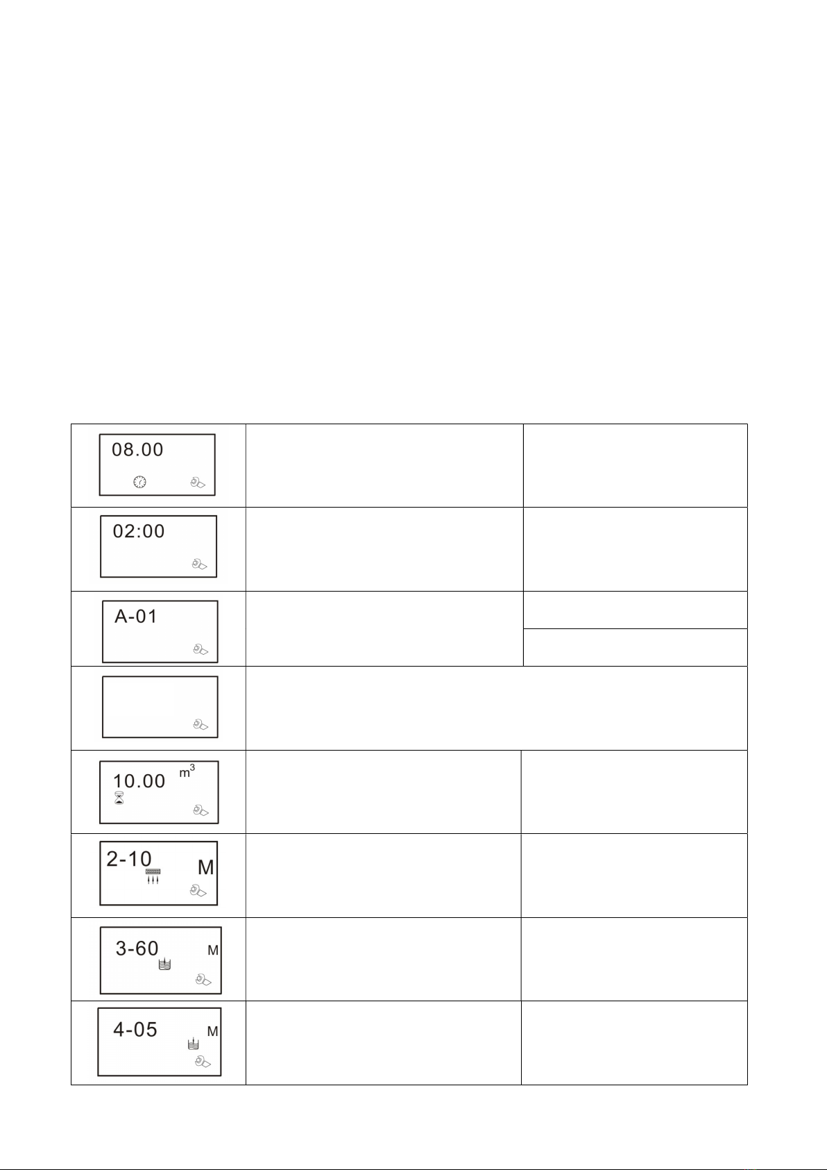
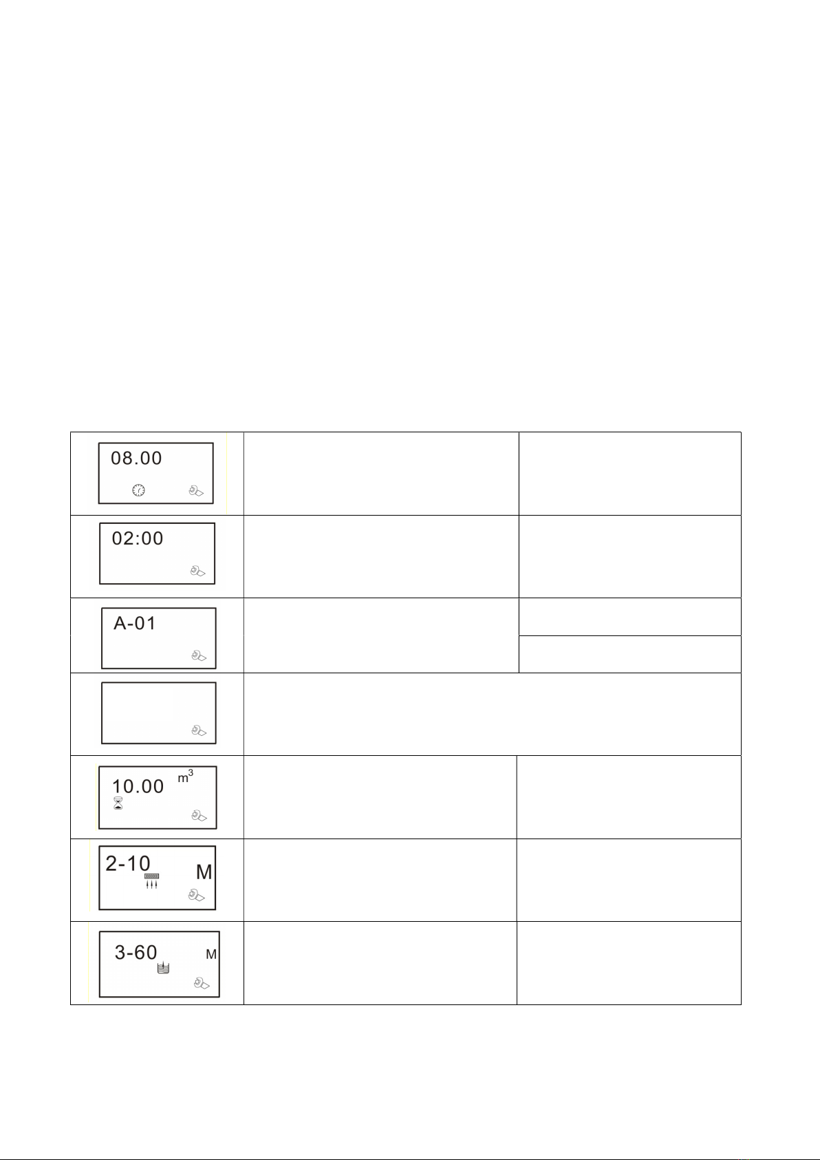
LISTA PARAMETRI
Orario del giorno 00:00 – 23:59
Orario di rigenerazione 00:00 – 23:59
Modalità di rigenerazione
Settaggio A-01
A-01: una volta finito il volume d’acqua trattabile,
la rigenerazione avviene all’orario di
rigenerazione impostato
A-02: una volta finito il volume d’acqua trattabile,
la rigenerazione parte immediatamente
PER IL CORRETTO FUNZIONAMENTO DELLA VALVOLA, LASCIARE IL
PARAMETRO IMPOSTATO F-00
Capacità di acqua addolcita 0 – 99.99 m3
Fase 2 : lavaggio resine 0 – 99 min.
Fase 3 : Aspirazione salamoia 0 – 99 min.
Fase 4 : Ripristino salamoia 0 – 99 min.
F-00
cod.W010771-rev.1 Pag. 10 05/06/2021
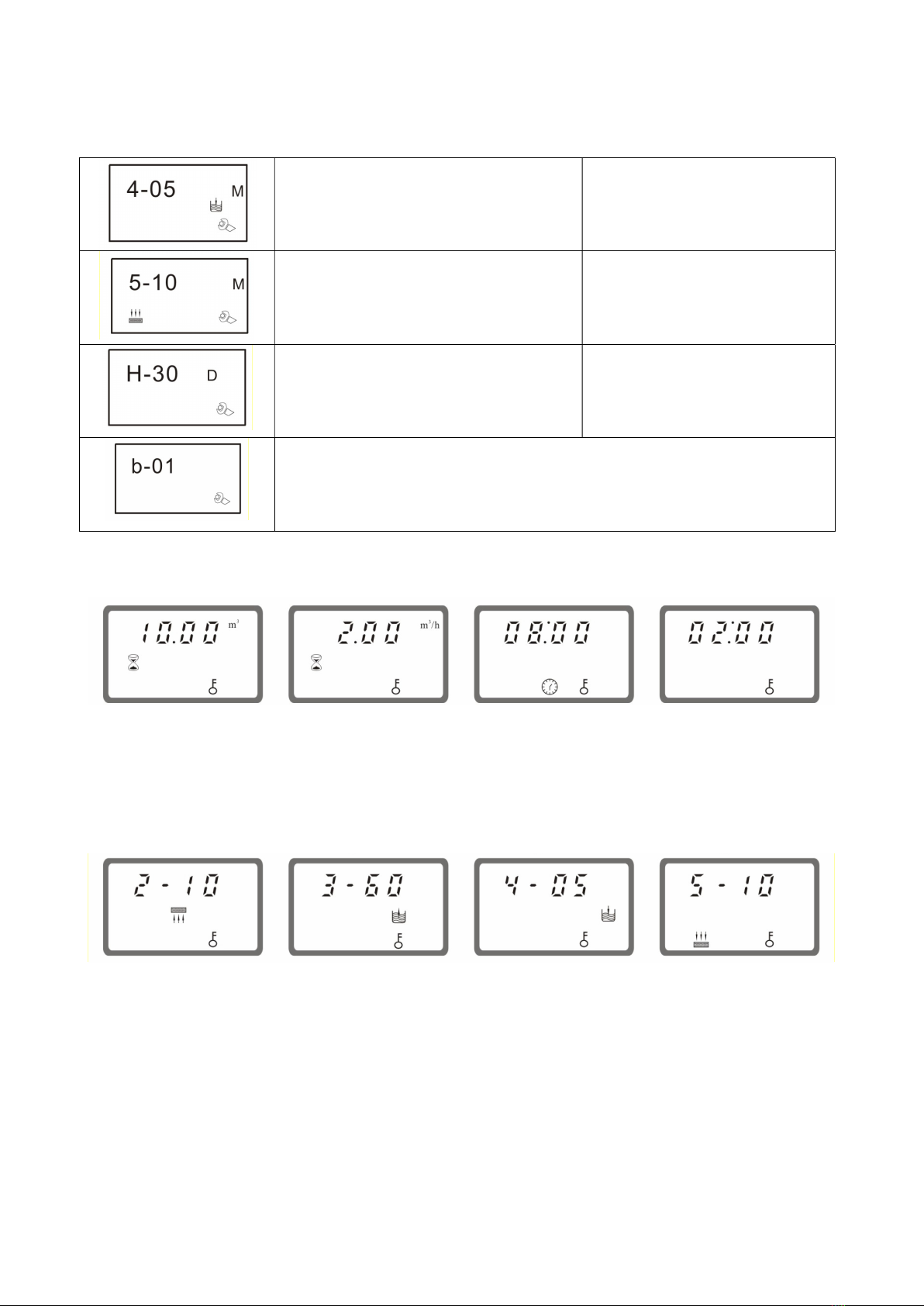
Fase 5 : lavaggio e ricompattamento resine 0 – 99 min.
Intervallo giorni massimi di rigenerazione
0 – 40 giorni
Intervallo di Rigenerazione all’ora
impostata anche se il volume di
acqua erogabile non è esaurito
PER IL CORRETTO FUNZIONAMENTO DELLA VALVOLA, LASCIARE IL
PARAMETRO IMPOSTATO B-01
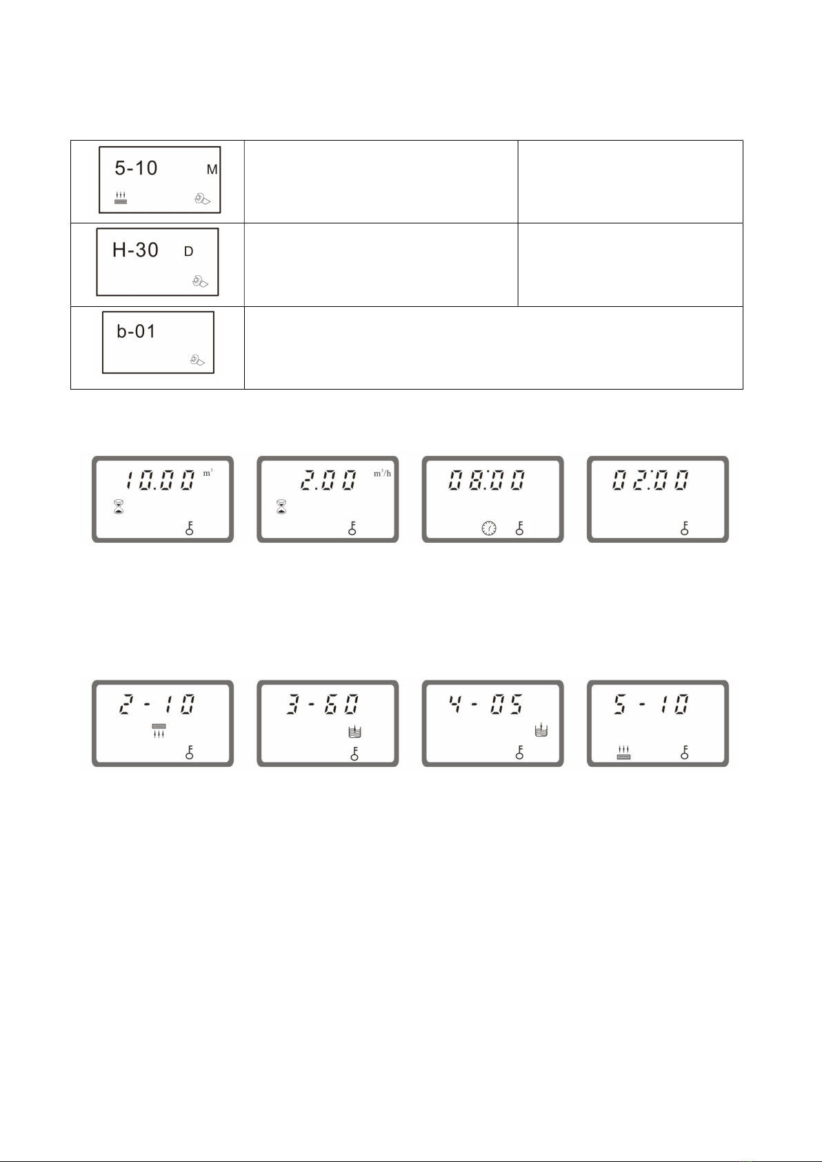
VISUALIZZAZIONE DEL DISPLAY
Mentre l’addolcitore è in servizio il display visualizza ad oltranza i seguenti dati:
Volume d’acqua addolcita restante al momento della visualizzazione
Portata d’acqua in m3/h al momento della visualizzazione
Orario del giorno al momento della visualizzazione
Orario di rigenerazione impostato nei parametri
Durante la rigenerazione il display indica inoltre la fase che si sta compiendo con il tempo rimanente al momento della
visualizzazione
RIGENERAZIONE MANUALE
È possibile eseguire una rigenerazione manuale in qualsiasi momento del servizio. Sbloccare il display tenendo premuto
i tasti 3 e 4 per 5 secondi, poi premere il pulsante 2.
cod.W010771-rev.1 Pag. 11 05/06/2021
INSTALLATION
This instructions manual is an integrating part of the automatic valve for water softening (also defined in this instructions
manual, more simply with the terms of valve or appliance) and must be kept for any future consultation. Carefully read
the warnings contained in this manual before installing and using the valve. These warnings have been drawn up for the
safe installation, use and maintenance; any warnings or diagrams relating to particular models, will be provided attached
to this instructions manual. Any intervention to the electrical system or hydraulic system must be carried out by qualified
and enabled staff only.
Any use of the valve different from the production of softened water, using water at temperatures above 50° is to be
considered improper. To guarantee valve efficiency and for its correct functioning, it is essential to comply with the
Manufacturer indications having installation and repairs carried out by qualified staff, as the intervention of inexperienced
persons, can cause or worsen damages, as well as be dangerous.
We recommend to always pretend original spare parts.
When foreseeing the demolishing of the appliance, it is advised to make it unusable and dispose of it and recover the
materials, in accordance with the relative national dispositions in force.
In order to avoid damaging the valve, it is necessary to transport, store and handle the appliance, only in vertical position,
respecting the indications on the packaging.
MAIN FEATURES
CONTENT OF THE PACKAGE AND OPTIONAL ACCESSORIES
n°1 Softner
n°1 Use and maintenance manual (this manual)
n°1 Transformer In – 230Vac Out 24Vac – 50/60Hz
FUNCTIONING PRINCIPLE
How softening happens:
Hard water is made to go through a layer of ions exchanger resins which properties withhold the encrusting salts
(calcium and magnesium) and replace them with others non-encrusting (sodium).
When the resins are saturate, wash them in a sodium chloride (food salt) solution to regenerate them. An inverted
exchange happens to previous, therefore, at the end of the operation, the resins will be ready again to supply more
softened water.
All this happens automatically.
SERVICE FLOW ((PARALLEL FLOW) REGENERATION FLOW
(COUNTERFLOW)

cod.W010771-rev.1 Pag. 12 05/06/2021
The equipment is controlled by an operational phases automatic valve:
1. SERVICE
2. F2 – BACKWASH RESIN
3. F2 – BRINE AND SLOW RINSE
4. F3 – BRINE FILL
5. F4 – FAST RINSE
HYDRAULIC CONNECTIONS
Water connections: 3/4” BSP Male
Discharge: with hose-end fitting for hose with Ø 12 inside.
Brine: fitting for 3/8" hose
TECHNICAL DATA
Working pressure: min. 1.5bar – max. 6bar
Working water temperature: min. 2°C – max. 50°C
Electric power supply: 230Vac – 50Hz with output voltage from transformer at 24Vac
Maximum capacity: 1m3/h (at 3bar)
INSTALLATION AND COMMISSIONING
Installation must be carried out in compliance with the national standards in force, by professionally qualified and enabled
staff, following the Manufacturer instructions given in this manual.
An incorrect installation can cause damages to the environment, animals, persons and things, which the Manufacturer
cannot be considered responsible for.
OPENING THE PACKAGING
Open the box containing the valve with unsuitable tools can damage the appliance.
After having freed the valve from the packaging, check the integrity of the appliance. If in doubt or damaged, DO NOT
USE IT and contact the Distributor or Manufacturer. None of the packaging elements (bags, cardboard, expanded
polystyrene, claws, straps, etc.) must be left within children's reach as they are a potential source of danger.
PLACING THE PLANT AND CONNECTIONS
A comfortable placement is advantageous when having to carry out maintenance, any repairs and periodical loading of
the salt container.
The valve has been designed to work at an environmental temperature between 2°C and max. 40°C. Excessive heat and
frost seriously damage the appliance.
The automatic valve is electrically safe only when it is connected as foreseen by the national safety standards in force
and by professionally qualified and enabled staff.
The Manufacturer cannot be considered responsible for any damages caused by the non-compliance with the current
legislations.
cod.W010771-rev.1 Pag. 13 05/06/2021
Softeners with chrono-volumetric regeneration
POSITIONING:
• Ensure the entire water supply system and discharge system have been completed and cleaned from any
working residues inside the piping (debris can seriously damage the appliance). We recommend installing a pre-filter
upstream of the appliance.
• Foresee the installation of a pressure reducer on the water inlet piping in the event the network pressure
exceeds 5bar (excessive pressures can break the entire apparatus).
• Foresee the installation of a check valve downstream of the appliance to prevent returns and back pressures (it
is essential in the event of supplying a boiler, as a hot water return from the same, would jeopardise the entire
apparatus).
• Foresee the installation of a by-pass connecting the valve input and output, that is useful in the event of
appliance maintenance interventions. The by-pass in diverter position, supplies the full plant with not softened water, but
will guarantee its use during the maintenance period.
• The water connections must be made with flexible piping and the seals between the fittings or reductions (if
necessary) with Teflon® only. Do not apply excessive fastening torques to avoid any damages to the valve components.
• The discharge fitting of the valve and any too full fitting of the brine vat, must be equipped with flexible hoses to
be positioned in the discharge basins at a lower level to the same fittings. Ensure that the hoses are not bent, obstructed
or choked. In addition, discharge must happen directly with open siphon.
OUTLET WATER HARDNESS MIXING / BYPASS
The inlet-outlet taps are supplied in the “0” position, equivalent to maximum softening. It is possible to mix the outgoing
water with the incoming water by opening the taps in the various positions, from "1 to 8". Both taps in position 8 exclude
water softening.
INLET WATER ¾”
OUTLET WATER ¾”
DRAIN ¾”
BRINE TUBE
ELECTRICAL
CONNECTION
MIXER
BYPASS

cod.W010771-rev.1 Pag. 14 05/06/2021
RECOMMENDED HYDRAULIC-ELECTRICAL CONNECTIONS:
ELECTRIC CONNECTIONS:
Ensure the electric power supply plug, which the valve transformer is connected to, is not controlled by an
upstream main switch. For the correct function, the valve must be constantly powered.
For the correct and safe installation of the softener, it is essential to set-up a specific plug near the appliance so
that it is easily reachable, if required.
Do not attempt any direct intervention or repair but contact professionally qualified staff. If the power supply
cable is damaged, switch-off the appliance and contact only professionally qualified staff for its replacement.
All listed devices must be conform to the relative national standards in force; the manufacturer is not to be
considered responsible for plants that are not correctly executed and non-compliance with the standards.
Fig. 1
H
K L
M
N
O
N
F
G
B
C
N
M
E
J N
L
I
P
D
B
= Resin container cylinder
C = Valve for softening
D = Regenerant pick-up hose
E = Regenerant container (brine)
F = Discharge hose
G
= Open siphon discharge sump
I
= Treated water outlet (s
oftened)
J = By-Pass piping
K = Pressure reducer (necessary for
pressures above 7bar)
L = Check valve
M
= Draw
-
off tap for analysis

cod.W010771-rev.1 Pag. 15 05/06/2021
DISPLAY
1 Parameters menù/confirm 10 Brine e slow rinse phase 3
2 Manual Regeneration / exit 11 Setting
3 Down button 12 Button lock
4 Up button 13 Day
5 Service 14 Water treated capacity (m^3)
6 Backwash phase 2 15 M^3/h in service
7 Fast rinse phase 5 16 Regeneration time
8 Time 17 Display
9 Brine refill phase 4
START-UP
When commissioning the appliance it is necessary:
Open the cock supplying the softener.
Open a cock for air inside the ducts bleeds and the resins are washed. The outlet water may, for a few minutes,
be dark coloured. Leave it to run until is “cleaned”, before using it.
Check for leaks from the hydraulic connections.
Connect the transformer plug to the specific socket in the rear part of the valve.
When switching on for the first time, wait that the valve goes to the service position, the display indicates “-00-“
Set the time: by pressing key 1 you enter on menù and the first parameter found is the time. To modify it, press
key 1 and choose the hour with keys 3 and 4. Press key 1 to move to the minutes, choose the correct value with
keys 3 and 4. Once finished, press key 1 to confirm, then key 2 to exit programming.
WARNING
:
when the indicato
r 12 lights on, the buttons are locked
For unlocked, press and hold the button 3 and 4 for 5 seconds
cod.W010771-rev.1 Pag. 16 05/06/2021
Fill the salt tank with water. Put a liter of water into the salt tank for each liter of resin contained in the softener
bomb. (Example: 8 liters of water should be added for an 8 lc resin softener). Subsequently, the water will be
loaded fully automatically
Fill 3/4 of the salt container with SALT (salt in PADS is recommended as it has less impurities than coarse salt).
PARAMETERS
For enter on the parameters menù:
Unlock the display, press and hold the button 3 and 4 for 5 seconds
Push the button 1 for entering on the menù
Press keys 3 and 4 to scroll through the parameters, to modify a parameter press key 1. Select the value with
keys 3 and 4, to confirm press key 1
Push the button 2 for exit to the menù
PARAMETERS LIST:
Time of day 00:00 – 23:59
Regeneration time 00:00 – 23:59
Regeneration modality
Setting A-01
A-01: when the available volume drops to zero,
the regeneration will star until at regeneration
time
A-02: Regenerate immediately when the
available volume drops to zero
FOR CORRECT VALVE OPERATION, LEAVE THE SET PARAMETER F-00
Water treatment capacity 0 – 99.99 m3
phase 2 : backwash time 0 – 99 min.
phase 3 : Brine e slow rinse time 0 – 99 min.
F-00
cod.W010771-rev.1 Pag. 17 05/06/2021
phase 4 : Brine refill time 0 – 99 min.
phase 5 : Fast rinse time 0 – 99 min.
Maximum interval regeneration days
0 – 40 days
Renerate at the regeneration time even
though tha available volume of treated
water does not drop to zero
FOR CORRECT VALVE OPERATION, LEAVE THE SET PARAMETER B-01
DISPLAY VISUALIZATIONS
While the softener is in service, the display shows these informations:
Remaining water treated volume, at the showing moment
Water flow rate ( m3/h) at the showing moment
Time of day at the showing moment
Regeneration time
During regeneration, the display also indicates the phase that is taking place with the time remaining at the time of the
showing
MANUAL REGENERATION
You can perform a manual regeneration at any time of the service. Unlock the display by pressing and holding keys 3
and 4 for 5 seconds, then press key 2.
cod.W010771-rev.1 Pag. 18 05/06/2021
INSTALLATION
Cettenotice d’installation fait partie intégrante de l'adoucisseur d'eau automatique (appelée dans cettenotice, plus
simplement, adoucisseur ou dispositif) et doit être conservée pour toute référence future.
Lire attentivement les instructions contenues dans ce manuel avant d'installer et d'utiliser l'adoucisseur.
Ces avertissements sont fournis afin de garantir la sécurité durant l'installation, l'utilisation et l'entretien. Le cas échéant,
des instructions supplémentaires ou schémas relatifs à des modèles spécifiques seront fournis avec cette notice.
Toute intervention sur le système électrique ou hydraulique doit être effectuée par un personnel qualifié autorisé.
Toute utilisation de l'adoucisseur d'eau autre que la production d'eau adoucie, ou en utilisant de l'eau à une température
supérieure à 50°, est considérée comme impropre.
Afin de garantir l'efficacité de l'adoucisseur et son bon fonctionnement, il est essentiel de suivre les instructions du
fabricant en faisant effectuer l'installation et les réparations par du personnel qualifié. L'intervention de personnes non
qualifiées, outre être dangereuse, peut causer ou aggraver les dommages.
Nous recommandons de toujours utiliser des pièces de rechange originales.
Au moment de démanteler le dispositif, il est recommandé de le mettre hors service et d'organiser son élimination et la
récupération des matériaux conformément à la réglementation nationale.
Afin d'éviter d'endommager le dispositif, il est nécessaire de le transporter, de le stocker et de le manipuler en position
verticale exclusivement, en respectant les indications fournies sur l'emballage.
CARACTÉRISTIQUES GÉNÉRALES
CONTENU DE L'EMBALLAGE ET ACCESSOIRES EN OPTION
1 Adoucisseur d'eau automatique
1 Manuel de l'utilisateur (ce manuel)
1 Transformateur Entrée - 230 Vac Sortie 24 Vac - 50/60 Hz
PRINCIPE DE FONCTIONNEMENT
Comment fonctionne l'adoucissage :
L’eau dure passe à travers une couche de résines échangeuses d'ions dont la propriété est de retenir les sels
incrustants (calcium et magnésium) et de les remplacer par d'autres non-incrustants (sodium).
Lorsque les résines sont saturées, il suffit de les laver pour les régénérer en utilisant une solution de chlorure de sodium
(sel de table). Un nouvel échange sera alors effectué dans la direction opposée au précédent, permettant ainsi à la
résine de fournir à nouveau de l'eau adoucie une fois l'opération terminée.
Cette opération est effectuée automatiquement.
FLUX EN SERVICE (ÉQUICOURANT) FLUX EN MODE RÉGÉNÉRATION
(CONTRE-COURANT)

cod.W010771-rev.1 Pag. 19 05/06/2021
Le dispositif est commandé par une vanne automatique à phases de fonctionnement :
1. SERVICE
2. F2 – LAVAGE RESIN
3. F3 - ASPIRATION SAUMURE
4. F4- RÉINTÉGRATION SAUMURE
5. F5 – LAVAGE FINAL
RACCORDEMENTS HYDRAULIQUES
Raccordements hydrauliques : 3/4" BSP Malle.
Évacuation : avec raccord pour tuyau, Ø interne 12.
Saumure : raccord pour tuyau 3/8"
DONNÉES TECHNIQUES
Pression de fonctionnement : min. 2 bars – max. 6 bars
Température de l'eau en service : min. 2°C – max. 50°C
Alimentation électrique : 230Vac - 50 Hz avec tension de sortie du transformateur à 24 Vac
Débit maximum : 1m3/h (à 3 bars)
INSTALLATION ET MISE EN SERVICE
L'installation doit être effectuée conformément à la réglementation nationale, par des professionnels qualifiés et
autorisés, en suivant les instructions du fabricant fournies dans ce manuel.
Une mauvaise installation peut provoquer des dommages vis-à-vis de l'environnement, des animaux, des personnes et
des biens, pour lesquels le fabricant n'acceptera aucune responsabilité.
OUVERTURE DE L'EMBALLAGE
L'ouverture du carton contenant l'adoucisseur avec des outils non adaptés peut endommager le dispositif.
Après avoir sorti l'adoucisseur de son emballage, vérifier qu'il soit en bon état. En cas de doute ou en présence de
dommages, NE PAS L'UTILISER et contacter le distributeur ou le fabricant. Les éléments utilisés pour l'emballage
(sachets, carton, mousse de polystyrène, cales, etc.) ne doivent pas être laissés à la portée des enfants car ils
constituent des sources potentielles de danger.
POSITIONNEMENT DU SYSTÈME ET BRANCHEMENTS
Durant cette opération, il est important de choisir un emplacement pratique pour effectuer les interventions d'entretien,
réparations ou encore le chargement périodique du réservoir de sel.
La vanne a été conçue pour fonctionner à une température ambiante comprise entre 5°C et 50°C. Une chaleur
excessive et le gel endommagent gravement le dispositif.
La sécurité électrique de cet adoucisseur d'eau automatique n'est garantie que lorsque celui-ci est branché
conformément aux normes de sécurité nationales en vigueur et par des professionnels qualifiés et autorisés.
Le fabricant ne saura être tenu responsable en cas de dommages causés par le non-respect de la réglementation.
cod.W010771-rev.1 Pag. 20 05/06/2021
Adoucisseur avec régénération à temps et volume.
POSITIONNEMENT :
Choisir un emplacement bien protégé et non exposé aux intempéries telles que la pluie, la neige, l'humidité ou
rayonnement solaire excessifs susceptibles d'endommager le dispositif. Le fabricant n'est pas responsable
des dommages ou dysfonctionnements dus à un mauvais positionnement du dispositif. En cas de
positionnement inadapté, les matériaux ne seront pas couverts par la garantie.
Vérifier que l'installation du système d'approvisionnement en eau et du système d'évacuation a été achevée et
qu'il ne reste pas de dépôts dans les tuyaux (les détritus peuvent gravement endommager le dispositif). Il est
dans tous les cas recommandé d'installer un préfiltre en amont du dispositif.
Prévoir l'installation d'un réducteur de pression sur le tuyau d'entrée d'eau si la pression d'alimentation est
supérieure à 5 bars (des pressions excessives peuvent provoquer une rupture du dispositif).
Prévoir l'installation d'un clapet anti-retour en aval du dispositif de façon à empêcher les retours et contre-
pressions (indispensable en cas d'alimentation d'un chauffe-eau sachant qu'un retour d'eau chaude en
provenance de ce dernier pourrait endommager le dispositif).
Prévoir l'installation d'un système de dérivation reliant l'entrée et la sortie de la vanne. Ceci est utile pour les
interventions d'entretien nécessaires du dispositif. Le système de dérivation, une fois activé, alimentera
l'ensemble du système avec de l'eau non traitée, mais en garantira toutefois l'utilisation durant la période de
maintenance.
Les raccordements d'eau doivent être effectués en utilisant des tuyaux flexibles, et les joints entre les raccords
ou les réductions (si nécessaires) doivent être en Téflon® uniquement. Ne pas appliquer de couples de serrage
excessifs afin de ne pas endommager les composants de la vanne.
Le raccord d'évacuation de la vanne et l'éventuel raccord de débordement du réservoir de saumure doivent être
équipés de tuyaux flexibles installés dans les cuves d'évacuation à un niveau inférieur par rapport aux raccords
eux-mêmes. Vérifier également que les tuyaux ne sont ni pliés ni obstrués, et qu'ils ne présentent pas de
goulots d'étranglement. De plus, il est recommandé que les évacuations se fassent directement à siphon
ouvert.
MIXAGE DE LA DURETE DE l’EAU EN SORTIE / BYPASS
Les robinets d’entrée-sortie sont livrés d’origine en position “0”, ce qui équivaut à un adoucissement maximal.
Il est possible de mélanger l’eau sortante avec l’eau entrante en ouvrant les robinets dans les différentes positions, de
« 1 » à « 8 ». Les deux robinets en position 8 contemporaines excluent l’adoucissement de l’eau.
ENTRÉE D'EAU
¾”
SORTIE D'EAU
¾”
ÉVACUATION
¾”
ASPIRATION
SAUMURE
CONNEXION
ÉLECTRIQUE
MIX
BYPASS
Table of contents
Languages:


