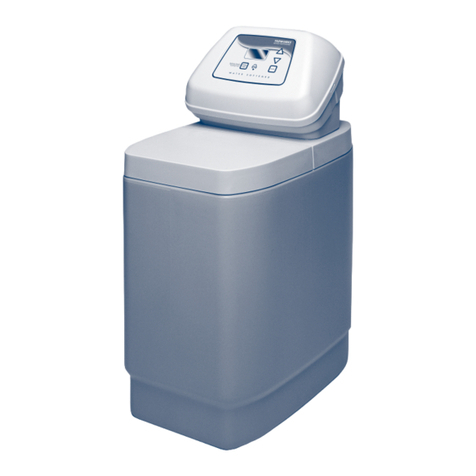
Tapworks Ultra 9 Manual

User and Installer Handbook
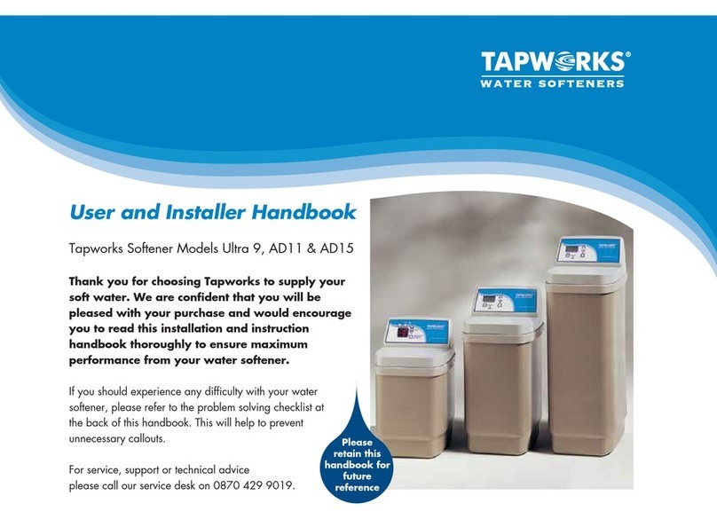
Tapworks Softener Models Ultra 9, AD11 & AD15
Thank you for choosing Tapworks to supply your
soft water. We are confident that you will be
pleased with your purchase and would encourage
you to read this installation and instruction
handbook thoroughly to ensure maximum
performance from your water softener.
If you should experience any difficulty with your water
softener, please refer to the problem solving checklist at
the back of this handbook. This will help to prevent
unnecessary callouts.
For service, support or technical advice
please call our service desk on 0870 429 9019.
Please
retain this
handbook for
future
reference


Identifying major parts of your water softener
Please Remember – Only use tablet or pellet salt in your softener! 2
1Control Valve Cover and Electronic Faceplate
2Salt Lid
3Salt Cabinet
4Water Softener Valve and Motor
5Brine Well and Cover
6Overflow Connection
7Rim
Note
Serial Number is required for registration
of warranty (located under salt lid).
Installation of Tapworks Softener models Ultra 9, AD11 & AD 15
1
4
6
3
5
2
7

Identifying major parts of your water softener
(cont)
3
Easy Install Tees 1pair G1038
(incorporates check valve)
By pass set (3 valves) 1 set B505 (1)
B534 (2)
15mm reducer (if required) 2 39845
Inlet/Outlet Hoses 2 803189
Hose Gaskets 4 803188
Adaptor Elbows 2 7255583
Description Quantity
Installation of Tapworks Softener models Ultra 9, AD11 & AD 15
(with prefitted adaptor ‘O’ rings)
Adaptor Clips 1pair 7109041
Silicone Grease 1 n/a
Drain & Overflow Tubing 1 10069
Overflow Elbow 1 7109041
Overflow Grommet 1 7109041
Drain & Overflow hose clips 2 7109041
Transformer 1 7323679
Hard Water Test Kit 1 800005
Spares-Adaptor ‘O’ Rings 2 7109041
Please Remember – Only use tablet or pellet salt in your softener!

Installation of your water softener (cont)
4
PLANNING AND SITING THE INSTALLATION
The installation of a water softener is relatively easy, but we
recommend that this work is undertaken by a plumber or an
experienced DIY handyman. Where possible the water softener
should be sited close to the rising main, allowing for any required
hard water draw off points, i.e. drinking tap and outside tap.
A 22mm installation kit is included with the water softener. Use the
15mm reducers for 15mm pipework. Keep the drain run as short as
possible and allow for ease of service and salt access. If installed
next to a boiler or hot water cylinder you may have to protect
against condensation. When siting the softener please place on a
sound base and consider space for accessing the unit for servicing
etc. Sufficient space should be left behind the unit to allow easy
access for repairs and cleaning. A minimum of 3” space must be
left above thevalve cover lid.Check local plumbing and electrical
regulations and by-laws. The installation must conform to them.
FREEZING
The installation of all water fittings should be in accordance with
local water bylaws and the water softener, and all associated
pipework, must be protected against freezing. Take special care
where the drain runs outside. Freezing will prevent recharge and
cause overflowing.
LEAD PIPEWORK
Where lead pipework exists downstream of the proposed location
of the water softener, we advise you ask the local water authority
for advice on the replacement of lead pipework. Grants may be
available. Homes built since 1976 will not have lead pipework.
ELECTRICAL REQUIREMENTS
The water softener requires a 240 volt 50 Hz electrical supply
taken off a power supply not a lighting circuit. Power is supplied via
a 24 volt 50 Hz transformer.
HARDWATER TAP
Fitting a separate hard water drinking water tap is
currently recommended by the UK Dept of
Health,WRAS and the UKWTA.
Fitment of separate hard water drinking tap is not required by
regulation, except in exceptionally hard water areas
(above 400mg/l) where the Sodium content of the treated water
(increased due to the softening process) exceeds the level laid
down in the Water Supply (Water Quality) Regulations 2000.
If in doubt please seek advice.
PRESSURE
Low or high pressure could lead to damage or non-operation of the
water softener. If the daytime pressure exceeds 4.76 BAR (70 psi)
a pressure- reducing valve should be fitted. If daytime pressure is
less than 1.7 BAR (25 psi) a pressure pump is required.
Note: Night-time pressure will be much higher than daytime.
FLOW RATES
The water flow must be at least 1 litre per minute for the water
softener to operate as originally designed.
Maximum flow is 53 litres per minute (peak).
PLUMBING COMPONENTS NEEDED
The installation kit provides the basic plumbing components but
additional piping and connectors (capillary and/or compression
copper fittings) should be used as required.
WARNING: FAILURE TO MEET THE FOLLOWING
REQUIREMENTS CAN CAUSE DAMAGE TO THE WATER
SOFTENER, OR RESTRICT ITS OPERATION.
Installation of Tapworks Softener models Ultra 9, AD11 & AD 15
Please Remember – Only use tablet or pellet salt in your softener!

Installation of your water softener (cont)
SPECIFICATION REQUIREMENTS
Maximum water temperature 49°C (120°F)
Maximum daytime working pressure
4.76 BAR (70 psi)
Minimum working pressure 1.7 BAR (25 psi)
Minimum system flow 0.06m3/hr
Maximum system flow 3.18m3/hr
If a pressure-reducing valve is required this may be ordered
from Tapworks:
Quote Part No.800220 for 1/2” or 15mm pipework
Quote Part No.800223 for 3/4” or 22mm pipework
UNVENTED OR COMBINATION SYSTEMS
The water softener and installation kit is compatible with
unvented or combination systems. All connections are included
for the by-pass (two 15mm reducers are included if required).
DRAIN HOSE
With a recommended pressure of 3 BAR, the maximum drain
run is 3m with a constant fall before entering an air gap.
The maximum height above the softener should be no more
than 2m.
CENTRAL HEATING SYSTEMS
Central heating systems should always be treated with a
proprietary corrosion inhibitor regardless of being filled with
softened or hard water. Systems containing aluminium should
always be filled with hard water unless instructed otherwise by
the manufacturer.
APressure Reducing Valve (if required)
BBypass Valve
CInlet Valve
DOutlet Valve
EInlet tee incorporating check valve
A
B
D C
E
Installation of Tapworks Softener models Ultra 9, AD11 & AD 15
Please Remember – Only use tablet or pellet salt in your softener!
5

Step-by-step guide to plumbing the softener
Please Remember – Only use tablet or pellet salt in your softener! 6
Note: If you need to remove the valve cover for ease of
installation simply release the two catches behind the valve
cover and tilt top end towards you slowly, taking care not to
pull off the wire connections.
Please note that the valve cover is connected to the valve
motor, so cannot be removed fully.
PLUMBING
Turn off the water supply at the incoming main and begin
plumbing as per the installation instructions on page 5.
FIT THE BYPASS KIT
Cut off the rising main and install the inlet tee with check valve
using 15mm reducer if required. Next, plumb the bypass,
inlet and outlet valves and outlet tee, using 15mm reducer if
required, so that the water supply can be turned back on.
Use the threaded valves for the inlet and outlet and the
compression valve for the bypass. Before turning the water
back on, make sure the bypass is open and the inlet and outlet
valves are closed. This will allow water to pass directly to the
household system without it diverting to the water softener.
See Valve Hard Water Bypass poition diagram below.
(The use of the plastic plumbing fittings with copper pipe may affect the
electrical earthing or bonding of the copper pipe. If in doubt, we advise that
you contact a qualified electrician for advice).
To bypass softener, ensure bypass is open (horizontal) as
per right hand diagram below.
Installation of Tapworks Softener models Ultra 9, AD11 & AD 15
Valve Service Position Hard Water Bypass Position
15mm reducer
(if required)
Inlet tee
incorporating
check valve
Inlet tee
incorporating
check valve
From mains
Inlet open Bypass closed Outlet open
To system
Inlet closed Bypass open Outlet closed
15mm reducer
(if required)
To system
From mains
To water
softener inlet
From water
softener outlet
To water
softener inlet
From water
softener outlet
15mm reducer
(if required)
15mm reducer
(if required)

Step-by-step guide to plumbing the softener (cont)
FIT THE INLET AND OUTLET ADAPTOR ELBOWS
Remove the plastic plug from the outlet port on the water softener valve, if present.
Adaptor elbows are pre-fitted with a single ‘O’ ring to the outer groove. Push the
adaptors into the valve inlet as far as they will go. Lightly lubricate using the silicone
grease provided.
Note: Do not use petroleum jelly or oil based lubricants
Note: See diagram opposite for ‘O’ Ring location (pre-fitted)
Spare ‘O’ rings are supplied only if required.
Installation of Tapworks Softener models Ultra 9, AD11 & AD 15
Please RememberOnly use tablet or pellet salt in your softener!
7
Turbine Located
Inside
‘O’ Ring
‘O’ Ring Inlet
Outlet

Step-by-step guide to plumbing the softener (cont)
Please Remember – Only use tablet or pellet salt in your softener! 8
SECURE THE ADAPTOR ELBOW
Snap the two large adaptor clips into place,from the top down
(see top illustration opposite). Be sure they snap firmly into
place so that the adaptors will not pull out. Pull on the adaptors
to ensure a tight fit has been achieved.
INLET AND OUTLET CONNECTIONS
(For unvented or direct systems refer to page 5). Use the
connecting hoses provided with the elbow unions to make the
inlet and outlet connections. Fit the hose gaskets into the ends
of the inlet/outlet hoses.
DRAIN OUTLET/OVERFLOW CONNECTION
Insert the rubber grommet into the overflow socket situated
2/3 of the way up the rear of the water softener cabinet.
Only insert the overflow adaptor using the silicone grease
provided once the grommet is secure. Cut two lengths of hose
as required to make the drain and overflow connections.
Fit one length of hose onto the overflow adaptor and one
length onto the drain line adaptor. Turn the drain line adaptor
so that a straight connection can be made. The drain hose and
overflow hose must be secured with the supplied metal clamps
(see bottom illustration opposite). Pass the overflow hose
through a hole in an outside wall so that its end can be seen.
The drain hose may be connected directly into an open drain
or via the waste outlet similar to a washing machine. The drain
and overflow must be kept straight and not kinked.
Installation of Tapworks Softener models Ultra 9, AD11 & AD 15
On some tight fitting installations it may be a
benefit to make all connections up before
inserting the elbow into the valve ports.

Step-by-step guide to plumbing the softener (cont)
ELECTRICAL INSTALLATION
The water softener works on a 24 volt, 50Hz electric power
supply. You must plug the transformer into a 240 volt outlet
only. Be sure that the electrical outlet you plug the transformer
into is inside, as the transformer is not designed for outdoor use.
To connect the transformer to the controller board, push the
female end plugs on to the male connectors as indicated
below. The two flat ends of the female connectors should face
each other to allow for an easy connection.
Should the faceplate fail to display or indicate an error code,
please check that the connections are as per the diagram
below, you will need to remove the valve cover to do this.
Installation of Tapworks Softener models Ultra 9, AD11 & AD 15
Please Remember – Only use tablet or pellet salt in your softener!
9

Programming the Ultra 9 Faceplate
If you should experience any difficulty with your water softener,
please refer to the problem solving checklist at the back of this handbook.
This will help to prevent unnecessary cost and inconvenience.
For service, support or technical advice please call our service
desk on 0870 429 9019.
Programming the Ultra 9 Faceplate

Programming the Ultra 9 Faceplate
Please Remember – Only use tablet or pellet salt in your softener!
11
Setting up
Your water softener has an advanced volume controlled system
which allows you to achieve significant salt and water savings
during recharge.
Your softener features:
a) An LCD display and user friendly buttons.
b) An extended power back up (48 hours). The memory retains
all settings for extended periods during any power loss and
beyond that time only the time needs resetting.
c) Recharge is based on patterns established for volumes of
water used, giving you the maximum conservation of water
and salt usage.
Note: To alter settings during normal operation press SET until
desired function is reached.

Programming
Please Remember – Only use tablet or pellet salt in your softener! 12
Programming the Ultra 9 Faceplate
When the transformer is first plugged in, the display will flash 12.00am.
Note: Each time you press a button on the fascia panel display,
a beeper sounds. One beep signals that a change is accepted. If the
beeper sounds continually then a different button is required to affect
the operation.
SET THE PRESENT TIME
The display will continue to flash and the time can be advanced or
moved backwards using the sor tbuttons. Holding down the
buttons advances the time at a faster rate.
If the time requires changing during normal operation, press the SET
button once. The display will flash and indicate present time.
You may use the sor tbuttons as described above to alter the
time. Once the required time is displayed the time may be set by
pushing the SET button once more.
SET THE WATER HARDNESS CALCULATION
The display will flash ’25 hardness’ (this is
a pre-set factory setting). Hardness varies
from one location to another. Use the kit
provided to determine your water
hardness in ppm. If necessary change to
the unit setting indicated.
2
5
HARDNESS
ppm Unit Setting
(170) 10
(190) 11
(200) 12
(220) 13
(240) 14
(255) 15
(270) 16
(290) 17
(300) 18
(325) 19
(340) 20
(360) 21
(380) 22
(400) 23
(420) 24
(440) 25
(460) 30
(480) 30
(500) 35
WATER HARDNESS

Programming the Ultra 9 Faceplate
Please Remember – Only use tablet or pellet salt in your softener!

13
Programming (cont)
To increase or decrease the displayed number to your required
setting use the sor tbuttons.
Once the required setting is displayed it may be set by pushing the
SET button once more.
SETTING ADDITIONAL FEATURES
SET THE RECHARGE TIME
Hold down the SET button for 3 seconds,
02:00AM recharge time will appear on
the screen.
Note: 2.00AM is chosen because any
household water used during recharge
will be replaced with hard water.
Consequently a time is required when
very little, if any, water will be used.
To select a different recharge time use the sor tbuttons, to
adjust one hour at a time. Once the required setting is displayed it
may be set by pressing the SET button once more.
Note: Recharge will last for approximately 1 hour.
For maximum efficiency, we recommend
the factory setting – DY – is maintained.
This ensures the unit will automatically
control all recharges with intervals based
on water usage. If required, press sto
set a maximum time in days between
recharges. Each press of the sbutton
advances 1 day. When set, the unit will
recharge after the set number of days
since the last recharge, irrespective of water usage.
Press the SET button again, and
OFF-HEAVY BKWASH will be shown on
the display. For operation with this
unit the heavy back wash must
remain OFF. If this facility is ON,
press the tbutton to change. Press the
SET button to continue.
97 recharge will appear on the screen.
For operation with this unit, the
97 recharge feature must remain
OFF. If this facility is ON, press the t
button to change. Press the SET button to
complete the programming procedure.
02
:00
RECHARGE TIME
RECHARGE
O
FF
HEAVY BKWASH
9
7
RECHARGE

User information
Please Remember – Only use tablet or pellet salt in your softener! 14
Programming the Ultra 9 Faceplate
The unit can be programmed to recharge
at the next pre-programmed time,
regardless of its remaining capacity.
This is particularly beneficial to ensure a
sufficient softened water supply for an
unexpected heavy water usage the next
day. Simply press the TOUCH/HOLD
button once. Recharge tonight will flash on
the display, indicating a recharge will
occur at the pre-programmed recharge time. This completes the
instruction. Should you wish to cancel this recharge, press the
TOUCH/HOLD button once and immediately release. The display
will return to the to the time display.
TO RECHARGE NOW
Alternatively a manual recharge can be
initiated at any time. Simply press the
TOUCH/HOLD button and hold it down
for approximately 3 seconds, until a
beep sounds.
Recharge will flash on the display.
The process will take a few minutes to
begin and lasts approximately 1 hour.
It cannot be cancelled once started.
Use as little water as possible during this time period as hard water
will bypass the water softener.
Once a recharge is complete, the recharge now display will
disappear. The present time will be displayed.
Note: The unit will automatically flash ‘recharge tonight’ once the
computer calculates that a recharge is required. This is information
only – no action is required. Once recharge begins, a flashing
‘recharge’ replaces the flashing ‘recharge tonight’.
12
:00
RECHARGE TONIGHT
20
%
WATER MANAGEMENT SYSTEM
CAPACITY
12
:00
RECHARGE NOW
20
%
WATER MANAGEMENT SYSTEM
CAPACITY

Programming the Ultra 9 Faceplate
Please Remember – Only use tablet or pellet salt in your softener!
15
User information (cont)
HOUSEHOLD WATER USAGE INFORMATION
To access these features, press the DATA button, until desired
information is displayed. The information is shown below the clock.
SOFTENED WATER
CAPACITY REMAINING (%)
After the unit has recharged, its capacity
to produce softened water will be 100%.
This capacity will decrease as you use
the soft water. This is a useful feature as
it allows you to see at a glance the status
of your machine. If you you are about to
have an influx of guests, then check the
status of the unit. If it is below 50% it is advisable to initiate an
immediate recharge or, set the machine to recharge that night.
MEASURING THE FLOW RATE
This display will show the water flow rate
through the water softener in litres per
minute. If the reading is zero, open a tap
connected to the softened water supply
to achieve a reading. If the reading is
still zero check that the inlet, outlet and
bypass valves are set as per diagram on
page 6.
LITRES TODAY
Each day, beginning at midnight,
the timer keeps a running count of the
total amount of water passing through
the softener.
AVERAGE DAILY LITRES
If desired, return to the normal screen by
pressing the data button repeatedly.
The figure displayed is the average
amount of water used by the household
each day, over the past 7 day period.
12
:00
RECHARGE TONIGHT
20
%
WATER MANAGEMENT SYSTEM
CAPACITY
12
:22
RECHARGE TONIGHT
19
x 10
WATER MANAGEMENT SYSTEM
AVG DAILY LITRES
1
73
WATER MANAGEMENT SYSTEM
LITRES TODAY
23
:00
.0
%
WATER MANAGEMENT SYSTEM
FLOW RATE
PM

User information (cont)
Please Remember – Only use tablet or pellet salt in your softener! 16
Programming the Ultra 9 Faceplate
POWER CUTS
If the electrical power to the water softener is interrupted, the time display will be blank, but the ‘memory’ built into the electronics will keep
the correct time for up to 48 hours.
The water softener will not recharge but will pass softened water. In the case of a power cut your demand for water will be less as most
appliances will not work and so a recharge should not be necessary. When electrical power is returned,one of two things will happen:
1 Power off up to 48 hours
The display returns and is steady. No operation is necessary.
2 Power off over 48 hours
The display returns and flashes. Only the time requires re-setting. The hardness and recharge time will not have been lost as they are
stored. Even if the time is incorrect after a certain period, the water softener will continue to work but will recharge at what it believes the
time to be.

Programming the Ultra 9 Faceplate
Please Remember – Only use tablet or pellet salt in your softener!
17
Diagnostic data transfer
Tapworks Water Softeners come fitted with our unique diagnostic
data transfer system.
Our Automated Service Evaluation System enables your water
softener to ‘talk’ directly to the Service Centre and communicate
data which otherwise might only be accessed by a site visit to
your home.
The data received is reviewed by a technician and if there is a
problem it may be possible to correct it by telephone. If a service
call is necessary, the engineer will be likely to know in advance
what parts and repairs are required.
DIAGNOSTIC DATA TRANSFER
• Canprovideyouwithinformationontheefciencyand
performance of your water softener.
• Cansaveyouthecostandinconvenienceofanunnecessary
call-out.
• Cansavetimeandmoneyintheeventofacall-out.
USING THE DIAGNOSTIC DATA TRANSFER
• Youwillneedatelephone.
• DialtheServiceCentrededicatedtelephonenumber
0870 429 9054.
• Whenconnected,theServiceCentrewillaskyoutofollow
a simple procedure.
• Holdthetelephonemouthpieceabout1” from the symbol
on the faceplate below the screen. (see illustration below).
• Pressthetelephonebutton.
• ‘CALL’willappearonscreen.
• Pressthetelephonebuttonagain.Theunitwillbeepfor
approximately 30 seconds
• Whenthebeepingstopsnishyourcall.
Your call will then be processed by the Service Centre.
Don’t forget to leave your details if you expect a reply!

Finishing installation
Please Remember – Only use tablet or pellet salt in your softener! 18
Programming the Ultra 9 Faceplate
Your unit should now be fully plumbed and ready to use.
NOTES TO THE INSTALLER – BEFORE YOU LEAVE
1Having programmed your unit you will wish to ensure that it is
functioning properly before you leave the site.
2Our Service Department will offer you advice. If you have any
queries do not hesitate to call us.
3Open the inlet and outlet valve and close the bypass as
indicated in the diagram (page 6). Check that all the
plumbing connections are secure and that there are no leaks.
4Check that the time of day is correct.
5Initiate a recharge
Hold down the TOUCH/HOLD button for about 3 seconds
until RECHARGE flashes in the display. After a few minutes a
small amount of water will enter the salt cabinet. This process
will take approximately 4-8 minutes.
FILL WITH SALT
6 Once the water has run to drain,fill the cabinet with salt and
check your drain connections. You will require a 25kg bag of
Pellet salt or Tablet salt. DO NOT use granular salt. Make sure
that the brine well cover is in place and secure as salt must not
be allowed to enter the brine well. Do not fill salt above the
overflow. (See unit explosion diagram page 2).
7The whole recharge procedure will take approximately
1 hour. Once complete softened water will gradually replace the
hard water in the storage tank over a period of normally 7 days.
However, this can take longer in larger houses.
8Advise the customer that any water fed from the storage tank
will not be softened immediately. Any water drawn directly
from the softener following recharge will be soft.
9Ensure that the customer is left with all literature relating to
the unit.
10 Return the Guarantee Registration Card to Tapworks.
IMPORTANT – TAPWORKS WATER SOFTENERS HAVE
12 MONTHS PARTS & LABOUR WARRANTY. YOU CAN
EXTEND THIS TO 2 YEARS BY RETURNING THE
GUARANTEE REGISTRATION CARD. WE WILL SEND
YOU (WITHIN 28 DAYS)YOUR WARRANTY CERTIFICATE
DETAILING YOUR 2 YEAR GUARANTEE.
If you are a regular user of water softeners you will benefit from
joining Team Tapworks.
Call 01494 480 621 for details. Thank you for choosing
Tapworks.

Other manuals for Ultra 9
2
This manual suits for next models
2
Table of contents
Other Tapworks Water Dispenser manuals
Popular Water Dispenser manuals by other brands

Grunbeck
Grunbeck Delta-p Operation manual

Scotsman
Scotsman HID312 instructions

Oasis
Oasis VERSAFILLER P EBF Series installation instructions

Krystal Pure
Krystal Pure KS10 owner's manual

Halsey Taylor
Halsey Taylor HTV8BLEE-1C owner's manual

Lancaster
Lancaster 7-LXC-50 Installation, operating and service manual

Hydrotech
Hydrotech 565 Quick setup manual

Kenmore
Kenmore 625.348471 manual

True blue power
True blue power TB-30 Installation and operation manual

EcoWater
EcoWater IRK27C-01 owner's manual

elysator
elysator PUROTAP Compenso Series Installation Function Operation Service

Erie water treatment
Erie water treatment IQsoft Technical manual