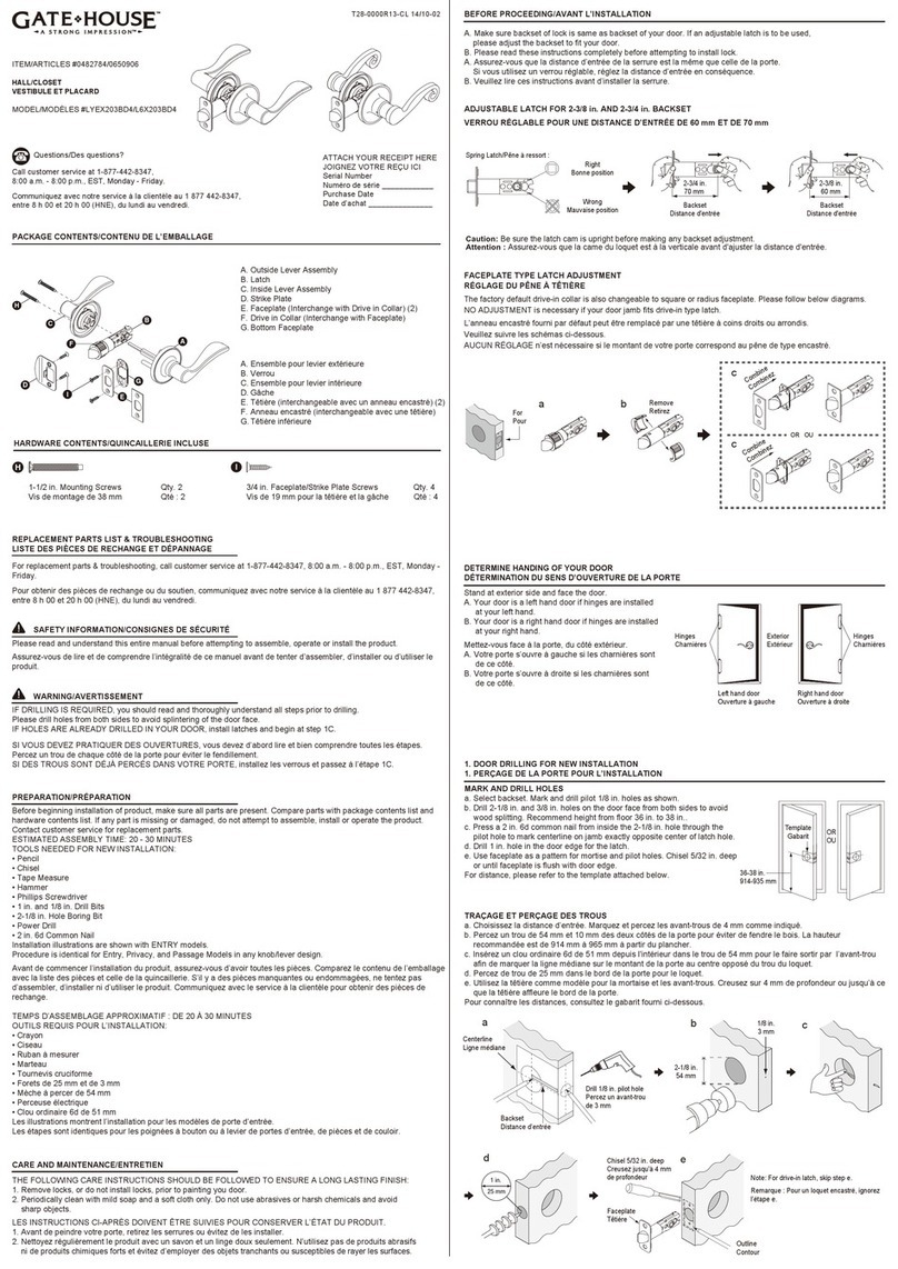
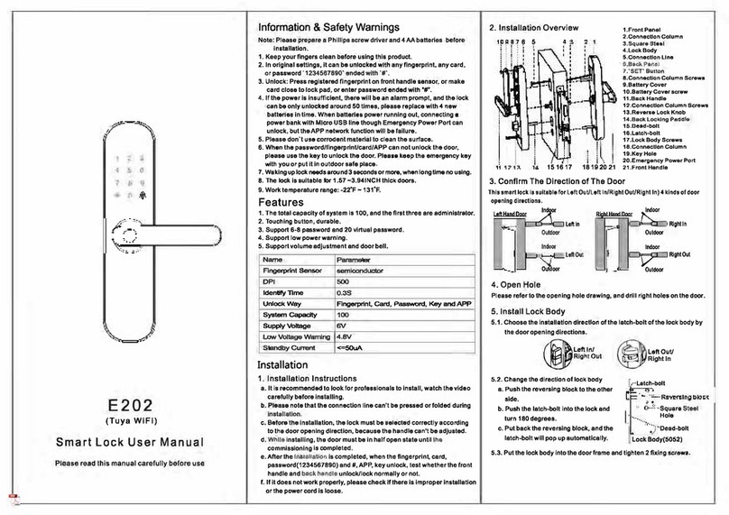
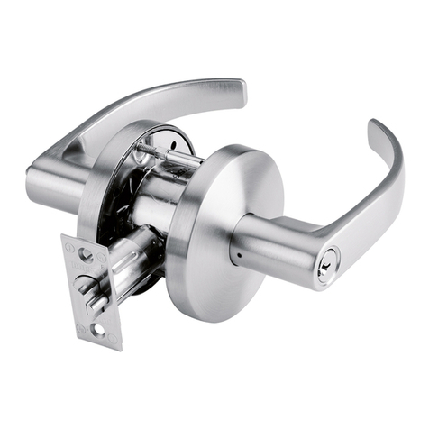
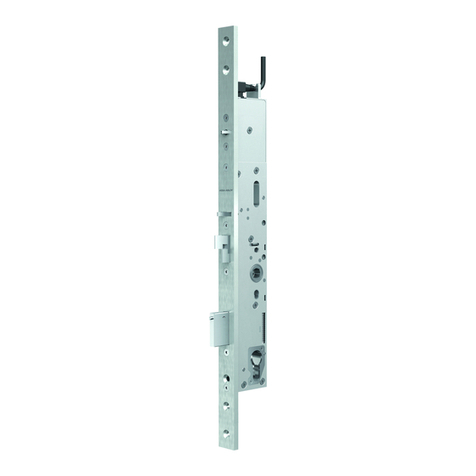
Gate House TUT30 User manual

Two (2) 1/8" (3mm) pilot holes
Faceplate
WARNING
IF DRILLING IS REQUIRED, you should read and thoroughly understand steps 1 - 4 prior to
drilling.
Please drill holes from both sides to avoid splintering of the door face.
IF HOLES ARE ALREADY DRILLED IN YOUR DOOR, install latches and begin at step 5.
For questions, please call 1-877-4GATEHS, 8:30 a.m. - 5:30 p.m. EST,
Monday through Friday.
SAFETY INFORMATION
INSTALLATION AND CARE NOTATIONS:
1. The important safeguards and instructions appearing in this manual are not meant to
cover all possible conditions and situations that may occur. It must be understood that
common sense, caution and care are factors which cannot be built into any product.
These factors must be supplied by the person(s) caring for and operating the unit.
PREPARATION
Additional tools needed for NEW installation:
• Pencil • Hammer • 2-1/8 in.(54mm) Hole Boring bit • Chisel • Power drill
• Tape measure • 1 in.(25mm) & 1/8 in.(3mm) Drill bits • 2 in.(51mm) 6d common nail
ITEM #0226069/0226087/0226090/0226091/0141055/0141053
0225974/0225976/0239863/0239857
BED & BATH/HALL & CLOSET
MODEL #TUT30/TUTG0/TUX230/TUX2G0/TUX730/TUX7G0
LY9X203/LY9X20G/LY9X703/LY9X70G
INSTRUCTIONS FOR INSTALLATION OF LOCKSETS
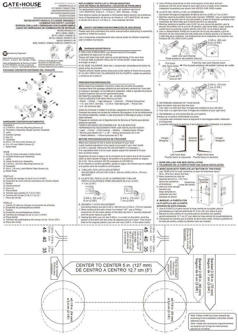
1. MARK DOOR
Use enclosed template to mark installation holes on both sides of the door as shown.
A. Heightline - 38 in. from floor (965mm).
B. Center of door thickness on heightline.
C. Knob hole center for backset - 2-3/8 in.(60mm) or 2-3/4 in.(70mm) as desired.
(Note 2-3/8 in.(60mm) is standard)
TO MARK OPPOSITE SIDE OF DOOR: fold template in opposite direction and place on other
edge of the door, matching up "mark (1B)" - center of door thickness as shown in
illustration.
(Back of template will be facing you.)
Mark knob hole center at point of template indentation (1C).
2. DRILL HOLES ( SEE ILLUSTRATIONS )
Drill 1/8 in.(3mm) pilot holes as marked in Step 1 at points (B) and (C).
A. Drill 2-1/8 in.(54mm) holes about 1/2 way through door, then finish drilling from other side,
to minimize splintering.
B. Before drilling latch holes, mark location for strike plate holes in door jamb by closing door
and inserting a 2 in.(51mm) common nail from inside 2-1/8 in.(54mm) hole in to pilot hole
so that nail makes an indentation in the jamb.
C. Open door and drill a 1 in.(25mm) latch hole in the door edge through to the 2-1/8 in.
(54mm) hole.
!
!
3. A. MORTISE FOR LATCH
Use faceplate as a pattern for mortise and pilot holes. Faceplate should fit flush.
B. lNSTALL LATCH
Install as shown. Ensure beveled edge faces door jamb.
4. PREPARE DOOR JAMB
Drill and Install strike plates
A. Mark outline for plastic dust box and then drill
33/64 in.(13mm) deep,
1-1/4 in. (32mm) height to allow for installation of plastic dust box,
61/64 in.(24mm) wide
Mark location of strike mortise using strike plate as a template by placing plate over
dust box and chisel outline. for strike plate with 1/8 in.(3mm) deep as marked on
door jamb
B. Insert dustbox into hole, and apply strikeplate.
Secure using 0.76 in.(19mm) wood screws into pilot holes as shown.
5. TUBULAR LOCK UNIVERSAL BACKSET LATCHBOLT
( This backset is set a 2-3/8 in.(60mm). It only needs to be adjusted if your door requires
a 2-3/4 in.(70mm) backset. )
IF BACKSET ADJUSTMENT IS NECESSARY:
A. Latch is preset at factory for 2-3/8 in.(60mm) backset.
Caution: Be sure the latch cam is upright before making any backset adjustment.
B. To convert latch to 2-3/4 in.(70mm) backset, pull the rear part until 2-3/4 in.(70mm) is
completely shown in indicator.
To correct cam expand to reset and compress back to 2-3/8 in.(60mm).
Note:
• Our latches come with interchageable faceplates, allowing conversion from a radius
shape toa square shape so it will fit most doors.
Look first at your door to determine which configuration will work best in your
application and make the suitable change according to the instructions below, if
needed.
• Converting from radius corner faceplate to square corner and vice versa:
Detach installed faceplate using a flat head screw driver.
Replace with new faceplate. Align holes in the faceplate and the base plate and snap
them together.
TCD-M0G0J12
09/12-02
A
B
C
38 in.(965mm) from finished floor
Template
Template
OR
2-1/8 in.
(54mm)
ABC
1 in.
(25mm)
}
(A1 )
B
A
}
0.76 in.(19mm)
(A1) Short wood screw
2-3/4 in.(70mm)
2-3/8 in.(60mm)
Yes No
Caution: Be sure the latch cam is upright before installing latch.
To correct, expand to 2-3/4 position to reset cam and compress back to 2-3/8 in.
Notch
Radius corner faceplate
Square corner faceplate
1-3/4 in.
(45mm)
1-3/8 in.
(35mm)
1-9/16 in.
(40mm)
Ø 2-1/8 in.(54mm)
Fold here. Place on
door edge.
Drill 1 in.(25mm)
hole at center of
door edge.
Backset 2-3/4 in.(70mm)
Backset 2-3/8 in.(60mm)
THE FOLLOWING CARE INSTRUCTIONS SHOULD BE
FOLLOWED TO INSURE A LONG LASTING FINISH:
1. Remove locks, or do not install locks, prior to painting you door.
2. Periodically clean with mild soap and a soft
cloth only.
Do not use abrasives or harsh chemicals, and
avoid sharp or scratching objects.

IF NEEDED, REVERSE LEVERS
Determine handing of your door
Stand on exterior side and face the door.
A. Your door is a left hand door if hinges are installed on the left side.
B. Your door is a right hand door if hinges are installed on the right side.
FOLLOW THE PROCEDURE BELOW FOR CHANGING LEVER HANDING:
The leverset is preset as a right hand lever. If your door is a right hand door, you can install it now. If your door is left hand door, you
can change the lever handing by following the procedure below:
1. Use allen wrench to loosen set screw attached to the lever.
2. Remove lever and install the lever of opposite handing.
3. Make sure to align set screw hole with the correspondng hole on the spindle.
4. Insert set screw and tighten with allen wrench to secure the assembly.
* Make sure that the handle portion of the lever extends toward the hinges of the door.
LIFETIME WARRANTY
The Manufacturer extends a Full Lifetime Mechanical and Finish Warranty to the original “User” of this Product against defects in materials
and workmanship as long as the User occupies the residential premises upon which the Product was originally installed.
Upon return of a defective Product to the Manufacturer, the Manufacturer shall either replace, repair or refund the purchase price in
exchange for the Product.
This warranty does not cover abused or misused Products or those Products used in commercial applications.
No other warranties, express or implied are made with respect to the Product including but not limited to any implied warranty of
merchantability or fitness for a particular purpose.
The Manufacturer DOES NOT authorize any person to create for it any obligation or liability in connection with the Product.
The Manufacturer maximum liability hereunder limited to the purchase price of the Product, in no event shall the company be liable for
any consequential, indirect, incidental or special damages of any nature arising from the sale or use of this Product, whether in contract,
tort, strict liability or otherwise.
( For warranty service, please call 1-877-4GATEHS, 8:30 a.m. - 5:30 p.m. EST, Monday through Friday )
Note: Should the Product be considered a consumer product it may be covered by the Magnusson Moss Federal Warranty Act, please be
advised that: (1) Some states do not allow limitations or incidental consequential damages on how long an implied warranty lasts so that
the above limitations may not bully apply: and (2) This warranty gives specific legal rights and a User may have other rights which may
vary from state to state.
REPLACEMENT PARTS LIST & TROUBLESHOOTING
For replacement parts & troubleshooting, please call service department at
1-877-4GATEHS, 8:30 a.m. - 5:30 p.m. EST, Monday through Friday.
Part Part #
Screw pack SCR-L784
Tubular Latch KLB710-AQA3PCD
INSTALLATION OF COMPLETE LEVER OR KNOB ASSEMBLY:
A. Install exterior lever or knob assembly, inserting square spindle with posts through latch.
B. Install the interior rose plate with the threaded hole of the connecting piece facing down. Push the rose plate against door face and
apply two mounting screws to tighten firmly.
C. Apply interior rose to cover the rose plate.
D. Apply interior knob or lever to engage with square spindle, pushing against interior rose and apply set screw to tighten to complete
assembly.
REMARKS :
A-1. Privacy lock ( Bed & Bath ) fits on doors requiring locking from inside such as bedroom and bathroom.
Press button ( push rod ) on the inside of the lock will lock the door. Locking will be automatically relieved by turning
inside knob or lever.
A-2. When the locking mechanism is engaged, you will need to insert a small pin or a pointed tool into the small hole
on the lower outside rose, and push it in to unlock the door.
B. Passage lock ( Hall & Closet ) fits on doors which do not require locking. Turning knob or lever on either side will
open the door.
1.4 in.(35.5mm)
0.2 in.(5mm)
0.76 in.(19mm)
Inside Outside
Square spindle
Connecting piece
Tubular latch
Rosette
Short wood screw
Set screws
Knob/lever reinforcement plate
Allen wrench
Interior knob/lever
Mounting screws
Using allen wrench to firmly tighten set screws.
Inside Outside
Outside
Locking relief tool
Outside emergency
unlocking access hole
A-2
Inside
Turning inside knob or
lever to relieve locking
Locking button
( push rod )
A-1
Locking Unlocking
A.
Hinges
Left hand door Right hand door
HingesExterior
B.
Outside Inside
Exterior lever and interior lever can be switched.
Spindle
Outside Inside
Printed in Taiwan
This manual suits for next models
19
Other Gate House Lock manuals
