Securitron Vista V2M1200 User manual

1
500-33705, Rev A
V2M1200/1290 Series Maglock
Installation Instructions
Securitron
Phoenix, AZ 85044
Tel: 1-800-624-5625
Mon-Fri: 6:00am - 4:00pm PDT
Fax: 1-800-232-7329
www.securitron.com

2
500-33705, Rev A
Table of Contents
Product Information................................................................................3
Electrical..............................................................................................3
Product Type.......................................................................................3
LED Operation Colors for V2M1200/1290 with MBS....................3
Recommended Tools.............................................................................3
Ensuring Correct Voltage Setting ........................................................4
Installing the V2M1200/1290 on an Out-Swinging Door..................4
Determining the Door Frame Header..............................................4
Installing the Armature Plate on a Solid Door................................5
Installing the Armature Plate on a Hollow Door.............................5
Installing the V2M1200/1290 on an In-Swinging Door.....................6
Wiring the V2M1200/1290 ....................................................................9
Electrical Specifications.....................................................................9
Typical Magnetic Lock Wiring...........................................................9
Wire Gauge Chart..............................................................................9
Magnetic Lock Care and Maintenance .............................................10
Troubleshooting....................................................................................10
VistaCare Warranty..............................................................................11

3
500-33705, Rev A
Product Information
Holding Force
1200 lbs (544 Kg)
Dimensions (L x W x H)
10-1/2” x 2-7/8” x 1-9/16” [266 mm x 72 mm x 40 mm]
Electrical
NOTE: Factory default setting is 24 VDC.
12 VDC and 24 VDC operation (field selectable via voltage selection
switch in the wiring compartment)
Product Type
NOTE 1: The V2M1200/1290 Series with Magnetic Bond Sensor
(MBS) uses a hall-effect sensor.
NOTE 2: The V2M1200/1290 Series with Door Position Switch (DPS)
uses a change-over reed switch sensor.
Besides the unmonitored version, the V2M1200/1290 Series Maglock is
available with either a MBS, a DPS, or both.
LED Operation Colors for V2M1200/1290 with MBS
The LED operation color can be set in the field. Colors can be reversed
by reversing the two-pin plug connection on the Printed Circuit Board
(PCB). The factory default setting is as follows:
LED indicator OFF No power to the magnet
LED indicator RED Power on magnet, door open
LED indicator GREEN Power on magnet, door closed
Recommended Tools
Screwdriver, #2 Phillips Center Punch
Drill Drill Bit: 15/32” [12 mm], 5/8”[16 mm],
Tap: ¼”-20 UNC [M6-1.0]

4
500-33705, Rev A
Ensuring Correct Voltage Setting
NOTE: Factory default setting is 24 VDC.
1. ENSURE the onboard PCB is set for the correct and desired
operating voltage.
2. IF a change is required,
THEN ACCESS the wiring compartment by removing the wiring
compartment Phillips head screw and cover (see
Figure 1, “Wiring Compartment”),
AND TOGGLE the 12V/24V slide switch to the desired position.
Figure 1. Wiring Compartment
3. REPLACE the cover and Phillips head screw.
Installing V2M1200/1290 on Out-Swinging Door
Determining the Door Frame Header
1. DETERMINE the type of door frame header and whether a filler
plate, header bracket, or angle bracket is required for installation
(see Figure 2, “Door Frame Installation Options”).
Figure 2. Door Frame Installation Options

5
500-33705, Rev A
2. REMOVE the header plate from the magnetic lock.
a. LOOSEN BUT DO NOT REMOVE the two Phillips head screws
on top of the header plate.
b. SLIDE and REMOVE the header plate from the magnetic lock.
3. FOLD the included installation template on the dotted line to form a
90-degree angle.
NOTE: If installing to a pair of double doors, the template is placed
at the center of the door opening.
4. PLACE the bottom portion of the installation template against the
door.
5. TAPE the installation template in place.
6. LOCATE and MARK the hole locations to the door and header
frame.
Installing the Armature Plate on a Solid Door
7. DRILL a 1/4” [6.35 mm] diameter hole through the armature side of
the door (see Figure 3, “Installing Armature to Solid Door”).
8. DRILL a 1/2” [12.7 mm] diameter hole into the door to accommodate
the armature bolt (see Figure 3).
Figure 3. Installing Armature to Solid Door
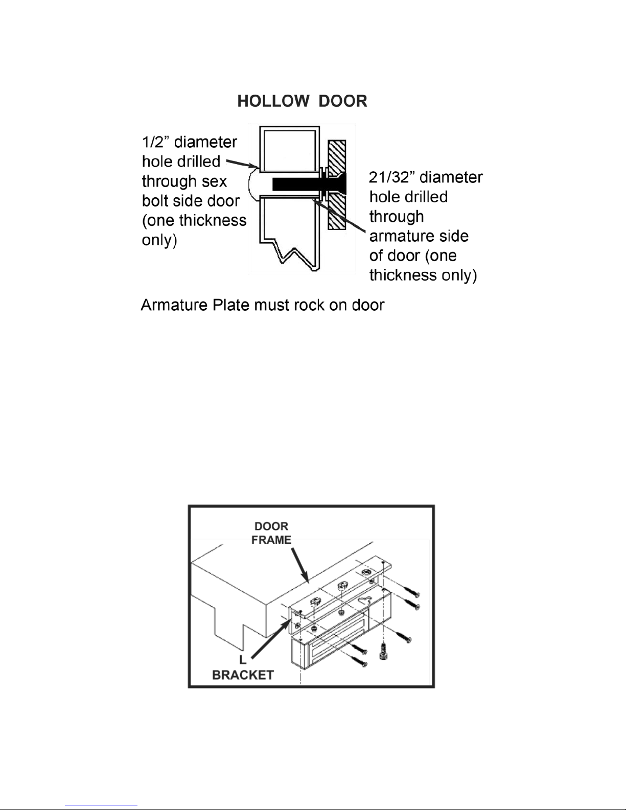
Installing the Armature Plate on a Hollow Door
9. DRILL a 21/32” [16.67 mm] diameter hole through the armature side
of the door (see Figure 4, “Installing Armature to Hollow Door”).
6
500-33705, Rev A
10. DRILL a 1/2” [12.7 mm] diameter hole through the sex bolt door side
to accommodate the armature bolt (see Figure 4).
Figure 3. Installing Armature to Solid Door
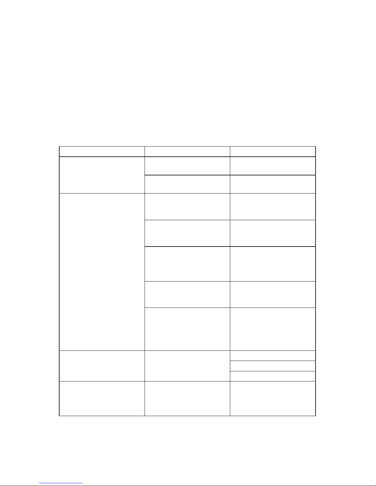
Installing V2M1200/1290 on In-Swinging Door
1. FASTEN the L bracket on the door frame in a suitable location.
2. MOUNT the magnetic lock to the L bracket.
3. ENSURE the magnetic lock does not obstruct the closing of the door.
4. CONNECT the correct voltage to the magnetic lock.

7
500-33705, Rev A
NOTE: The cap screws are not tightened at this time. The Z bracket
must be adjustable.
5. ASSEMBLE the Z bracket with the provided socket head cap screws.
NOTE: The rubber washer attached to the armature bolt is not
removed.
6. MOUNT the armature plate to the adjustable section of the Z bracket
using the armature bolt.
NOTE: The washer assembly must be between the armature plate and
the adjustable section of the Z bracket.
7. USE one rubber washer between the two metal washers on the
armature bolt.
NOTE: The armature must not be over tightened. The armature must
rock to align with the magnet.

8
500-33705, Rev A
8. CLOSE the door and ALIGN the armature plate to the magnet.
9. APPLY power to the magnet.
10. ALLOW the armature plate to bond with the magnet, ensuring the Z
bracket assembly is firmly against the closed door.
11. TIGHTEN the cap screws holding the Z bracket armature plate
assembly.
12. FASTEN the Z bracket assembly to the door using the supplied
screws.
13. ENERGIZE and DE-ENERGIZE the magnetic lock several times to
open and close the door in order to check the completed alignment
and installation of the magnet and armature plate.

9
500-33705, Rev A
Wiring the V2M1200/1290
Electrical Specifications
Single Magnetic Lock: 510 mA at 12 VDC
280 mA at 24 VDC
Double Magnetic Locks: 510 mA at 12 VDC (each lock)
280 mA at 24 VDC (each lock)
Typical Magnetic Lock Wiring
Wire Gauge Chart
D
C
C
u
r
r
e
n
t
Distance From Power Supply to Magnetic Lock
12 VDC
50
feet
100
feet
150
feet
200
feet
300
feet
400
feet
500
feet
750
feet
1000
feet
24 VDC
200 mA
24
22
22
22
20
18
18
16
14
24
24
24
22
22
22
20
20
18
300 mA
24
22
22
20
18
18
16
14
14
24
24
22
22
22
20
20
18
16
400 mA
22
22
20
18
18
16
14
14
12
24
22
22
22
20
18
18
16
14
600 mA
22
20
18
18
16
14
14
12
10
24
22
22
20
18
18
16
14
14
800 mA
22
18
18
16
14
12
10
10
8
22
22
20
18
18
16
14
14
12
1A
20
18
16
14
14
12
10
10
8
22
20
20
18
16
14
14
12
10
10
500-33705, Rev A
Magnetic Lock Care and Maintenance
Magnetic locks have no internal moving parts and require minimal
maintenance. It is recommended that the face of the armature place and
magnet be wiped clean and a light coating of a suitable silicone lubricant
applied to each surface to prevent rust, even though the mating surfaces
have been plated (required only if dirt buildup is observed. The armature
plate bolt and the Phillips head screws holding the magnet to the header
plate should be checked every three months to ensure a safe and secure
installation.
Troubleshooting
PROBLEM
CAUSE
SOLUTION
Lock Buzzes
AC voltage connected
to lock
SUPPLY DC voltage to
lock
AC ripple in power
supply
REPLACE power
supply
Insufficient Holding
Force
Incorrect input voltage
CHECK voltage switch
position for correct
setting
Low input voltage
CHECK power supply
voltage wire gauge
incorrect for wire run
Misalignment of
armature plate
CHECK to ensure
armature plate covers
all magnetic poles of
the lock
Armature plate screwed
tight to door
CHECK that armature
plate rocks on door to
align with door
Wrong hardware
assembly
CHECK that a metal
washer, rubber washer,
and metal washer are
between door and
armature plate
Door Does Not Lock
No power to door
CHECK power at lock
CHECK power supply
CHECK all connections
Door Status Sensor Not
Working (applicable
models)
Magnet in armature
plate not aligned with
lock
ALIGN magnet in
armature plate with door
status sensor dot on
lock
If any problem persists, call Technical Support at 1-800-624-5625 (toll free).

11
500-33705, Rev A
VistaCare Warranty
SECURITRON warrants that it will replace at customer’s request, for one
(1) year from the date of invoice, for any reason, products branded
VISTA by Securitron. SECURITRON will use its best efforts to ship a
replacement product by next day air freight at no cost to the customer
within 24 hours of SECURITRON’s receipt of the product from customer.
If the customer has an account with SECURITRON or a valid credit card,
the customer may order an advance replacement product, whereby
SECURITRON will charge the customer’s account for the price of the
product plus next day air freight, and will credit back to the customer the
full amount of the charge, including outbound freight, upon
SECURITRON’s receipt of the original product from the customer.
SECURITRON’s sole and exclusive liability, and customer’s sole
remedy, is limited to the replacement of the VISTA product when
delivered to SECURITRON’s facility (freight and insurance charges
prepaid by customer). The replacement, at SECURITRON’s sole option,
may be the identical item or a newer unit which serves as a functional
replacement. In the event that the product type has become obsolete in
SECURITRON’s product line, this VISTA warranty will not apply. This
VISTA warranty also does not apply to custom, built to order, or non-
catalog items, items made by others (such as batteries), returns for
payment, distributor stock reductions, returns seeking replacement with
anything other than the identical product, or products installed outside of
the United States or Canada. This VISTA warranty also does not apply to
removal or installation costs. SECURITRON will not be liable to the
purchaser, the customer or anyone else for incidental or consequential
damages arising from any defect in, or malfunction of, its products.
SECURITRON does not assume any responsibility for damage or injury
to person or property due to improper care, storage, handling, abuse,
misuse, or an act of God. EXCEPT AS STATED ABOVE, SECURITRON
MAKES NO WARRANTIES, EITHER EXPRESS OR IMPLIED, AS TO
ANY MATTER WHATSOEVER, INCLUDING WITHOUT LIMITATION
THE CONDITION OF ITS PRODUCTS, THEIR MERCHANTABILITY OR
FITNESS FOR ANY PARTICULAR PURPOSE.
For more information, visit www.securitron.com

12
500-33705, Rev A
Securitron is a brand associated with Hanchett Entry Systems, Inc., an ASSA
ABLOY Group company. Copyright © 2016, Hanchett Entry Systems, Inc.
All rights reserved. Reproduction in whole or in part without the express
written permission of Hanchett Entry Systems, Inc. is prohibited.
This manual suits for next models
1
Table of contents
Other Securitron Lock manuals


Popular Lock manuals by other brands


Viro
Viro WALL KEY COMBINATION BOX Installation and use manual

Schlage
Schlage L-SERIES Wiring Instructions and Specifications

Noark
Noark MIT26 installation instructions

Kwikset
Kwikset SMARTCODE 916 Installation and user guide

Schlage
Schlage ND50 installation instructions

ADI PRO
ADI PRO 0E-MAG600LB installation instructions


