manuals.online logo
Brands
  1. Home
  2. •
  3. Brands
  4. •
  5. Chamberlain
  6. •
  7. Garage Door Opener
  8. •
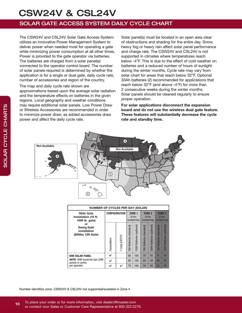
  9. Chamberlain LiftMaster CSW24V User manual

Chamberlain LiftMaster CSW24V User manual

1/4 gate length
1/4 gate length minus 14 inches
at least 9 inches
24 inches
28 inches
6 inches
(check local and
national codes)
QuickStartfor single gate applications
This QuickStart is intended to highlight a single right-hand gate application. Each application is unique and it is the responsibility of the purchaser, installer and end user to ensure that
the total gate system is installed and operated properly. Refer to the installation manual for complete information regarding installation, testing, and programming.
MODEL CSW24V
™
& CSW24VH
™
1 Install the concrete pad and conduit.
2 Attach the operator to the concrete pad.
3Position the operator arm onto the output shaft so that the pin slides
into the slot.
2
46
7
3
1
5
4 Concrete Anchors
1/2" x 3 1/2"
INSTALLATION
8
9
4 Position the gate bracket on the gate (1/4 the length of the gate
from the gate hinge center). Ensure the arm is level.
5 Weld the gate bracket and long arm section in this position.
6 Weld the short arm section.
7 Secure the operator arm to the output shaft.
8 Tighten the handle.
9 Remove the pin from the vent plug on both the top and bottom
gear boxes.
INSTALL THE COVER
1Remove the operator arm from the output shaft by
releasing the handle.
2Align the tabs on the rear cover with the slots on the chassis
and place the cover over the operator.
3Secure both sides of the rear cover to the chassis with two
5/16-18 hex bolts and washers.
4Reattach the operator arm to the output shaft (making sure
the pin fits into the slot) and secure by pushing the handle
down.
5Place the operator arm cover over the operator arm and
secure.
6Align the front cover with the back cover, making sure the
grooves line up.
7Secure the front cover to the chassis with two 5/16-18 hex
bolts and washers.
8Secure the front cover to the rear cover using the 5/16-18
screw.
Tabs on Rear Cover
Slots on Chassis
Groove on Front Cover
5/16-18
Hex Bolts
and Washers
5/16-18
Screw
ALARM
RESET
+
DC
+ -
BATT
©2011 The Chamberlain Group, Inc.
01-35589 All Rights Reserved
WIRING
FINE TUNE THE FORCE
PROGRAMMING
INITIAL LIMITS AND FORCE ADJUSTMENT
OBSTRUCTION TEST
When limits are set properly the operator will automatically exit limit setting mode.
51Press and release the SET OPEN and SET CLOSE buttons simultaneously to enter limit setting mode.
2Press and hold one of the MOVE GATE buttons to move the gate to the
open or close limit.
3Press and release the SET CLOSE or SET OPEN button
depending on which limit is being set.
4Press and hold one of the MOVE GATE button to move the
gate to the other limit.
5Press and release the SET CLOSE or SET OPEN button depending on which
limit is being set.
61Open and close the gate with the test buttons.
2If the gate stops or reverses before reaching the fully open or
closed position, increase the force by turning the force control
slightly clockwise.
7
81Press and release the LEARN
button (operator will beep
and green XMITTER LED will
light).
2Press the remote control button for the
desired function. The
operator will automatically
exit learn mode (operator
will beep and green
XMITTER LED will go out)
if programming is
successful.
6Cycle the gate open and close. This automatically sets the force.
The FORCE DIAL on the control board is used for fine tuning the force. The force setting should be high enough that
the gate will not reverse by itself nor cause nuisance interruptions, but low enough to prevent serious injury to a
person. The force setting is the same for both the open and close gate directions.
3Perform the “Obstruction Test” after every force setting adjustment (see below).
1Open and close the gate with the test buttons, ensuring that the gate is stopping at the proper open and close limit
positions.
2Place a solid object between the open gate and a rigid structure. Ensure that the gate, the solid object, and the rigid
structure can withstand the forces generated during this obstruction test.
3Run the gate in the close direction. The gate should stop and reverse upon contact with the solid object. If the gate
does not reverse off the solid object, reduce the force setting by turning the force control slightly counter-clockwise.
The gate should have enough force to reach both the open and close limits, but MUST reverse after contact with a
solid object.
4Repeat the test for the open direction.
To protect against fire and electrocution:
• DISCONNECT power and battery BEFORE
installing or servicing operator.
For continued protection against fire:
• Replace ONLY with fuse of same type and
rating.
WIRE THE ENTRAPMENT PROTECTION DEVICES
Connect the entrapment protection device to the EYES EDGE terminal on the control
board.
• Close Photoelectric Sensor Entrapment Protection: Connect wires from the
photoelectric sensors to the Inputs on the CLOSE EYES/INTERRUPT terminal.
• Close Edge Entrapment Protection: Connect wires from the entrapment protection
device to the Inputs on the CLOSE EDGE terminal.
• Open Entrapment Protection: Connect wires from the entrapment protection device
to the Inputs on the OPEN EYES/EDGE terminal.
POWER WIRING
This operator can be wired for either 120 Vac or 240 Vac or a
solar panel (not provided). These instructions show a 120 Vac
application. For information regarding a 240 Vac or solar
application refer to the installation manual.
1
2EARTH GROUND ROD
1Install the earth ground rod within 3 feet
of the operator.
2Run wire from the earth ground rod to the
operator.
Check national and local
codes for proper depth
3
4CONNECT BATTERIES
Red Wire
Black Wire
Jumper
1Connect the battery wires to the
J15 plug on the control board.
2Turn ON AC power to the
operator.
3Turn ON the AC power switch on
the operator.
1Turn off the AC power from the main
power source circuit breaker.
2Run the AC power wires to the
operator.
3Connect the green wire to the earth
ground rod and AC ground using a
wire nut. NOTE: The earth ground
rod can be grounded to the chassis.
4Connect the white wire to NEUTRAL
using a wire nut.
5Connect the black wire to HOT using
a wire nut.
Junction Box
SET OPEN SET CLOSE
OFF
PRESS &
RELEASE
TO BEGIN
LIMIT
ALARM
RESET
MOVE
GATE
5
INPUT POWER
STATUS:
PRESS &
RELEASE
TO BEGIN
SETUP
LIMIT
TO BEGIN
LIMIT
PRESS &
RELEASE
TO BEGIN
ALARM
RESET
60
180 MIN MAX
BATT LOW
NETWORK
OPEN CLOSE STOP
XMITTER
NETWORK
AC Power Switch
Other manuals for LiftMaster CSW24V

1

This manual suits for next models

1

Other Chamberlain Garage Door Opener manuals

Chamberlain Security+ 1215EM FS2 User manual

Chamberlain

Chamberlain Security+ 1215EM FS2 User manual

Chamberlain PRO7100 User manual

Chamberlain

Chamberlain PRO7100 User manual

Chamberlain LiftMaster Professional 50-1950 User manual

Chamberlain

Chamberlain LiftMaster Professional 50-1950 User manual

Chamberlain T User manual

Chamberlain

Chamberlain T User manual

Chamberlain 050ACTWFLK Use and care manual

Chamberlain

Chamberlain 050ACTWFLK Use and care manual

Chamberlain POWER DRIVE 248735S 3/4 HP User manual

Chamberlain

Chamberlain POWER DRIVE 248735S 3/4 HP User manual

Chamberlain MotorLift ML750 User manual

Chamberlain

Chamberlain MotorLift ML750 User manual

Chamberlain Infinity B User manual

Chamberlain

Chamberlain Infinity B User manual

Chamberlain Security+ 4640 User manual

Chamberlain

Chamberlain Security+ 4640 User manual

Chamberlain CSW200UL8 User manual

Chamberlain

Chamberlain CSW200UL8 User manual

Chamberlain MotorLift 1703EML User manual

Chamberlain

Chamberlain MotorLift 1703EML User manual

Chamberlain 3585-100 3/4 HP User manual

Chamberlain

Chamberlain 3585-100 3/4 HP User manual

Chamberlain Whisper Drive Security+ 182671D User manual

Chamberlain

Chamberlain Whisper Drive Security+ 182671D User manual

Chamberlain 1345 - 1HP User manual

Chamberlain

Chamberlain 1345 - 1HP User manual

Chamberlain Security+ 6200-2K User manual

Chamberlain

Chamberlain Security+ 6200-2K User manual

Chamberlain 3280 1/2 HP User manual

Chamberlain

Chamberlain 3280 1/2 HP User manual

Chamberlain LiftMaster 50-WSE-14 User manual

Chamberlain

Chamberlain LiftMaster 50-WSE-14 User manual

Chamberlain GH User manual

Chamberlain

Chamberlain GH User manual

Chamberlain Security+ HD200D User manual

Chamberlain

Chamberlain Security+ HD200D User manual

Chamberlain LiftMaster 355LM Security+ User manual

Chamberlain

Chamberlain LiftMaster 355LM Security+ User manual

Chamberlain Series 1000E User manual

Chamberlain

Chamberlain Series 1000E User manual

Chamberlain PRO8000 User manual

Chamberlain

Chamberlain PRO8000 User manual

Chamberlain 2110 1/3 HP User manual

Chamberlain

Chamberlain 2110 1/3 HP User manual

Chamberlain 2580 1/2 HP User manual

Chamberlain

Chamberlain 2580 1/2 HP User manual

Popular Garage Door Opener manuals by other brands

Connect SmartHome CSH-GRGDROPN user manual

Connect SmartHome

Connect SmartHome CSH-GRGDROPN user manual

DIGIWAY PTY SL1000 instruction manual

DIGIWAY PTY

DIGIWAY PTY SL1000 instruction manual

Accessmatic Scorpion 901 user manual

Accessmatic

Accessmatic Scorpion 901 user manual

DITEC TS35 Technical manual

DITEC

DITEC TS35 Technical manual

Wayne-Dalton Flush 42 quick start guide

Wayne-Dalton

Wayne-Dalton Flush 42 quick start guide

Linear LDC0800 user guide

Linear

Linear LDC0800 user guide

Wayne-Dalton 9100 installation manual

Wayne-Dalton

Wayne-Dalton 9100 installation manual

Motostar S500R installation manual

Motostar

Motostar S500R installation manual

Craftsman 139.53930DM owner's manual

Craftsman

Craftsman 139.53930DM owner's manual

King gates Couper 24 instruction manual

King gates

King gates Couper 24 instruction manual

Raynor 1280RGD owner's manual

Raynor

Raynor 1280RGD owner's manual

Stratco SDO800G installation guide

Stratco

Stratco SDO800G installation guide

Multi-code 1090 installation instructions

Multi-code

Multi-code 1090 installation instructions

SOMFY Dexxo Pro io installation manual

SOMFY

SOMFY Dexxo Pro io installation manual

Dieffematic TXR-P8 quick start guide

Dieffematic

Dieffematic TXR-P8 quick start guide

Craftsman 139.18571D owner's manual

Craftsman

Craftsman 139.18571D owner's manual

Meross MSG100 Voice Commands Guide

Meross

Meross MSG100 Voice Commands Guide

Genie GCL NEMA 4 Installation supplement

Genie

Genie GCL NEMA 4 Installation supplement

manuals.online logo
manuals.online logoBrands
  • About & Mission
  • Contact us
  • Privacy Policy
  • Terms and Conditions

Copyright 2025 Manuals.Online. All Rights Reserved.