Thiele TWN 0861 User manual

MOUNTING INSTRUCTIONS
CHAIN COUPLING SHACKLES
GRADES 80 AND 100
THIELE GmbH & Co. KG # change indicator
www.thiele.de | info@thiele.de B11 91-B replaces B11 91-A
© All rights reserved US 3.2 22 1 | 5
Clevis chain
coupling shackles
TWN 0861
Clevis chain coupling
bolt shackles
TWN 0862
Clevis special
shackles
TWN 0897
The following mounting inst uctions must always be
followed to avoid the isk of pe sonal inju y o p ope ty
damage.
Do not use a chain coupling shackles befo e eading these
mounting inst uctions.
1. ABOUT THIS INSTRUCTION
These mounting instructions describe in particular how chain
coupling shackles according to TWN 861, TWN 862 and
TWN 897 (TWN = THIELE works standard) are to be safely
used for lifting purposes.
The instructions apply analogously to components of identical
design.
To comply with these mounting instructions is essential to help
avoid hazards and increases the reliability and service life of
the chain coupling shackles.
DANGER! Indicates a hazardous
situation, which, if not avoided, will
result in death or serious injury.
WARNING! Indicates a hazardous
situation, which, if not avoided, could
result in death or serious injury.
CAUTION! Indicates a hazardous
situation, which, if not avoided, could
result in minor or moderate injury.
NOTICE! Is used to address practices not
related to physical injury.
SAFETY INSTRUCTIONS signs indicate
specific safety-related instructions or
procedures.
Chains and accesso ies ma ked with the Ame ican nominal
size 7/32” al eady co esponded to Eu opean nominal size
6 mm. In o de to achieve a bette match, the p evious
nominal size 7/32" is now conve ted to the new nominal size
1/4”
#
. The wo king load limits have now also been adjusted.
#
DEFINITIONS
Clevis
A U-shaped fitting with pin.
Working Load Limit (WLL)
The maximum load which a chain coupling shackle is designed
to support.
Read ASME B30.26 “Rigging Ha dwa e”,
Chapte s 26-0, 26-1, 26-4.
2. BASIC SAFETY REQUIREMENTS
To p event the isk of inju y neve walk o stay unde lifted
loads!
The wo king load limit must not be exceeded!
Chain coupling shackles as well as lifting and attachment
means to be used must be f ee f om defects!
Wo king unde the influence of d ugs, medications
impai ing the sense and/o alcohol is st ictly fo bidden!
•Operators, fitters and maintenance personnel must in
particular observe the operating and mounting instructions
as well as standards ASTM A 9 6/A 9 6 M (Standard
Specification for Grade 8 and Grade 1 Alloy Steel Chain
Slings for Overhead Lifting), ASTM A 952/A 952 M (Standard
Specification for Forged Grade 8 and Grade 1 Steel
Lifting Components and Welded Attachment Links),
ISO 56 (Non-calibrated round steel link lifting chain and
chain slings; Use and maintenance), ISO 7593 (Chain slings
assembled by methods other than welding; Grade T(8)) and
ISO 4778 (Round steel short link chains for lifting purposes –
Chains slings of welded construction – Grade 8).
•The specific safety and operating regulations and standards
issued locally in the country where the items are used must
be observed.
•The directions given in these mounting instructions and
specified documentations relating to safety, assembly,
operation, inspection, and maintenance must be made
available to persons operating and using the chain coupling
shackles.
MOUNTING INSTRUCTIONS
CHAIN COUPLING SHACKLES
GRADES 80 AND 100
THIELE GmbH & Co. KG # change indicator
www.thiele.de | info@thiele.de B11 91-B replaces B11 91-A
© All rights reserved US 3.2 22 2 | 5
•These mounting instructions must be available in a place
near the product during the time the equipment is used.
Please contact the manufacturer if replacements are
needed. See also chapter 11.
•During operation work, wear your personal protective
equipment!
•Imp ope assembly and use may cause pe sonal inju y
and/o damage to p ope ty.
•Assembly and removal as well as inspection and
maintenance must exclusively be carried out by skilled and
authorized persons.
•Structural changes are impermissible (e.g. welding,
bending).
•Never attempt to make the shackle opening smaller by
bending or welding in intermediate elements.
•Ope ato s must ca y out a visual inspection and, if
necessa y, a functional test of the safety equipment
befo e each use.
•Usage without safety devices (nuts, dowels pins) is not
permitted.
•Never put to use worn-out, bent or damaged shackles.
•Never expose shackles to loads exceeding the specified
working load limits.
•Do not use force when mounting/positioning shackles.
•Make sure the load can take the forces to be applied
without suffering deformation.
•Lateral loads bending the shackles are not permissible.
Shackles must be capable of aligning themselves in loading
direction.
•Do not start lifting before you have made sure the load has
been correctly attached.
•No one including you (ope ato ) must be in the way of the
moving load (haza d a ea).
•During lifting make sure your hands or other body parts do
not come into contact with lifting means. Only remove
lifting means manually (use your hands).
•Avoid impacts, e.g. due to abruptly lifting loads with lifting
means in slack condition.
•Applications where the bolt may become threaded out, e.g.
by a rope or load, shall be avoided. If such applications
cannot be avoided bolts with safety pins shall be used.
•If shackles are expected to perform under continuous
service conditions (multi-shift, automatic operations or the
like) contact the manufacturer first to reduce the working
load limit as necessary.
•Never move a suspended load over persons.
•Never cause suspended loads to swing.
•Always monitor a suspended load.
•Put the load only down in flat places/sites where it can be
safely deposited.
•Avoid shackles to get caught under the load.
•In the event of doubts or concerns about the proper and
safe use, inspection, maintenance or similar things contact
your safety officer or the manufacturer.
THIELE is not esponsible fo damage caused by non-
obse vance of the inst uctions, ules, standa ds and notes
indicated!
As a ule, chain coupling shackles a e not pe mitted fo the
t anspo tation of pe sons.
3. DESCRIPTION AND INTENDED USE
THIELE Chain coupling shackles are intended as end fittings of
chain sling assemblies. The chain strands are to be fitted
directly to the clevis. Shackles of TWN 861 are intended to be
mounted once to be left on the load permanently.
Shackles must only be used
•within the limits of their permissible working load limit,
•for permissible attachment methods and sling angles,
•within the temperature limits prescribed,
•with their original bolts and dowel pins of appropriate size,
•by trained and authorized persons.
Failure to do so may cause serious injury or property damage.
THIELE-Chain coupling shackles meet EG Machinery Directive
2 6/42/EG requirements and feature a safety factor of at
least 4 based on working load limit (WLL).
THIELE shackles are designed to withstand 2 dynamic load
changes under maximum load conditions. In the event of
higher loads (e.g. multi-shift/automatic operation, magnetic
spreaders) the working load limit must be reduced.
Generally, they are marked with the associated chain size and
grade, manufacturer’s symbol and traceability code.
Shackles must only be used with a single loaded chain leg.
Shackles can also be used within lashing chain assemblies.
When used within a lashing system the maximum lashing
capacity (LC) is obtained by doubling the working load limit.
Any alternating use for lifting and lashing purposes is
impermissible!

MOUNTING INSTRUCTIONS
CHAIN COUPLING SHACKLES
GRADES 80 AND 100
THIELE GmbH & Co. KG # change indicator
www.thiele.de | info@thiele.de B11 91-B replaces B11 91-A
© All rights reserved US 3.2 22 3 | 5
4. COMMISSIONING
Prior to using the components for the first time assure that
•the shackles comply with the order and have not been
damaged,
•test certificates and mounting instructions are at hand,
•markings correspond with what is specified in the
documentation,
•inspection deadlines and the qualified persons for
examinations are determined,
•visibility and functional testings are carried out and
documented,
•documentation is safely kept in an orderly manner.
Dispose of the packing in an environmentally compatible way
according to local rules.
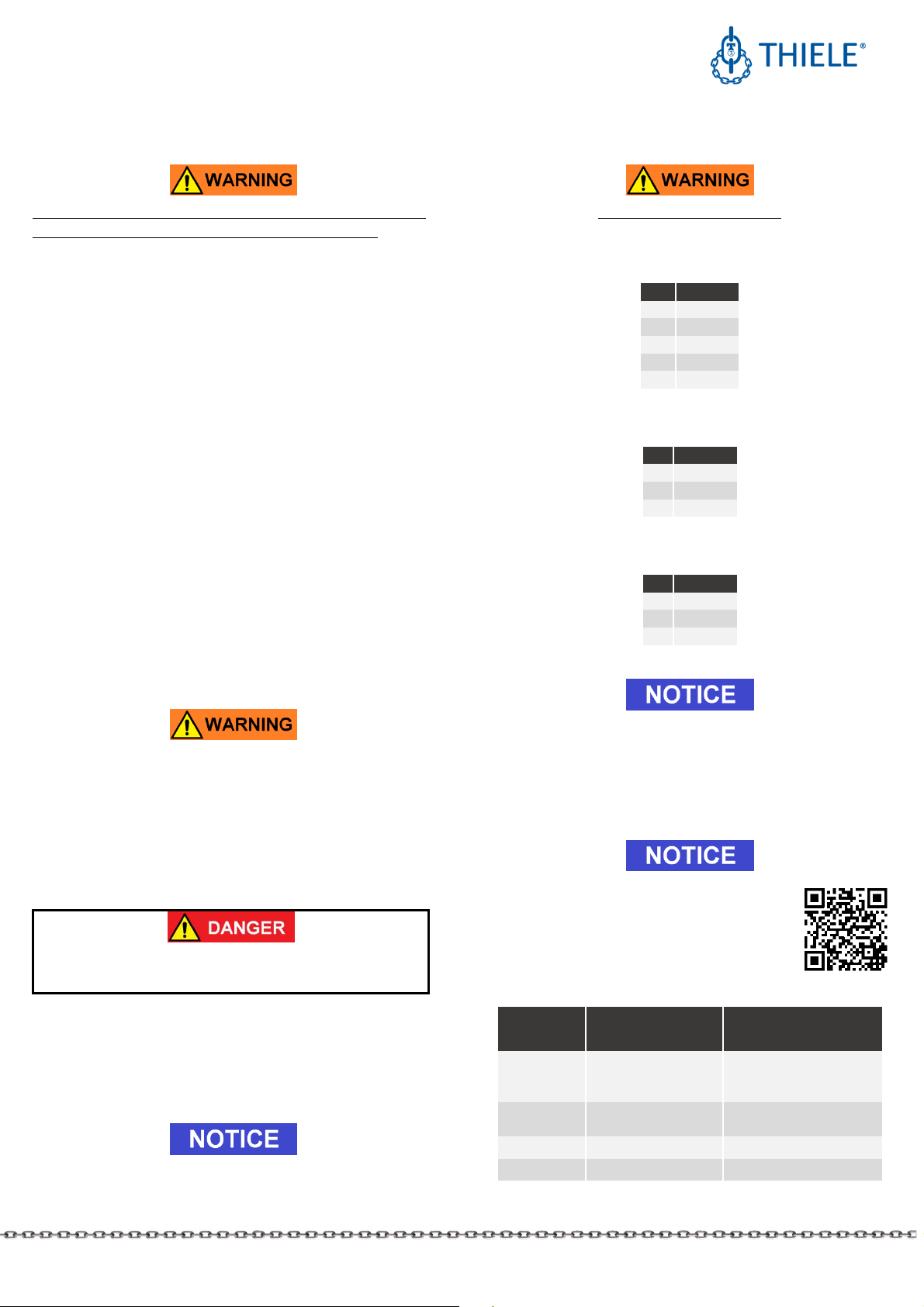
5. TECHNICAL DATA
Tables include only article numbers of standard and not
customized parts.
5.1 Specia chain coup ing shack es, TWN 0861,
Grade 80
Nominal
size A ticle no.
WLL
[lbs]
Dimensions [mm]
Mass
[lbs]
E D
C
F B
1
B
2
3/8 F3 6 1 7 1 64 16 32 36 21 47 1.34
1/2 F3 611 12 83 2 4 49 27 61 2.73
5/8 F3 621 18 1 99 24 48 56 33 75 4.63
5.2 Chain coup ing shack es, TWN 0862, Grade 80
Nominal
size A ticle no.
WLL
[lbs]
Dimensions [mm] Mass
[lbs]
E D
C
F B
1
B
2
3/8 F3 6 7 1 64 16 32 36 21 47 1.48
1/2 F3 61 12 83 2 4 49 27 61 3. 2
5/8 F3 62 18 1 99 24 48 56 33 75 5. 3
5.3 Specia coup ing shack es, TWN 0897,
Grade 80
Nominal
size A ticle no.
WLL
[lbs]
Dimensions [mm] Mass
[lbs]
E D
C
F B
1
B
2
1/4
#
F3 586 2 5 7 2 39 46 35 65 1. 4
5/16 F3 596 4 5 7 2 39 46 35 65 1.19
6. ASSEMBLY AND REMOVAL
6.1 Genera
All components to be installed or used must be in perfect
condition and the relevant Working Load Limits of all parts
must accommodate the respective load to be handled.
Allways assemble/remove shackles or parts in load-free
condition.
To prevent unilateral loads and misalignment spacers may be
arranged to center the load application point on the bolt.
Disassemble the parts in reverse order.
Use a suitable drift punch to drive the dowel pins out.
Suitable drift punches are available by article no. Z 33 3.
Dowel pins and cotter pins must only be installed once.
6.2 C evis fastening system
The clevis fastening system only
permits attachment of the nominal
chain size that suits the attachment
component.
6.2.1 ASSEMBLY
•If necessary, remove dowel pin
and pin.
•(A) Place end of chain leg
between the lateral clevis
elements.
•(B) Push pin from the side fully
into the clevis and through the last chain link of the leg.
•(C) Drive dowel pin fully in (must not project) to secure the
pin. The slot must face away from the pin.
Check whether the chain runs smoothly.
The dowel pins must only be installed once.

MOUNTING INSTRUCTIONS
CHAIN COUPLING SHACKLES
GRADES 80 AND 100
THIELE GmbH & Co. KG # change indicator
www.thiele.de | info@thiele.de B11 91-B replaces B11 91-A
© All rights reserved US 3.2 22 4 | 5
Only connect pins and attachment components of identical
grades. Starting with Ø ½” the pins are marked on the front
end.
6.2.2 DISASSEMBLY
•Slacken the respective chain leg.
•(A) Drive dowel pin out using
hammer and drift punch
1)
.
•(B) Push pin out using a drift
punch.
•(C) Remove the chain.
Suitable drift punches are available by article no. Z 33 3.
6.3 Bo t assemb y TWN 0861
A) Move the bolt (1) through both
holes in the shackle ends and see
to it that the two grooves in the
bolt are positioned concentrically
with the dowel pin holes in the
shackle body.
B) Insert the dowel pins (2). Make
sure the slot faces away from the
bolt towards the shackle bow.
6.4 Bo t assemb y TWN 0862 and TWN 0897
A) Fully insert the bolt (1) through both
shackle boreholes.
B) Retain the bolt with a suitable nut
(2) and tighten the nut so as to be
hand-tight using an appropriate tool.
Make sure bolt and nut are evenly
seated against the shackle body.
C) Finally, insert the cotter pin (3) in
the respective hole in the bolt
to secure the connection.
7. CONDITIONS OF USE
7.1 Norma use
Shackles must not be exposed to bending loads; make sure
eccentric loads are avoided.
Shackles must be able to move freely. Supporting of shackles
on other parts is not permitted.
Take care that
•incorrect arrangements are avoided, e.g. eccentric loads,
•damage of lifting or lashing accessories, e.g. by sharp edges,
is not possible,
•the shackles can be reached easily for fitting/unhinging
lifting or lashing accessories.
wrong correct correct
7.2 Inf uence of temperature
The respective temperature range limits must be considered
for all components used.
Using chain coupling shackles in high temperatures will cause
the working load limit to be reduced as indicated below.
Tempe atu e ange Remaining WLL
-4 °C ≤ t ≤ 2 5 °C
-4 °F ≤ t ≤ 4 °F 1 %
2 5 °C < t ≤ 3 °C
4 °F < t ≤ 572 °F 9 %
3 °C < t ≤ 4 °C
572 °F < t ≤ 752 °F 75 %
If a shackle has been exposed to tempe atu es exceeding
the maximum values specified, it must not be used
fu the mo e.
7.3 Environmenta inf uence
Chain Coupling Shackles must not be used in environments
where acids, aggressive or corrosive chemicals or their fumes
are present.
Hot-dip galvanizing or a galvanic treatment is prohibited as
well. Chain coupling shackles are not intended for applications
in abrasive blasting environments.
7.4 Especia y hazardous conditions
The degree of danger when used for the lifting of hazardous
loads, such as for example liquid metal or similar, risk
potentials must be assessed by a competent person in the form
of a risk analysis. Any additional rules and directives must be
followed in this case.
MOUNTING INSTRUCTIONS
CHAIN COUPLING SHACKLES
GRADES 80 AND 100
THIELE GmbH & Co. KG # change indicator
www.thiele.de | info@thiele.de B11 91-B replaces B11 91-A
© All rights reserved US 3.2 22 5 | 5
8. INSPECTION, MAINTENANCE, DISPOSAL
Inspections and maintenance must be arranged by the owner!
Inspection intervals shall be determined by the owner!
Visual inspections must be regularly carried out and
documented by competent and trained persons, at least once a
year or more frequently if the shackles are in heavy duty
service. After three years at the latest they must additionally
be examined for cracks. A load test is not a substitute for this
examination.
The results of the inspection shall be kept in a file that has to
be set up for each shackle before first used. The register will
show characteristic data of the shackles as well as identity
details.
Immediately stop using chain coupling shackles that show the
following defects:
•missing or illegible identification/marking,
•deformation, elongation or fractures,
•cuts, notches, cracks, incipient cracks, pinching,
•damaged threads,
•heating beyond permissible limit,
•severe corrosion,
•impaired or missing safety systems,
•wear in excess of 1 %, e.g. in the receiving area of the pin
diameter,
•missing or damaged pin locks or removal preventing guards.
Cleaning (e.g. prior to inspections) must not take place by using
flames or methods that might cause hydrogen embrittlement
(e.g. pickling or immersion in acidic solutions).
8.1 Inspection service
THIELE offers inspection, maintenance and repair services by
trained and competent personnel.
8.2 Maintenance
Maintenance and epai wo k must only be pe fo med by
competent and t ained pe sons.
Minor notches and cracks may be eliminated by careful
grinding observing the maximum cross section reduction
requirement of 1 % and avoid making more severe cuts or
scores. All maintenance and repair activities must be
documented properly.
8.3 Disposa
All components and accessories of steel taken out of service
must be scrapped in accordance with local regulations and
provisions.
9. SPARE PARTS
Use only original spare parts.
9.1 Spare part sets for c evis fastening system
Sets consist of pin and dowel pin.
Size A ticle no.
1/4
#
F48694
5/16
F48352
3/8 F48355
1/2 F48358
5/8 F48361
9.2 Pin sets for TWN 0861
Sets consist of pin and dowel pins.
Size
A ticle no.
3/8
F48 36
1/2
F48 39
5/8
F48 42
9.3 Pin sets for TWN 0862
Sets consist of pin, nut and cotter pin.
Size
A ticle no.
3/8
F3 451
1/2
F3 461
5/8
F3 471
1 . STORAGE
Shackles must be stored properly sorted and in dry conditions
at temperatures between 32 °F and 1 4 °F.
Do not store in a manner that cause mechanical damage.
11. THIELE OPERATING AND MOUNTING
INSTRUCTIONS
Current mounting and operating instructions
are available as a PDF download on the THIELE-
website www.thiele.de.
12. PUBLISHING INFORMATION
#
Company KWS Inc. THIELE GmbH & Co. KG
(Distributor) (Manufacturer)
Postal
address
P.O. Box 47 487
Tulsa, OK 74147
USA
Werkstrasse 3
5864 Iserlohn
Germany
Phone
number +1 (539) 367 2274 +49 2371/947-
Fax number +1 (539) 367 2278 +49 2371/947-241
This manual suits for next models
10
Table of contents
Other Thiele Lifting System manuals


Popular Lifting System manuals by other brands


Harbor Freight Tools
Harbor Freight Tools PITTSBURGH 56617 Owner's manual & safety instructions

morse
morse 400A-72-115 Operator's manual

Wabtec
Wabtec Ricon S Series Service manual

Phoenix Mecano
Phoenix Mecano Rose+Krieger RKPowerlift M Memory Assembly instructions

probst
probst EL-SDH operating instructions

Molift
Molift Rail System Handbook


