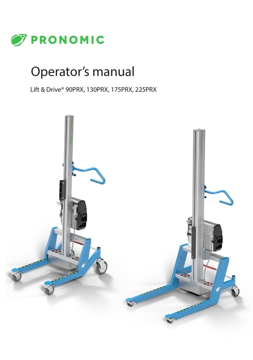
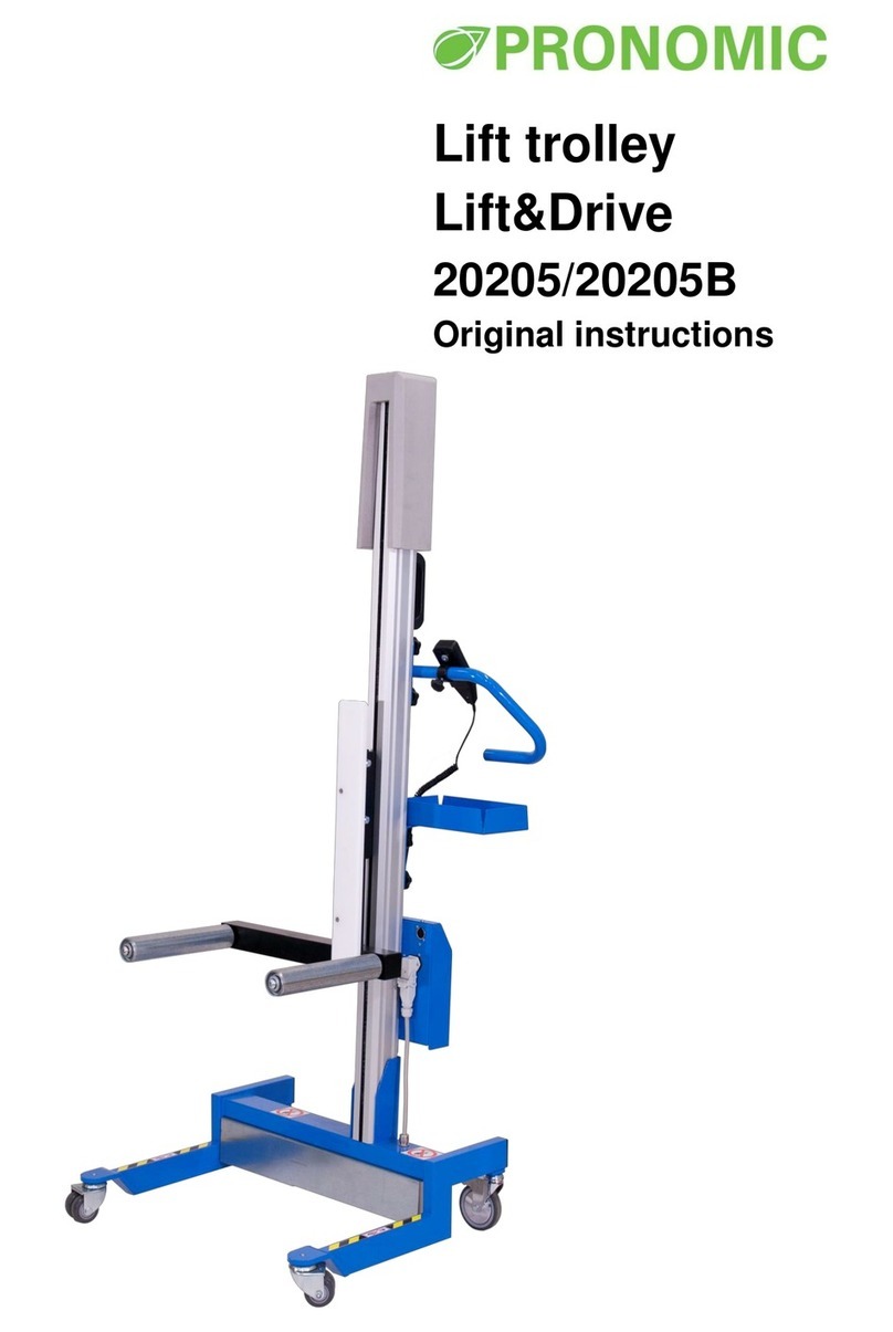
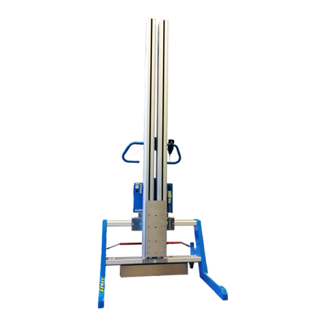
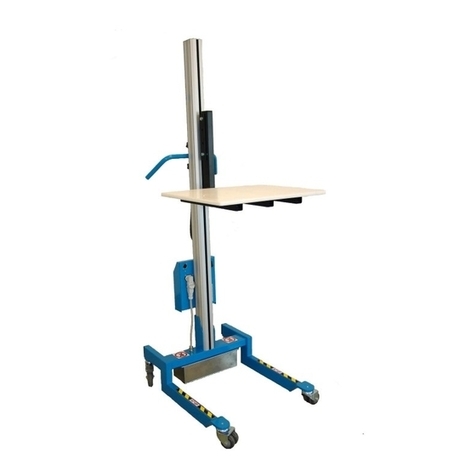
Pronomic 90P User manual

Parts for Stationary
lifter
(90P/125P130P/175P/
225P)
Original instructions

It is important that you read and understand the manual before assembly.
Do you have any questions? –Please contact the distributor or the manufacturer.
Pronomic AB
Visiting address:
Domherrevägen 15
192 55 Sollentuna
Sweden
Postal address:
Box 5504
192 05 Sollentuna
Sweden
Phone: +46 8-544 706 60
Fax: +46 8-544 706 70
E-mail: info@pronomic.se
www.pronomic.se
R150415

Contents
1Description of the parts......................................................................................................1
1.1 Warranty...................................................................................................................................... 1
1.2 Components ................................................................................................................................ 1
2Assembly............................................................................................................................ 3
2.1 Disassembly and scrapping ......................................................................................................... 4
3Using the Stationary lifter ..................................................................................................5
3.1 Remote control............................................................................................................................ 5
3.2 Power pack .................................................................................................................................. 5
4Safety and Limitations........................................................................................................5
4.1 Limitations ................................................................................................................................... 5
4.2 Storage and transport ................................................................................................................. 6
4.3 Loading and unloading ................................................................................................................ 6
5Maintenance ......................................................................................................................7
5.1 Every day ..................................................................................................................................... 7
5.1.1 General ............................................................................................................................................. 7
5.2 Every year, or when needed........................................................................................................ 7
5.2.1 Cleaning ............................................................................................................................................ 7
5.2.2 Electrical connections....................................................................................................................... 7
5.2.3 Wear of machine parts..................................................................................................................... 7
5.2.4 Nuts and bolts................................................................................................................................... 7
5.2.5 Lift column........................................................................................................................................ 7
5.3 Trouble shooting.......................................................................................................................... 9
6Technical specifications......................................................................................................9
7Load diagram ................................................................................................................... 10
7.1 90P Setup................................................................................................................................... 10
7.2 125P Setup................................................................................................................................. 11
7.3 130P Setup................................................................................................................................. 12
7.4 175P Setup................................................................................................................................. 13
7.5 225P Setup................................................................................................................................. 14
DECLARATION OF INCORPORATION OF PARTLY COMPLETED MACHINERY .............................. 15
INSTALLATION..........................................................................................................................16

________________________________________________________________________________
1 –Stationary lifter (90/125/130/175/225P)
1Description of the stationary lifter
The parts for the stationary lifter includes the lift column, cross-member with motor, power pack
converting 230V or 115V AC to 24V DC and a remote control.
The stationary lifter can be equipped with different types of load carriers, such as load platform,
prong, fork, squeeze tool, turn unit or customized solutions. The goods are placed on the load
carrier, and by pressing the buttons on the remote control the load carrier is adjusted to the
desired height.
The stationary lifter is only to be used indoors in well-lit environments on level surfaces.
Additional technical documentation can be ordered from Pronomic.
1.1 Warranty
The warranty is valid for one (1) year from the date of delivery for defects in material and
manufacturing. For the warranty to be valid maintenance must have been carried out in
accordance with this manual. The warranty does not cover normal maintenance, settings,
adjustments or associated labour costs. Damage due to misuse or incorrect use of the equipment
will void the warranty.
1.2 Components
The stationary lifter consists of a number of modules. The locations of these are shown in the
image on the next page. Please contact Pronomic for information regarding part numbers.
Column
Remote control
Cross-member
Load carrier
Power pack
The appearance of the components may differ from the image.

________________________________________________________________________________
2 –Stationary lifter (90/125/130/175/225P)
1
2
4
3
5

________________________________________________________________________________
3 –Stationary lifter (90/125/130/175/225P)
2Assembly
Protective footwear should be used when assembling the stationary lifter, to prevent injuries if
parts are dropped.
It is important that the modules are installed according to this specifications.
Confirm the design of the structure that the stationary lifter is mounted to. Consider the load
diagrams starting on page 10.
1. In position A in the picture above. Mount the cross-member to the structure using 8 M8
bolts grade 8.8. At least 30mm of thread is needed inside of the cross-member. Do not
tighten to hard, use 15 Nm.
2. In position B in the picture above. Screw bars should be positioned with the lowest screw at
least 245mm from the bottom end of the column. For 90/125/130P the distance should be
at least 145mm from bottom end of the column. The screw bars should be fastened with 4
M8 nyloc nuts against the structure (2 nuts for 90/125/130P). Do not tighten to hard, use 15
Nm.
3. Position the power pack in such a way that the main switch can be reached. Make sure the
power cable does not enter the path of the load carrier. Make sure the power pack is well
protected against external damage.
4. Attach the load carrier with the supplied screws and washers in the slide of the column.

________________________________________________________________________________
4 –Stationary lifter (90/125/130/175/225P)
5. Connect the power cable from cross-member to power pack. Connect the remote control if
needed.
6. Connect the power pack to main power
7. Perform a static load test, with 1.25 x the maximum load.
(Move the load carrier to the middle of the column and apply the load.)
8. The stationary lifter is now read for use.
2.1 Disassembly and scrapping
To disassemble the stationary lifter, follow the instructions in section Assembly, but in reverse
order.
When the stationary lifter is due for scrapping the machine should be handed in to a recycling
centre or Pronomic to ensure reuse and safe handling of all parts.

________________________________________________________________________________
5 –Stationary lifter (90/125/130/175/225P)
3Using the Stationary lifter
If the load is left on the stationary lifter for some time it may be necessary to lower the load
before it can be raised.
3.1 Remote control
The load carrier is raised and lowered by pressing the buttons on the remote control. The remote
control has either two or four buttons and is used as shown below.
The remote control should be placed to allow the user to easily press the buttons.
3.2 Power pack
Modifying the power pack is dangerous. It should not be exposed to splashed or running water.
Turn of the power pack when not in use.
4Safety and Limitations
Use the protective equipment (e.g. protective footwear) required to handle the goods.
The stated maximum load may not be exceeded.
The stationary lifter must not be used for lifting people.
Note the crush hazard between the load carrier and fixed objects or floor when raising and
lowering the load carrier. Do not keep hands or other body parts under the load.
4.1 Limitations
The column and slide is not designed to withstand horizontal force such as impacts with loads
exceeding the loads presented in the load diagram in this manual. Make sure the equipment is
protected especially from impacts far out on the load carrier.
Up/down
Slowly up/down
Up/down

________________________________________________________________________________
6 –Stationary lifter (90/125/130/175/225P)
4.2 Storage and transport
During storage and transport the remote control and motor cable should be disconnected.
The parts should be secured during transport to avoid the risk of damage.
4.3 Loading and unloading
The user is responsible for ensuring that the stationary lifter is loaded correctly.
The centre of gravity of the goods should always be centred on the load carrier and as close to the
column as possible, for maximum stability.
The load carrier should be positioned at the correct height before loading/unloading. To allow a
good working position the load should be pushed or pulled off and on the load carrier.

________________________________________________________________________________
7 –Stationary lifter (90/125/130/175/225P)
5Maintenance
In order for the stationary lifter to function properly it is important that maintenance is carried out
in accordance with what is described below. The stated service intervals are applicable during
normal use. Normal use is set to 150 lift actions per day(24h) or 1 lift action every third minute
during 8h.
Further use requires more frequent service intervals. This does not apply to chapter 5.1 but
effects the interval under chapter 5.2. For example: Using the stationary lifter for 300 lift actions
per day will shorten the interval from every year to every six month.
Only spare parts supplied or approved by Pronomic may be used.
After disassembly/assembly of the column or load carrier a load test should be performed, see
section Assembly.
5.1 Every day
5.1.1 General
Keep the lifter clean and avoid dirt or fluids from reaching past brushes to lift screw and slide.
5.2 Every year, or when needed
5.2.1 Cleaning
Clean the lifter using detergent suitable for painted surfaces, aluminium and stainless steel. Follow
the instructions on the detergent. Wipe the lifter dry after cleaning. Do not use hose or high-
pressure jet as this may damage the electronics and the paint.
5.2.2 Electrical connections
Check all connections and repair any damage or wear. If needed, replace with new parts.
5.2.3 Wear of machine parts
Check the parts of the machine in order to identify any cracking or wear.
5.2.4 Nuts and bolts
Make sure all nuts and bolts are tightened.
5.2.5 Lift column
Lift the column from the cross-member.
Clean the brush stripes and wipe the column clean.
Remove the four corner screws at the top of the column. (Not the three in the middle)
Pull out, wipe and lubricate the lift screw with new ball bearing grease.

________________________________________________________________________________
8 –Stationary lifter (90/125/130/175/225P)
Put the lift screw back and tighten the screws.
Check the coupling, by making sure the sleeve and the hub located inside the column and inside
the cross-member are intact and in working order.
Put the lift column back and perform load test, see section Assembly.

________________________________________________________________________________
9 –Stationary lifter (90/125/130/175/225P)
5.3 Trouble shooting
The stationary lifter is designed for safe and efficient operation, provided that routine
maintenance is carried out in accordance with the instructions given. If problems arise, some
guidance is provided below. If the problem persists after action has been taken –Please contact
service technician or Pronomic.
If the load carrier does not move at all, or very slowly:
•Verify that the maximum load is not exceeded.
•Check the AC/DC converter.
If the lift trolley sounds strange:
•Make sure the stationary lifter is correctly assembled, see section Assembly.
•See section Maintenance.
6Technical specifications
Model
90P
125P
130P
175P
225P
Max-load
90kg
125kg
130kg
175kg
225kg
Voltage
24 V DC
Main voltage
230 V AC 50 Hz or 115 V AC 60 Hz
Noise
The noise level does not exceed 70 dB(A)
Vibration
Vibrations do not exceed 2.5 m/s2
Test factor for static testing
1.25

________________________________________________________________________________
10 –Stationary lifter (90/125/130/175/225P)
7Load diagram
7.1 90P Setup

________________________________________________________________________________
11 –Stationary lifter (90/125/130/175/225P)
7.2 125P Setup

________________________________________________________________________________
12 –Stationary lifter (90/125/130/175/225P)
7.3 130P Setup

________________________________________________________________________________
13 –Stationary lifter (90/125/130/175/225P)
7.4 175P Setup

________________________________________________________________________________
14 –Stationary lifter (90/125/130/175/225P)
7.5 225P Setup

________________________________________________________________________________
15 –Stationary lifter (90/125/130/175/225P)
DECLARATION OF INCORPORATION OF PARTLY COMPLETED MACHINERY
Manufacturer
Pronomic AB
Box 5504
192 05 Sollentuna
Sweden
Model
Parts for stationary lifter 90P 125P 130P 175P 225P
Serial number
Static load test
Applied EC directives:
2006/42/EC
Machinery Directive
2004/108/EC
EMC Directive
Applied standards:
EN ISO 12100-1:2010
Safety of machinery –General principles for design. Risk assessment and risk
reduction
SS-EN 349+A1:2008
Safety of machinery - Minimum gaps to avoid crushing of parts of the human body
We hereby declare that the above-referenced partly completed machine, installed and maintained after
instructions provided in this manual, is in conformity with stated directives and standards.
The partly completed machinery must not be put into service until the final machinery into which it is to
be incorporated has been declared in conformity with the provisions of this Directive.
Sollentuna, 2015-01-20
…………………………………………………………
Joakim Stannow, PRONOMIC AB
______________________________________________________________________________
The partly completed machine has been modified and/or equipped with attachments as follows:
……………………………………………………………………………………………………………………………………………………………………….…….
……………………………………………………………………………………………………………………………………………………………………….…….
After modification a supplementary risk analysis has been performed and the partly completed machine is
certified to be in conformity with the directives and standards above.
…………………………………………………………………………………………
Place, date
…………………………………………………………………………………………
Name
…………………………………………………………………………
Company

________________________________________________________________________________
16 –Stationary lifter (90/125/130/175/225P)
INSTALLATION
PRONOMIC AB is not responsible for installation of the partly completed machine.
The partly completed machine has been installed according to the instructions in this manual and
the safety and limitations has been considered.
………………………………………
Place, date
…………………………………………………………….. ……………………………………………
Name Company

________________________________________________________________________________
17 –Stationary lifter (90/125/130/175/225P)
This manual suits for next models
4
Table of contents
Other Pronomic Lifting System manuals
Popular Lifting System manuals by other brands
REID LIFTING
REID LIFTING PORTA-DAVIT 500 Series Assembly & operation
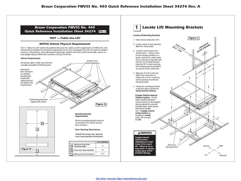
Braun
Braun FMVSS 403 quick reference
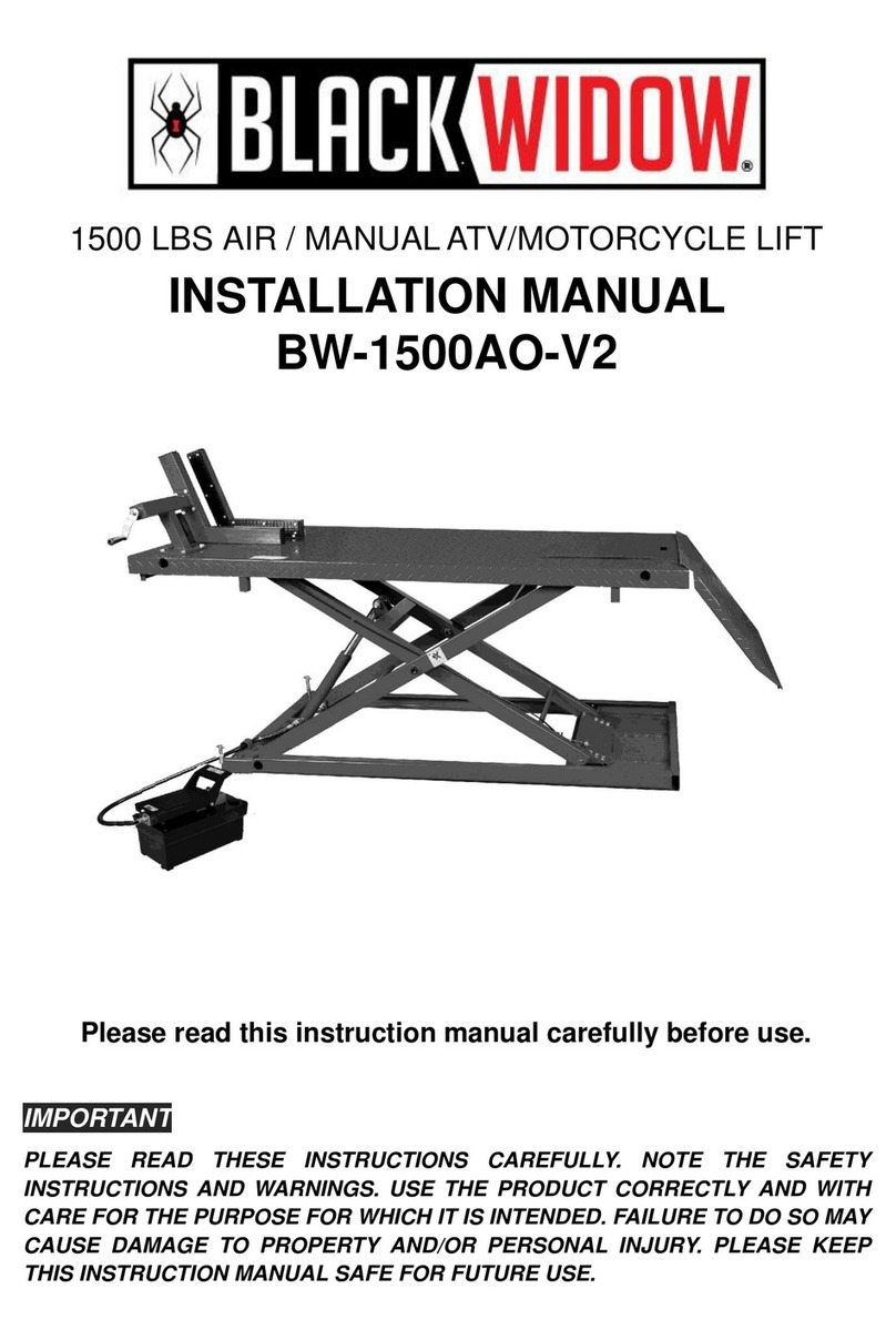
Black Widow
Black Widow BW-1500AO-V2 installation manual

SCANCLIMBER
SCANCLIMBER SC500K instruction manual
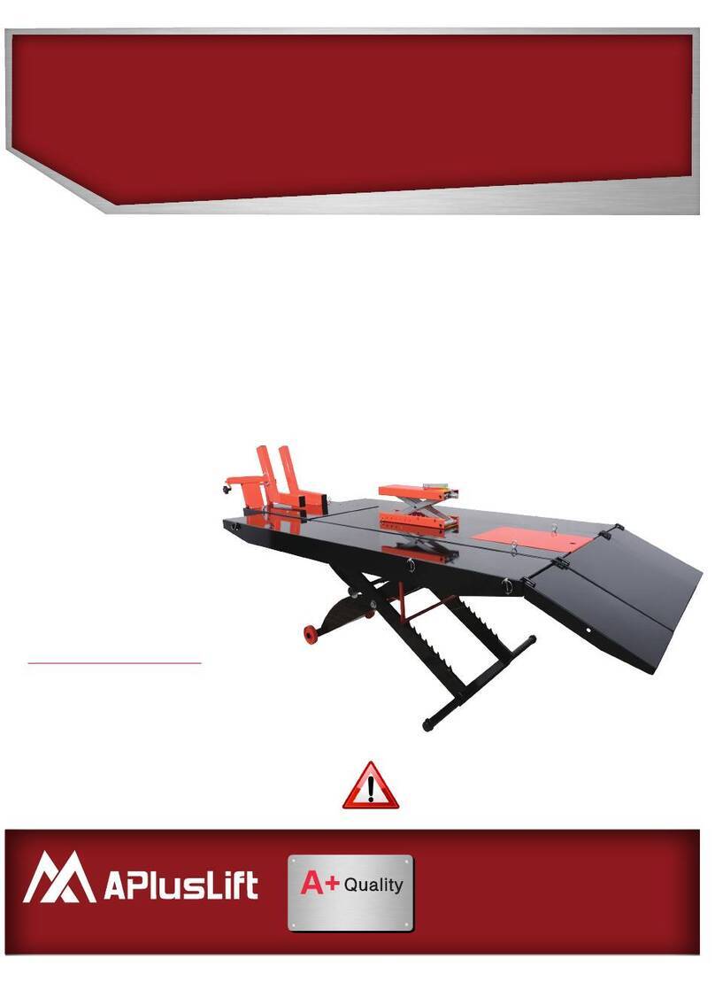
APlusLift
APlusLift MT1500 Installation manual & operation instructions
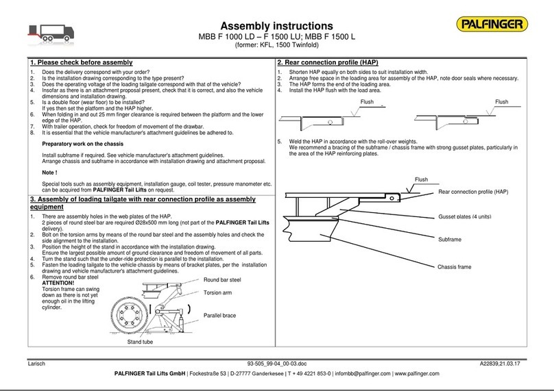
Palfinger
Palfinger MBB F 1000 LD Assembly instructions
