Gazelle G9312 User manual

P/N:
G9312
12 KV
Insulation
Resistance
Tester
User Manual

Preface
Thank you for purchasing the new G9312 insulation resistance tester. In order to use this product safely and
correctly, please read this manual thoroughly, especially the Safety Instructions part.
After reading this manual, it is recommended to keep the manual at an easily accessible place, preferably close
to the device, for future reference.
Limited Warranty and Liability
GAZELLEguarantees that the product is free from any defect in material and workmanship within one year from
the purchase date. This warranty does not apply to damages caused by accident, negligence, misuse, modification,
contamination or improper handling. The dealer shall not be entitled to give any other warranty on behalf of
GAZALLE. If you need warranty service within the warranty period, please contact your seller directly.
GAZELLE will not be responsible for any special, indirect, incidental or subsequent damage or loss caused by
using this device.
2
G9312 User Manual

3 4
1. Overview
The G9312 is a digital high voltage insulation resistance tester with 6 ranges: 500V , 1000V, 2500V, 5000V,
10000V and 12000V. Fine adjustment of voltage with 10% step at each range (except 12000V) is available.
Test data can be saved in the tester memory and transferred to a PC via the dedicated USB cable, or be
transferred to a PC in real time.
2. Features
Designed to meet IEC61010-1, CAT IV 600V and Pollution Degree 2 safety standards
For insulation resistance test, max test voltage: 12kV, max test resistance: 10TΩ, max short-circuit
current: 5mA
Automatic display of Dielectric Absorption Ratio (DAR) and Polarization Index (PI)
Large memory for saving up to 999 sets of test data
Dual power supply: Dedicated power adapter (DC15V, 1A) or 10 pcs 1.5V alkaline batteries (Lr14)
5.1-inch industrial display (320×240 pixels)
Simultaneous display of insulation resistance and leakage current values in the test
PC software for data analysis
Green light indication for POWER button and red light warning for TEST button
Auto discharge function: When insulation resistance like a capacitive load is tested, electric charges
stored in capacitive circuits are automatically discharged after testing. Discharge progress can be displayed.
Backlight Function: To facilitate working at dimly illuminated location or at nighttime
1. Overview ------------------------------------------------------------------------------------------------------------------- 4
2. Features -------------------------------------------------------------------------------------------------------------------- 4
3. Accessories ---------------------------------------------------------------------------------------------------------------- 5
4. Safety Instructions ------------------------------------------------------------------------------------------------------- 5
5. Electrical Symbols ------------------------------------------------------------------------------------------------------- 7
6. External Structure -------------------------------------------------------------------------------------------------------- 8
7. Indicators and Buttons -------------------------------------------------------------------------------------------------- 9
8. Operating Instructions ------------------------------------------------------------------------------------------------- 15
9. Specifications ------------------------------------------------------------------------------------------------------------ 31
10. Communication Function (Including Software) ------------------------------------------------------------------ 35
11. Use of Power Adapter -------------------------------------------------------------------------------------------------- 36
12. Test Probe Metal Parts and Replacement ------------------------------------------------------------------------ 37
13. Maintenance ------------------------------------------------------------------------------------------------------------- 38
Table of Contents
G9312 User Manual G9312 User Manual

5 6
3. Accessories
Open the package box and take out the tester. Please double check whether the following items are missing
or damaged.
a) User manual ------------------------------------------------------ 1 pc
b) Test leads (red, black, green, 1 each) ---------------------- 3 pcs
c) USB cable --------------------------------------------------------- 1 pc
d) Dedicated power adapter -------------------------------------- 1 pc
e) 1.5V alkaline batteries (LR14) -------------------------------- 10 pcs
If any of the above is missing or damaged, please contact your supplier immediately.
4. Safety Instructions
The tester is designed, manufactured and tested according to IEC61010 safety standards (safety requirements
for electronic measuring apparatus). It conforms to double insulation, CAT III 1000V and CAT IV 600V safety
standards. This manual contains warning information and safety regulations. Please read them carefully and
observe them strictly to ensure the safety of the user and tester.
Warning
The G9312 is a 12kV digital high voltage insulation resistance tester . Please read the Safety
Instructions in detail.
The tester outputs high voltage. Please read and understand the Operating Instructions thoroughly before use.
Keep the manual at an easily accessible place to enable quick reference whenever necessary.
Use the tester only as specified.
Please strictly follow all the instructions, or it may cause damage to the tester and user!
Please wear insulated gloves before use.
Do not measure in circuits with voltage above AC 750V or DC 1000V.
Do not test in flammable places. Sparks may cause an explosion.
Never use the tester if its surface or the operator's hands are wet.
Be careful not to short-circuit the metal part with the test leads when testing voltage or it may cause personal
injury.
Do not exceed the maximum allowable range during measurement.
To prevent damage to the tester from high voltage output, do not press the TEST button when the test leads
are connected to the tester.
Never open the battery cover during measurement.
Do not touch the circuit under test when measuring insulation resistance or right after measurement, otherwise
it may pose an electric shock.
Stop the test if contamination or carbonization which may impair insulation characteristics is found on the test
leads or around the terminals.
Avoid short circuit and open circuit of the test leads when measuring insulation resistance. Otherwise, the
measurement may be ceased and the light of the TEST button may go out.
Before use, please check if there is any item which is damaged or behaving abnormally. If any abnormal item
(such as bare test lead, damaged tester housing, broken LCD, etc.) is found, or if the tester is considered to be
malfunctioning, please do not use the tester.
Do not use the tester if the battery cover is not covered up, or it will pose a shock hazard!
When using the tester, keep fingers behind the finger guards on the test leads, and do not touch exposed
wires, connectors or alligator clips to prevent electric shock.
Select correct output voltage before measurement. It is forbidden to change the voltage during measurement
to avoid damage to the tester.
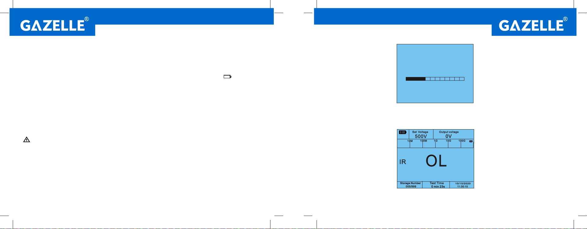
When the “ ” symbol appears on the LCD, please replace the batteries in time to ensure measurement
accuracy. If the tester is not in use for a long time, please remove the batteries. Make sure the tester is turned
off before opening the battery cover.
Do not change the internal circuit of the tester to avoid damage to the tester and user!
Do not use or store the tester in high temperature, high humidity, flammable, explosive or strong magnetic
field environments.
Clean the tester housing with a soft cloth and mild detergent. Do not use abrasives or solvents!
G9312 User Manual G9312 User Manual

7 8
5. Electrical Symbols
Description
Equipment protected throughout by DOUBLE
INSULATION or REINFORCED INSULATION
Earth (ground) Terminal
Warning or Caution
Alternating current
Direct current
Low battery
Caution, possibility of electric shock
Symbol
6. External Structure (Picture 1)
EARTH: Input terminal
for insulation sampling
test lead
GUARD: Input terminal
for grounding guard
test lead
LINE: Input terminal for
high voltage output test
lead
LCD
Buttons on the left
Battery cover
USB port
Power adapter port
Buttons on the right
Placement area for
test leads and power
adapter
Insulation sampling
test lead (black)
Grounding guard test
lead (green)
High voltage output
test lead (red)
Dedicated power adapter
HighVoltage (+) GUARD EARTH -
INSUL TIMING COMP DCV/
ACV
SET USB
OK
TEST
Pressfor > 1s
SAVE RECALL CLEAR
CURRENT
CLEARALL
NOTE:
Do not measure charged bodies. Disconnect all electrical connections before
measuring.
Turn off tester and remove all test leads before opening battery cover.Make
sure charged bodies are isolated from test leads before taking out batteries.
Contains 10 alkaline batteries (Lr14).
Picture 1
G9312 User Manual G9312 User Manual
Table of contents
Popular Test Equipment manuals by other brands

Redtech
Redtech TRAILERteck T05 user manual

Venmar
Venmar AVS Constructo 1.0 HRV user guide

Test Instrument Solutions
Test Instrument Solutions SafetyPAT operating manual

Hanna Instruments
Hanna Instruments HI 38078 instruction manual

Kistler
Kistler 5495C Series instruction manual

Waygate Technologies
Waygate Technologies DM5E Basic quick start guide

StoneL
StoneL DeviceNet CK464002A manual

Seica
Seica RAPID 220 Site preparation guide

Kingfisher
Kingfisher KI7400 Series Training manual

Kurth Electronic
Kurth Electronic CCTS-03 operating manual

SMART
SMART KANAAD SBT XTREME 3G Series user manual

Agilent Technologies
Agilent Technologies BERT Serial Getting started