gazex DG-9.E/4 User manual
Warsaw
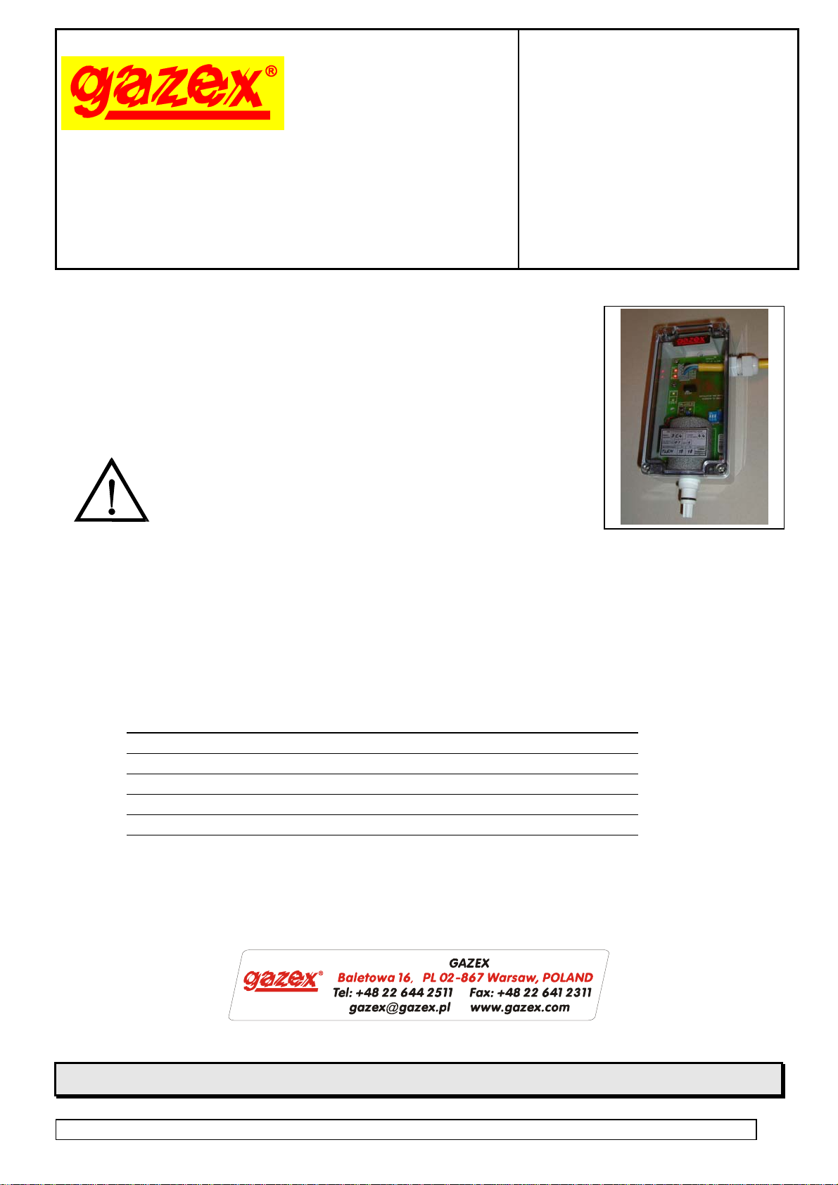
Oxygen Detector
type
USER’S
MANUAL
edition 1U5en
DG-9.E/4
series U5
Read carefully this entire manual BEFORE
installation.
The installation can be started after the
content of this manual has been fully
understood.
Follow the recommendations and
warnings provided in this manual
to maintain safety when installing
and operating the unit.
Keep the manual as reference for the User
of the Two-Threshold Gas Detection System.
1. Purpose page 2
2. Specifications 3
3. Description 4
4. Installation conditions 4
5. Installation of detector 5
6. Maintenance / operation 7
7. Warranty terms 9
PRODUCER:
PRODUCER:
©gazex ’2013 All right reserved. Reproducing and copying of this manual in whole or part without consent of GAZEX is prohibited.
Logo of gazex, name of gazex, dex, ASBIG, Active Safety System of Gas System are reserved trademarks of GAZEX
Work and live SAFER with us!!! ©gazex
DG-9.E/4 Oxygen Detector, Operation Manual edition 1U5en gazex’2013 v1301 Page 1 / 9
DG-9E/4 detector OPERATION MANUAL edition 1U5©gazex’2013v1301 2 / 9
1. PURPOSE
The stationary detector DG-9E/4 is designed for continuous control of oxygen concentration in rooms
endangered by loss or displacement RIatmospheric oxygen from air or endangered by growing oxygen
concentration. The control consists in continuous measurement of O2concentration in the surrounding air.
If concentration drops below the strictly defined thresholds or grows above the specified value,
alarm signals are tripped on two control outputs.
It is designed for interaction with MD type control units produced by GAZEX.
It has common structure and can NOT be used in zones with explosion danger classification.
Due to the incorporated thermal compensation system it may be used at variable temperature conditions.
It is provided with replaceable, electrochemical oxygen sensor.
DG-9E/4 detector will be called below in this instruction as DG.
CAUTION–IMPORTANT:
The electrochemical sensor applied in this detector is resistant to air movement in its vicinity.
It is important to avoid impact of strong air stream or its sudden changes.
The sensor’s incorporated thermal compensation system operates correctly only in temperature range
indicated below (table 2.1) - exceeding this range or sudden ambient temperature changes
may lead to the false indications.
It is necessary to avoid sudden moisture changes and absolutely avoid moisture condensation on sensor.
PROTECT detector against violent shocks and impacts => it may result in reduced durability
and changes in sensor parameters.
Protect detector against temperature increase (above +50ºC) => it results in irreversible sensor’s damage.
Concentration toxic gas or substance vapors (by item "Resistance to gases and disturbing factors" in table 2.1)
on NDSCh level (The Highest Permitted Momentary Concentration by regulation of Minister of Labor and Social
Policy) have no impact on sensor operation. Nevertheless, operation of this detector in concentration of gases
significantly exceeding such concentrations may result in permanent change in detector measurement
parameters, reduce its operation life or total damages of oxygen sensor.
Absolutely avoid impact of substances indicated as “Disturbing factors” in table 2.1 – their impact may
cause wrong measurement of O2concentration or permanent, irreversible sensor damage.
The detector operation in increased oxygen concentration conditions will reduce sensor operation life
proportionally to relation of such concentration to the regular level (i.e. 20,9%).
AREA OF APPLICATION
technical gas warehouses (nitrogen, carbon
dioxide, oxygen, etc.). premises with process
consuming oxygen
breweries the premise with oxygen systems
extinguishing and cosmetic agents bottling plants production rooms, boiler rooms
food packing premises fruit stores
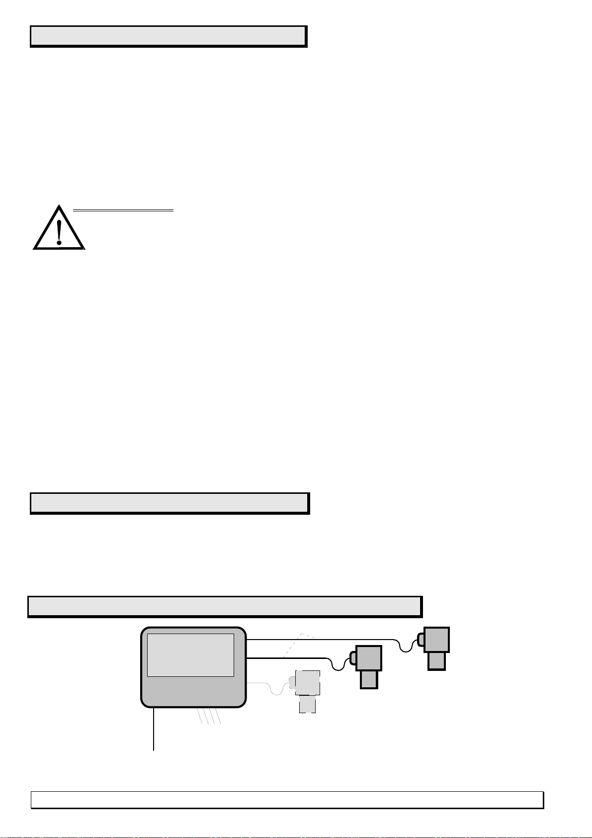
Gas detection system - connection block diagram
DG
230VAC 3 x 1,5
YDY 4 x 1
(12VDC 2 x 1.5)
...
CONTROL OUTPUTS
relays and 12VDC alarms
DG
DG
MD...
DG-9E/4 detector INSTRUCTION MANUAL edition 1U5©gazex’2013v1301 3 / 9
2. TECHNICAL PARAMETERS TABLE 2.1.
Supply voltage 9VDC= ( permitted fluctuations 6,0 ÷ 15,0V)
Current consumption typical 35mA, max 50mA
Operation temperature recommended 5C to +40C (thermal compensation range)
permitted 0C to +45C (outside compensation range);
at air humidity between 5% and 95% (without moisture condensation
on sensor )
Storage temperature optimum from +5C to +25C ;
permitted from -15C to +50C
Detected gases oxygen, range 1 ÷ 25% vol. (theoretical – up 100%)
Gas sensor electrochemical, with thermal compensation,recommended calibration
period = 6 months; operation life 4 years = ca. 900.000 [O2% x h]
in regular conditions
Measurement method diffuse
response time t90 = below 15 sec.
Resistance to gases
and disturbing factors
no effect: CO, CO2, NOX, methane, H2S, H2, argon,
air movement - no effect;
small effect (negligible at NDSCh levels): Cl2, CFCs, SO2, NH3, HCl
Disturbing factors isopropyl alcohol, hexane, CCl4
absolutely avoid: NaOH;
due to sensor’s structure: acetone and methyl ethyl ketone
Effect of atmospheric pressure. proportional (linearity 2% in range 0,5 - 1,5 atm.)
Effect of moisture (at const
ant temp and concentration)< 1% of concentration level, in temp. range . <+25C, ca 21% O2;
< 3% of concentration level, temp. range . +25C to +40C,ca 21% O2
Alarm thresholds two, in range 17 ÷ 25% v/v
Threshold concentration
levels - typical ALARM 1 = 19 % v/v
ALARM 2 = 18 % v/v; (or in above range);
exact setting see calibration certificate SSW enclosed
to each DG-9E/4 )
Calibration conditions
20,9% v/v O2, 20(2)C, RH 65(±10)%, atmospheric pressure
1013(±30)hPa, >72h continuous power supply
Alarm threshold
setting accuracy 5% of threshold level, at calibration each 6 months (internal button)
Alarm threshold 5% of concentration level (within temp.range from +5C to +40C)
stability 10 % of concentration level - long-term within 3 years
Recalibration possible local calibration (20,9%), without calibration mixture;
calibration button + LED control lamp + potentiometer as standard
equipment
Alarm signal
outputs two, transistor type OC (<20VDC=, < 50mA),
independent for each threshold; with direct connection to
MD unit possibility
Electronic systems constructed by SMD, technology, incorporated power supply and
wire connection effectiveness control system
Dimensions, weight 185 x 110 x 55 mm H x W x D (with cable gland); ca. 0,4kg
Housing ABS/PC, IP54
CAUTION:
The oxygen sensor is an integral element, in chlorinated polyvinyl chloride (CPVC) housing.
It is filled with electrolyte with weak acid reaction and includes also small amounts of lead
and its compounds, and gold. In case of mechanical damage of sensor and contact with electrolyte
the exposed area shall be flushed with plenty of water and possibly obtain the medical advice.
The applicable regulations must be observed for utilization.
DG-9E/4 detector INSTRUCTION MANUAL edition 1U5©gazex’2013v1301 4 / 9
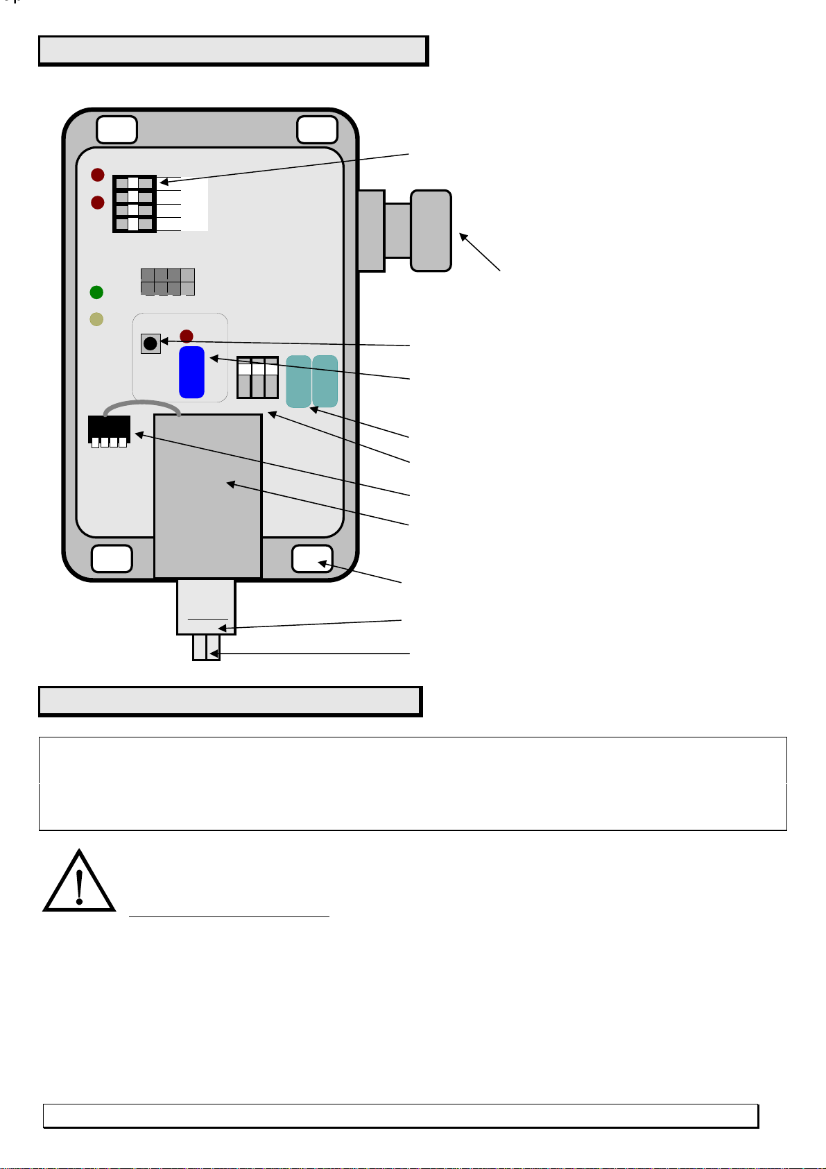
3. DESCRIPTION
The view without detector cover.
cable gland 11mm
Cage clamp cable connectors
Opening for installation on wall
20,9% calibration potentiometer and LED
CAL.x=20,9%
Px
Calibration button
Air inlet to sensor
Oxygen sensor – REPLEACABLE
Alarm threshold potentiometers
+
2
1
M
A1
A2
POWER
FAULT
PH PL
ZTEST
SENS
ZSENS
1 2 3
SW2
Dx
SWx
Threshold operation mode switch
Sensor fastening nut
Sensor connection socket
4. INSTALLATION CONDITIONS
The detector’s user and INSTALLER must be aware of special
structure and specific purpose of DG-9E/4 detector.
All installation and service operations must be conducted with the
HIGHEST CARE !!
4.1. The detector INSTALLATION LOCATION in room endangered by oxygen concentration
fluctuations have FUNDAMENTAL impact on correct detector operation from the point of view
of safety of personnel. Therefore, installation location shall be trusted to the
competent specialist.
4.1.1. It can be adopted, that the optimum detector installation location is:
on the wall or extension arm,on height ca 180-200cm above floor or on the face level of man in working
in place, where employees often reside, not further than 8m from
the potential source causing oxygen concentration fluctuations;
away from ventilation openings, windows;
away from impact of air directly breathed out by people;
place not exposed to direct sunlight, away from heat sources;
OpOp
position
and in place not exposed to direct impact of outside air, steam, water or
other liquids, exhaust gases from furnaces and other disturbing factors from table 2.1, dust.
The indicated above distance from absorbing source, displacing or emitting oxygen,applies to the
undisturbed diffusion zone, i.e. area with uniform temperature, without mechanical obstacles restricting
the gas or vapor flow, without forced air circulation, without gravitational ventilation.
All listed factors must be considered in correct arrangement of detectors.
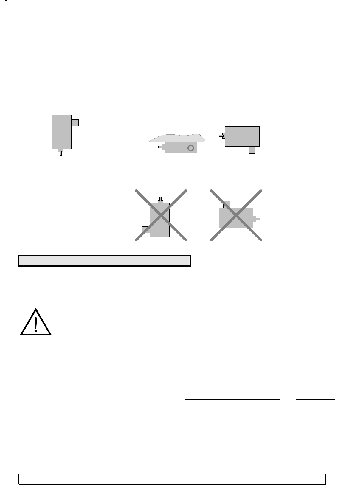
4.2. INSTALLATION POSITION: RECOMMENDED – VERTICAL (inlet to oxygen sensor downward) !
The horizontal installation is allowed – with inlet to the side provided that detector is not exposed
on to moisture or other factors, at low dust level in the supervised room.
INSTALLATION POSITIONS:
DG-9E/4 detector INSTRUCTION MANUAL edition 1U5©gazex’2013v1301 5 / 9
recommended - vertical or permitted - horizontal
PROHIBITED:
5. DG-9E/4 INSTALLATION
It is necessary to make sure PRIOR installation that detector is provided with individual detector
calibration certificate (specified alarm threshold values must be consistent with the grey
calibration label on cover).This document shall be kept and necessary transfer to the user
as this document is the base for any claims.
DURING INSTALLATION it is necessary to avoid touching the sensor with fingers
or using tools which may heat the sensor = it will disturb the sensor’s thermal balance
and increase the stabilization time to ca 20 minutes.
5.1. Disassemble the detector’s cover. Introduce 4-wire round cable through the cable gland and connect it
to detector’s connectors. The mechanical damage of printed-circuit board will cause
IRREPARABLE damage of electronic systems = need of replacement and calibration,
which is not covered by WARRANTY!!!
5.1.1. CABLES: It is permitted to use only one, -wire, exclusiYHO\ round cable.
The recommended type YDY, YKSY (or equivalents from other manufacturers); permitted - OWY, OMY;
condition : cable internal diameter can not be smaller than 5 mm and can not be higher than 11 mm;
it is condition necessary for correct cable sealing in cable gland.
There are no critical values for cross-sections due to very small currents in wires. The practical aspects
of mechanical strength of wire, accessibility and distance to module cause that the minimum
wire cross-section is recommended:
0,5 mm2at distance from MD to ca. 300 m,
1,0 mm2,, ,, ,, ,, up to 700 m (eg. YDY4x1G offered by GAZEX),
1,5 mm2,, ,, ,, ,, above 700 m.
But cables with wir cross-section 1.5mm2are NOT recommended due to mechanical problems with
wire connection to detector's connectors.
OpOpOpOpOpOpOp
Op
CAUTION. VERY IMPORTANT !

5.1.2. Wire ends: cable end introduced to the detector's connector box shall be so prepared that wires
fastened in terminals are not bent inside detector and sealing of cable gland contains the outside coating of
the cable.
5.1.3. IMPORTANT: 5.1.3. Introduction of wire to self-gripping type terminal (slant)
DG-9E/4 detector INSTRUCTION MANUAL edition 1U5©gazex’2013v1301 6 / 9
1remove wire isolation on distance exactly 9 to 10 mm
(straight) or 8 to 9mm (slant)
2. push (introduce) the bared wire end into the round terminal
opening with pliers.
The correctly introduced wire can not be moved out from terminal.
Wire can be released and taken out after pushing lever 3
(white or grey, according to arrow 3).
The clamping of wire in cable gland shall be so strong so cable
will not move out from detector by hand jerking( and
cable can not transfer mechanical forces on detector connection
terminals). This will secure correct detector’s sealing.
2.
3.
8- 9 mm
1
.
5.1.4. Screw down the detector’s cover. When assembling the cover it is necessary to make sure that the
rubber gasket is on its correct position and provides complete cove tightness.
5.2. Detector must be installed with measuring chamber directed downward or aside so inlet to sensor
is on the recommended height.
5.2.1. It is necessary to take care that detector is not exposed to mechanical damages or flooding with
water, other agents or contamination of sensor inlet.
5.3. The connection cable shall be carry to MD unit installation location or the system control panel.
The cable moved out from detector shall be "U"-shaped with "belly" directed downward, directly
at detector (it prevents water dripping on connection cable to detector's cable gland and provides the
additional length of cable for possible connecting tips corrections in the future).
When cables are run through zones available for the third persons, cable shall be run in plastic pipe
casing. This will protect system against accidental or purposeful damages.
It is recommended to use UNIFORM cable between DG and control unit.
If it is necessary to extend the cable (“lengthen”), connecting cables can be joined using the tight box with
four terminals with protection class IP54 or higher.
5.3.1. Connect:
- wires from detector outputs “1” and “2” to outputs of control unit or system central panel.
- detector 9V power supply “M” and “+” to relevant terminals in module MD or central panel..
Observe correct POLARIZATION of all wires !
The incorrect polarization of wires from outputs of DG-9E/4 detector will cause MD Alarm condition
or improper system operation.
Secure minimum 20 minutes time for equalization of oxygen sensor temperature ( after transport/
storage period) and detector installation location – the best in the cardboard package.
5.4. Connect MD control unit power supply, check system correct power supply signaling.
5.4.1.The initial sensor operation stabilization period in DG-9E/4 starts when power supply is
turned on.It lasts several seconds (it depends on environment conditions, calibration level).
ALARM 1 and/or ALARM 2 can be generated in MD during stabilization.
The unstable sensor operation condition can last even several dozen minutes in case of too high difference
of temperatures between oxygen sensor and surrounding air or if leveling of these temperatures is too fast.
Detector passes to its regular operation after this initial period (if oxygen concentration in the supervised
room does not exceed detector’s threshold values ALARM 1 or ALARM 2 !)
5.5. The final check of MD + DG system operation is the final phase of installation :
5.5.1. You must make sure that detector is correctly supplied (only green “POWER” lamp is on) and heating
cycle is over (A2 and A1 lamps are off).
5.5.2. Generate detector’s alarm conditions:

for alarm thresholds set below 20,9%:
slowly blow in sensor direction (air breathed out by man has significantly lower oxygen concentration)
Detector’s lamp [A2] and/or [A1] shall turn on in this moment (or with few seconds delay).
If there is no effect, repeat blowing with air “detained” in lugs for ca 10 s - it includes more carbon dioxide,
less oxygen. The relevant effects shall be also observed in the connected MD module.
for threshold level settings above 20,9%:
introduce portion of oxygen (technical, in gaseous form, with ambient temperature (introduce through the thin,
long flexible pipe – minimum 1 m) into sensor vicinity – effect similar to described above (or according to alarm
threshold operation mode switch); possibly increase the oxygen portion (sensor is resistant to momentary,
high, even to 100% by volume, oxygen concentration). The relevant effects shall be also observed in the
connected MD control unit.
Detector DG-9E/4 shall be recognized
as operational and started after successful result of test.
The date and name of person conducting installation and serial numbers of all units installed in System
shall be included in the Periodical Inspection Report. The individual detector’s SSW calibration
certificate shall be kept with this Report.
In case of any doubts or lack of clarity concerning installation and operation of this DETECTOR,
please contact with the Authorized Distributor or MANUFACTURER.
6. MAINTENANCE / OPERATION
6.1. Due to the multi-year durability of sensor in DG-9E/4 detector, maintenance is reduced to:
A) - periodical elimination of dust from casing and inlet to sensor,
B) - periodical inspection of system operation according to procedure 5.5 in chapter DG-9E/4 instalation
The recommended frequency of periodical
inspection at least every 3 months
C) - in case of high moisture level in the supervised room or if connecting cable or detector was exposed
to water splashes, the above procedure shall be supplemented by detector cable gland box tightness test:
- turn off detector’s (system) power supply,
- disassemble the detector’s cover,
-check if terminal chamber or connecting terminals are moist, covered with deposit or demonstrate traces
of corrosion. In such situation it is absolutely NECESSARY to dry the terminal chamber, seal the
cable gland (tighten) and secure removal of water drops in front of cable gland (orifices, covers on cable,
- assemble cover according to point 5.1.4.
D) - as oxygen sensor has natural tendency to loss its sensitivity in time (irrespective if it is
connected or power supplied), sensor must be calibrated after period not longer than 6 months from production
date (in practice from purchase date from manufacturer) or from the last calibration.
The above operation may be conducted by the user according to procedure 6.2.
E) CAUTION : IT IS NOT ALLOWED to modify PL and PH potentiometer and SW2
threshold mode switch settings ! Modification of alarm threshold settings requires specialist
equipment and can be conducted exclusively by Manufacturer or Authorized
Distributor/ Service company.
F) ALL results of periodical inspection or observed incorrectness in System operation must be
absolutely introduced to the Periodical Inspection Report under pain of loss of warranty right and relase of
Manufacturer from any liability from any consequences resulting from gas detection system operation.
DG-9E/4 detector INSTRUCTION MANUAL edition 1U5©gazex’2013v1301 7 / 9
U-recess or cable loop in front of cable gland, etc.
6.2. DETECTOR CALIBRATION
The recommended calibration
frequency: at least every 6 months
* - after 4 years from production/ purchase (according to SSW detector calibration certificate)
it is recommended at least each 3 months.
6.2.1. Make sure that
there are stable thermal conditions around the detector for at least 20 minutes;
here is no strong circulation;
detector has secured supply of FRESH, CLEAN OUTSIDE AIR ,for which we can be sure that it
includes 20,9% of oxygen !!! In case there is no such convince – provide artificial air from the bottle,
with flow rate not higher than 0,5 l/min
you must remember that DG-9E/4 outputs are active during calibration = it is necessary to notify
the oxigen detection system’s user on possibility of false alarms during calibration and to deactivate
temporary the system’s outputs.
6.2.2. Disassemble the detector’s cover. Do not touch the sensor ! DO NOT direct the brathed the d
out into detector’s direction !!!
6.2.3. Push “SWx” calibration micro-switch with the finger. Hold the pushed button for entire calibration period.
If “Dx” LED (next to SWx) is not turned on = detector is still calibrated correctly
6.2.4. If “Dx” lamp turns on – it means calibration is necessary, i.e.:
gently, slowly turn with the small screw-driver the “Px” calibration potentiometer screw,
located below "Dx lamp, in both directions, so the “Dx” red lamp turns off;
set “Px” calibration potentiometer screw in location in the center of area
in which “Dx” lamp is turned off;
CAUTION !!! DO NOT TURN screws of PL, PH potentiometers protected by seal.
This will result in loss of alarm threshold settings.
6.2.5. Release micro-switch SWx.
6.2.6. Screw down the detector’s cover.
If it not possible to turn off “Dx” lamp during calibration, it is possible that oxygen sensor must be replaced
(in particular after 4 years from production date). In case of detector operation
in atmosphere with excess of oxygen – sensor operation life will shorten !
The user can replace the oxygen sensor according to the following procedure 6.3.
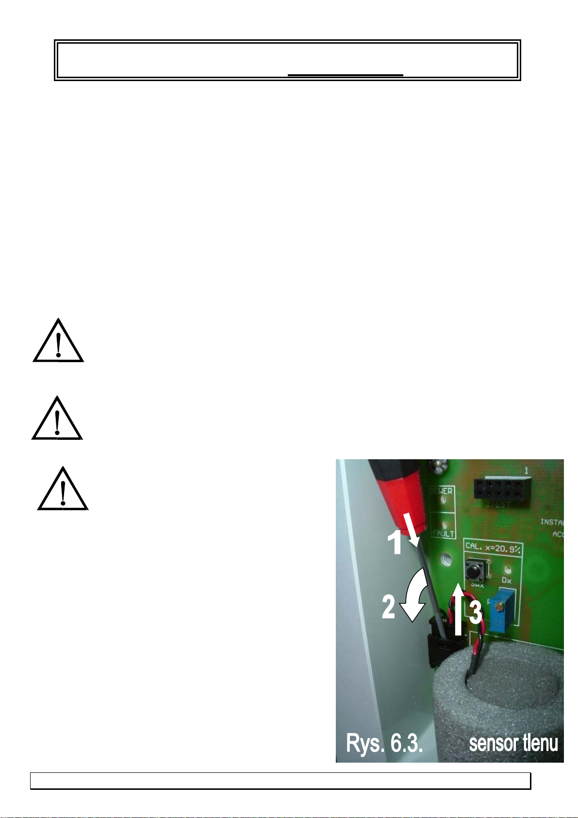
6.3. OXYGEN SENSOR REPLACEMENT
It is not necessary to switch off the
power supply for sensor replacement but you must be
very care and gentle inside the detector !
However, you must remember that detector’s
outputs can be activated during sensor replacement = it is
necessary to notify the oxygen detection system’s
User or to deactivate system outputs for sensor replacement
and calibration!
Necessary tools and materials:
- new oxygen sensor type MS-9E4 (delivered exclusively
by Manufacturer or authorized representative);
- flat or Phillips screwdriver (for cover disassembly);
-flat, thin screwdriver (for releasing the oxygen sensor
connecting inlet lock);
- flat pliers (for assembly/ disassembly of sensor inlet nut).
6.3.1. Disassemble the detector’s transparent cover.
6.3.2.Release the lock of sensor’s connecting
and remove inlet from the socket with the thin screwdriver.
The lock is released by minimal levering of socket edge center
(insertion of flat tip of screwdriver [1] from upside, on depth
ca 1 mm), and plug will remove with simultaneous screwdriver
down movement.
DG-9E/4 detector INSTRUCTION MANUAL edition 1U5
©gazex’2013v1301 8 / 9
Fig. 6.3.

according to arrow [2] on figure 6.3. Remove fully the plug from socket [3] “FAULT” yellow lamp shall turn
on then (and these A1/A2 red lamps, which shall indicate oxygen concentration lower than regular 20,9%).
6.3.3. Holding the oxygen sensor by grey insulation, grip the white sensor nut (above inlet) with flat
pliers and gently release, turning counterclockwise. Then unscrew the sensor fastening nut with fingers.
Remove sensor from opening in casing.
6.3.4. Gently insert the new sensor into opening in detector’s casing so the cable with plug is on the
connecting socket side.
6.3.5. Holding the sensor for the grey foam insulation, fix it to the casing with the white nut.
Gently “tighten” the nut with flat pliers. Sensor must be stiffly and reliably fastened to the casing.
6.3.6. Insert plug with sensor’s connecting cable to the socket – insert to hear the socket lock “click”
sound. When the sensor is correctly connected, yellow “FAULT” lamp will turn off. The condition of A1
and A2 red lamps shall be ignored until calibration of the new sensor is finished.
6.3.7. It is absolutely necessary to CALIBRATE the new sensor !!! New sensor requires
thermal stabilization for ca 20 minutes. After this period, new sensor shall be calibrated according
to procedure in point 6.2.
6.3.7. Install the detector’s transparent cover, taking care on visibility of detector’s control lamps
6.4. DG-9E/4 STORAGE
DG-9E/4 detectors shall be stored in location free of moisture, dust, combustion gases, any
chemically active substances (in particular NaOH, acetone, methyl ethyl ketone), in tightly
closed polyethylene bag, in position with sensor downward or horizontal.
Protect against strong shocks and vibrations. Storage temperature between -15°C and +50°C.
Detector shall be always stored with attached calibration certificate. After 6 months from
production date or more, calibration is required according to procedure 6.2.
6.5. In accordance with the Act on the used electric and electronic equipment dated 29. July 2005
(Journal of Laws 2005 no 180, item 1495), the used MD control unit (classified as equipment
group 9.5 under the mentioned above Act) can not be removed with other wastes.
Therefore, it is marked with special symbol.
6.6. CAUTION: due to product continuous improvement process and desire to deliver
possibly full, detailed information on these products and to provide you knowledge necessary
for correct, long-term operation of products based on the current experience of Customers,
GAZEX reserves the right to introduce minor modifications in technical specifications for delivered products
and not included in this Operation Manual and to change its content. Terefore we ask to verify and confirm
relevance of this Operation Manual edition at the Manufacturer (please provide exactly type/ make and
model of the used unit and operation instruction edition number).
7. WARRANTY TERMS
The Manufacturer shall grant GAZEX Warranty for correct operation of this detector for 12
MONTHS PERIOD from purchase date invoice if separate contract is not entered in this regard)
according to the Standard Warranty GAZEX (SGG) – available on www.gazex.pl website.
SGG warranty shall not cover oxygen electrochemical sensor. The oxygen sensor is covered by the GAZEX
Restricted Warranty (OGG3M) – according to OGG3M warranty terms – available on www.gazex.pl website.
This warranty shall not cover mechanical damages and damages resulting from incorrect storage,
installation or improper operation conditions, inconsistent with Operation Manual, in particular included in
CAUTIONS on page 2.
DG-9E/4 detector INSTRUCTION MANUAL Edition 1U5
©gazex’2013v1301 9 / 9
Delivery of individual calibration report for the given detector is the prerequisite for repairs
under this Warranty.
Table of contents
Popular Analytical Instrument manuals by other brands

Stanley
Stanley IntelliMeasure 77-018 instruction manual

Triplett
Triplett CobraCam PRO instruction manual

Beckman Coulter
Beckman Coulter CEQ 8000 user guide

PCE Instruments
PCE Instruments PCE-VE 650 manual

RIDGID
RIDGID SeeSnake DVDPak2 Operator's manual

Extech Instruments
Extech Instruments HDV600 user manual

General
General Seeker 400 Series user manual

Fluke
Fluke FI-3000 FiberInspector Pro Getting started guide

PRAGMATIC COMMUNICATIONS SYSTEMS
PRAGMATIC COMMUNICATIONS SYSTEMS HazCam Quick user guide

iSystem
iSystem Infineon TC397XE user manual

Stanley
Stanley TLM40 user manual

Seikom Electronic
Seikom Electronic RLSW4A manual


