GB XD4A User manual

~
Q
~
~
~
I-'
~
ri
~
~
~
~
~
~
~
0
~
,Q.
,Q.
=
~
~
00
0
~
=
<
I
t
I
I
CAUTIONS
1.
This machine is not intended for use by the physicallyweak, intellectually obtuse,
mentally disabled
or
children , unless it
is
safely used under the help
or
instructions
of
those who are responsible for theirsafety .
{
2.
The
childrenshall
be
supervisedto ensure thatthey will notplaythe machine.
3.
Be
sure to remove the powerplug from the socket before cleaning
or
repairing the
machine.
4.
In
the event
that
the
power
cables are damaged
or
loose , please have them
replaced by the manufacture service station
or
qualified technician . The
connection is Y-type connection .
5. Remove thepowerplug aftet the shutdown
of
the machine.
6.
Use appropriate voltage and :frequency.
CONTENTS
Product Introduction-------------------------------------------------------------- 1
Safety Considerations ------------------------------------------------------------ 1
Main Structure--------------------------------------------------------------------- 1
Operating Procedures and Precautions----------------------------------------- 2
Care and Maintenance------------------------------------------------------------ 2
Main Troubles and How to Solve Them --------------------------------------- 3
Included Accessories ------------------------------------------------------------- 3
Techrlical Parameters ------------------------------------------------------------- 4
Explosion Views------------------------------------------------------------------- 5-9
Product Introduction
Welcome to buy and use XD4A Sweeper-Drier. This machine is featured in easy
operation, safe use and good cleaning effect, suitable for cleaning
of
the small-
and medium-sized grounds in office building, hotel, warehouse and square.
Safety Considerations
1.
This machine is not suitable for cleaning the carpet.
2.ln the event that the recharger
or
electric cable
is
damaged, please immediately
contact the manufacturer
or
its authorized service center.
3.Never mix different types
of
cleaning agents; otherwise toxic gas will be
generated.
4.Never use this machine in explosive environment.
5.Never use this machine for suction
of
inflammable liquids.
6.Never use the acid liquids that can damage this machine.
7.Make sure to shut down this machine and disconnect the battery before
maintenance.
8.Never clean this machine with high-pressure
jet
water or corrosive substances.
9.In case that the machine is caught to fire, please ililJllediately use powder
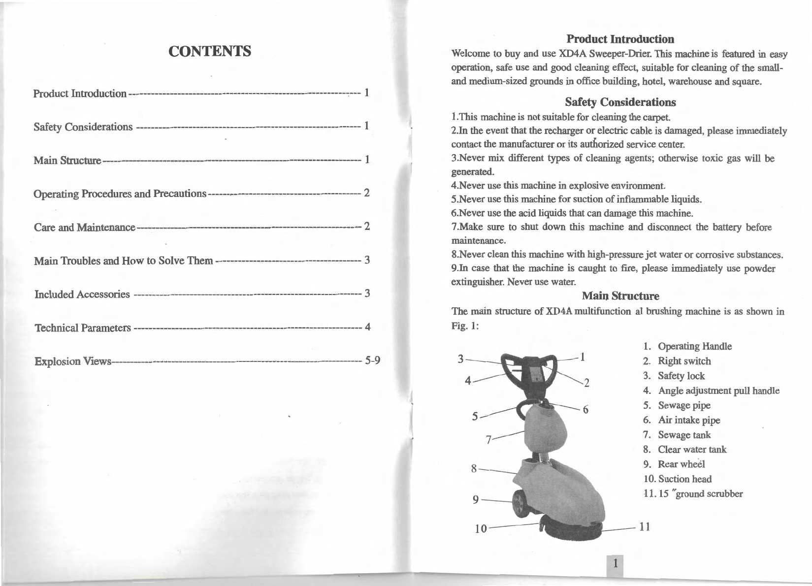
extinguisher. Never use water. Main Structure
The main structure
of
XD4A
multifunction
al
brushing machine is as shown in
Fig.
1:
l.
Operating Handle
3--.:::-m
2.
Right switch
4 3. Safety lock
4. Angle adjustment pull handle
5.
Sewage pipe
6. Air intake pipe
7. Sewage tank
8.
Clear water tank
9. Rear wheel
10.
Suction head
11.
15
"ground scrubber
11
1

Operating Instructions
1.
Unpack the machine and take it out from the base plate.
Place the machine on ground and mount cleaning
scrubber.
2.
As
shown
in
Fig.
1,
adjust the angle adjustment pull
handle to 90 °- 120
°.
Then, remove the clear water tank.
Unlock the two clamps on the battery compartment
at
the
back
of
machine and connect the battery to a fixed socket.
3. Install the battery compartment cover and clear water
tank. Add
an
appropriate quantity
of
cleanser solution.
4.
Install the sewage
tank
to the hook on the aluminum
pipe ofoperating handle, and connect the suction pipe and
sewage pipe to the sewage tank.
5.
Put down the suction head UP/DOWN handle on the
back
of
machine (Fig. 3).
In
this case, the suction head
has been flatly placed on the ground. Pull the angle
adjustment handle to adjust operating handle to the height
desired
by
the operator. Then, release the handle.
6.
Put the main scrubber switch
(I),
pumping switch (2)
and solenoid valve switch (3) on the panel
of
operating
handle to "ON" position. Check
if
the signal lamp is
bright (green). Then, push the safety lock on operating
han
dle to center, and closethe hand-operated switch, so
that the machine will start to work.
Fig.2
Care and Maintenance
@ I.Main
scrubber
switch
2.Pumping switch
3.Solenoid valve
switch
To extend the service life
of
the machine and enable the machine to work under the best effect,
it is suggested to do the following after each use:
1.
Use
clear water to wash the suction head clean and wipe with dry cloth.
2. Remove the sewage tank and use clear water to wash it clean. At the
same
time, use water to
rinse the suction pipe clean.
3. This machine cannot be wash directly with water,
but
be wiped with semi-dry cloth, thus to
ensure that no water will enter into the machine. Otherwise, the electric parts
of
the machine
will be burnt.
4.When the machine is to be put long out
of
service,
the battery shall be reguJarly recharged;
01herwise the service life
of
the battery will be reduced.
2
Main Troubles and How to Solve Them
Trouble Cause
How
to Solve
The
power
socket is not properly Connect the power socket
No
power
supply connected properly
The
main scrubber switch is not Check and put
it
to
ON
put to
ON
position. position.
The
suction pipe is blocked Check and wash the suction
pipe
No
suction force
or
the
The
sewage tank cover is not Reinstall and seal the
suction force is low installed properly sewage tank
cover
properly
The
pipe connection is not tight
Check
and repair
The
suction carbon brush is worn Replace the carbon brush
The
hand-operated
power
switch Replace the
power
switch
The
scrubber motor is burnt Repair
or
replace the
motor
cannot rotate after it is
The
scrubber motor is burnt Repair
or
replace the circuit
energized
The
circuit board is failed board
The
carbon brush
of
motor is Replace the carbon brush
of
worn motor
The
carbon brush
of
motor
is
Replace the carbon
The
suction motor worn brush
cannot rotate after it
The
motor is short circuited Repair
or
replace
is
energized and burnt Repair
or
replace the
The
circuit board is failed circuit board
The
battery
is
short circuited Replace with a new
or
aged battery
The
battery cannot
be
The
recharging circuit is short Repair
or
replace
the
recharged circuited
or
burnt recharger
The
insert connecting the Check and repair
recharger is in poor contact
The
circuit board is failed Repair
or
replace
The
solenoid valve is short Replace
tl1e
solenoid
There
is no water out circuited valve
during working
The
drain pipe is blocked Check and clean the pipe
The
drain switch is not put to Check and put it to
ON
ON
position. position.
Included Accessories
1.Machine, 1set
2.
Groundscrubber, 1
pc
3.
Sewage tank, 1 pc 4. Clear water tank, 1pc
5.
User Manual, 1 copy
3

Technical Parameters
Rated
power
I rated volatge
500W
I 12V
Working width
370mm
Width
of
suction head
440mm
Working efficiency 1350m2Jb
Scrubber diameter
370mm
Scrubber speed 165rpm/min
Scrubber motor 250V/W
Suction motor 250V/W
Clear water tank volume
UL
Sewage tank volume
llL
Battery 12V/85AH
Battery recharger 12V/20A
Battery compartment size
(L
x W x
H)
285Xl
75X235
mm
Length
of
machine after folding
970mm
Height
of
machine after folding
460mm
Net weight 67KG
Gross weight 79.5KG
Packaging size
(L
x W x
H)
l l IOX560X485rnm
l
4
Erating Handle Sub-assembly
1.
Front cover
of
handle
2.
PA5Xl0
3.
Flat washer
4.
NutMl2X3
5.
Round switch seat
6. Round switch
7. Self-lock nut M5
8. Angle adjustment handle
9.
BAH3.5XJ6
10. Cable clamp (fine)
11
. Handle spring
12.
Pin
13.
Circuit board
14.
Steel PA3Xl0
15
. Terminal strip
16.
Safety lock
17
. Left switch
18.
Back cover
of
handle
19.
BBH5Xl6
20. Right switch
21. TM6X25
22. Pull rod
of
handle
23. Spring
2Xl7X75Xl5N
24. Nut,
M5
25
. Washer
26. Needle tooth
27. Sewage tank support
28. Steel PM5X10
29. Steel CMSX45
30. Aluminum tube
of
handle
31. Self-lock steel nut M6
32. Suction head mechanism
33. Steel outer hexagonal
6Xl5
34. Steel outer hexagonal 5x20
35. Rubber casing
M8
36. Self-lock nut
M5
37. Steel outer hexagonal 8X25
38. Suction head mechanism
39. Steel set screw KM6Xl2
40. Clutch cable
41. Steel outer hexagonal 6X72
42. Steel outer hexagonal 8x20
43. Handle seat
44.Handle seat casing
45.Steel outer hexagonal
6Xl0
46.Slotted pin 4X20
47.Round tooth
48.Self-lock steel nut M6
<16
3
.........--4
-
~17
2~-~
',,,
~
--,\,
6 : 5
',,
-----
~
','
g 7
JO
'•,
_.../19
~
"
9
"-
---
'-..
----
-
"'
\ -
---------,
__
,
..
.
--
>
~20
-
~~12
11
.-
29
30
22
28
.\...-
-
t·
27 \ . 0 34
~35
-3
-
~-I
~~6
37
~~
--
---
'-=:::=
----:
~
38
23~
l:~-Jn
----32 / I 39
33
!.
_
25---.;-24
6---f
45
2 ' /
~----
-
----------
-
:
.
41--"~~
~ :
:,_
;
~:
;·
:
<_46,
'
'
42
~-
r .
43 44 -----
._--48
..
47
43 B
5
40

Water Tank I Support Sub-assembly
1.
Air
intake pipe
2. Sewage pipe
3. Sewage tank cover
4. Sewage tank seal ring
5.
Air
intake pipe connector
1-n
172
3
'.!
Q ;
' '
: :
6.
Air
intake pipe seal
ri
ng
7. Floating ball support
and
floating ball
4-+9
:
s
---1:l
i'
f
6~
'
1:
8. Sewage pipe
join
t
9. Sewage tank seal ring
10. Sewage tank
11. Clear water tank
cover
12. Clear water tank filter
13
.
Clear
water tank
14. Iron box cover
15. Copper nut
of
iron box
16. Steel carriage 6x20
17. BatteryD
CI00-12V
85AH
18
. Recharger decoration
cover
19
. Recharger
20
. Battery iron compartment
21. Clamp
22. Steel carriage
LOX25
23. Rear wheel axle 200X50
24
. Rear wheel
25. R
ear
wheel axle sleeve 200X50
26. Bearing 6024
7~
/
F-
'
0 : 8
--
·
,'
_____
;---9
IO
Connection A
11
---q
13
14
Connection B
15~
17
:{]
~1
8
29. Steel outer hexagonal 8x20 e
a==~
30
. Wheel cover I 20
19
31. Steel carriage SX18
..,....,_-(j-n.
~
·
27. Steel spring washer
M8
28. Washer
8X25Xl.5
ur
-
-(j.
' · ·
21
32.
Ste~l
self-lock nut M8
-,
! · ·
--
--
.ft
~
33. Mam frame :
..
·• 26
34. Supporting plate
of
iron box 22 l
;
~
}
/~
~j
27
29
32--/-
31
::
23 I
\L\
ii
24 28 30
~
'
25 \
33
~
-:
..
:
:
'
'
'
34~
__
_!
6
Pumping System Assembly
4 0 -
----:
~
---
'
...
--""
...
, :
3
.,..
...
: I
1
~
~()
10
1
\ I I 1\
:~
\
13
•
••
~
8--;-~
-:
~
~
~
,~_-
:
:-
~
~
11-..........
_
~
18
//
E!J-'f!J-
··l/J
--A
:
-
;~.
_
;
' - -
°IJ'.
''
~
--
.
5 /
'.
i
14Y.r
15~16
6 7 : :
·-
- i
l.
2.
3.
4.
5.
6.
7.
8.
9.
Self-lock nut
M6
Fan supporting plate
Small motor ring
i
---
-+-
-;--
-
--
-----
)' : U
J:Lm-...11
19
~:
~
20 -
··
Suction motor 12V 250W
Terminal box 120x120x60 (upper
cover
)\·
-~
Circuit board
21~~
Terminal box 120x120x
60
(l
ower
cover
)
--
Self-lock steel nut
M6
22
~
Clear water tank supporting plate
~
10. Steel carriage 6x20
!?
----
~-.
.'
\ 1... -
.
.
.
'
.
'
'
11. Screw
M8
T----
- ·24
12
.
Clear
water tank fixing nut 25
13
. Steel outer hexagonal 10x20
14
. Star washer
15
. Steel outer hexagonal
6Xl5
16
. Steel outer hexagonal 8X25
17
. Steel outer hexagonal 6X88
18.
Main
frame
19
. Suction head assembly 28
20. Steel
se
lf-lock nut
M8
21.
Power
system assembly
22.
Belt
770JB channel
26n
'!
'r
27~
I I I I 1 1
'.
7
23.Steel
PM4Xl0
24.Steel spring washer
25.Scrubber cover
26.Scrubberclamp screw 154
27.Scrubber clamp 154
28.15 "ground scrubber

Explosion View
of
XD4A Power System Assembly
I.
Brush
motorSHWT70098 l
2V
250W
2.
Central
ax.is
of
pulley
3. Steel self-lock nut
M8
4. Washer 8X20X2
5. Fan supporting plate
6.
Movable
copper
washer
7.
Motor
fixing plate
8. Washer for central
ax.is
of
puHey
9. Spring (37 #)
JO
. Steel PM5XJO
11. Steel set screw
KM6Xl
2
12. Steel spring washer 6
13.
Steel outer hexagonal 6X
15
14.
Solenoid valve 12V
15. Iron piece
of
drain valve
16. Water
jacket
17. Self-lock steel nut M5
18. Steel outer hexagonal 8x20
19. Steel set screw KM8X20
20
. Pressure regulating iron
21. Washer
l2X23Xl.5
22. Bearing 6001
23.
Belt
wheel
ax.is
24
. Bearing
6204
25. Steel
nut
M8
28~~
26
. Steel spring washe
27.
Belt
bearing casing
28. Pulley
29
. Flat washer 15X28X2.4
30. Nut for central axis
of
puJJey
31.Flange
32.Flange
plug
33
.
Washer
of
three-blade
impeller
34.Three
-b
lade
impeller
35.KCM8X50
• : 30
31
-'
I<
I I
32
i~
:
' '
' '
: I :
33
~~
+
3
4~
~
35-ti i
8
Suction HeadAssembly
1----w
5 •
(10
2~
~
----
69
v---
~--
JL::
7 ·--.,·
-~.
13
3
__...,
llY-W,
•'
c
4_____!
6/'
71
-:
/i
.14
r-10
_/r
~17
l.
Rotating shaft
of
suction head
2. Rotary support
3. Washer
6Xl2Xl
4. Steel set screw KM6X15
5. Landing
bar
6. Pressure spring
of
suction hea d
(l.6Xl
7 inner 3.5 torsion spring)
7. Torsion spring fixing shaft
8.
Washer
6X20Xl
9. Self-lock steel nut
M6
10.
Set
screw KM6X40
8 9
15 ..,,,., 18
2U
: .U
14
::
~
·
~
2 1
I l!i I
I : : '
22--+d=d
2
~
'
/
..
;:
~;
•
/
I :
, /'
:
~
--~---:--
·
<\,,-·
10
24
rp::;==7T
?O.::
~_i__N
~
:
,',4
/
,/'
•
,-'
------
,
Cl
25
F / 'j ,.-
~
11.
Landing block
12. Self-lock steel nut
MS
13.
Steel outer hexagonal 5x28
14. Self-Jock steel nut M6
15. Connection block
of
suction head
16.
Star head screw M6
17.
Steel machine screw 6X40
18
. Steel outer hexagonal 6X35
19. Steel outer hexagonal
6Xl5
20. Joint
of
suction bead
/
/
//-~~-/
/
27~
~/
12
30_;:::®
-/
21. Weight bar
22. Rear pressure board
of
suction head
23. Rear pressure strip
of
suction head
24. Suction bead casting
25. Front rubber strip
of
suction bead
26. Front pressure board
of
suction head
27. Steel carriage 5x20
28. Steel carriage 5x30
29. Steel carriage 5x35
30. Small rubber roller
of
suction head
9
Table of contents
Other GB Scrubber manuals

Popular Scrubber manuals by other brands

Drieaz
Drieaz HVE-LL Large Loss Operation and service manual

Servpro
Servpro 879 Information & operation manual

Dadant
Dadant M00432 Assembly, Operation, Maintenance, Replacement Parts

Crescent
Crescent SC800 User and maintenance guide

Hydro-Force
Hydro-Force Nautilus MX3-500HE operating manual

Ready Rack
Ready Rack EW30 owner's manual


