Techne FSSR1 User manual

Issue 1
02/07
FSSR1
Venturi Scrubber Unit
OPERATOR’S MANUAL

Contents
Section Page
1. Introduction 1
2. Installation 1
3. Start-Up 1
4. Normal Operation 1
5. Shut-Down 2
6. Maintenance 2
7. Suggested Spares 2
Appendix 1 Scrubber Layout Drawing
Appendix 2 Operating and Maintenance Instructions for Pump

1
1. Introduction
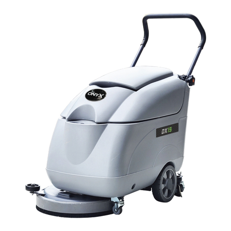
The scrubber is a Venturi scrubber designed to recirculate water to remove
fumes from a gas stream. The primary design of the scrubber is the removal of fumes
from a furnace installation however, it can be used for a wide variety of applications.
Absorption of fumes is achieved in the spray venturi contact with scrubbing liquor
recirculated by a sump pump from the column sump tank.
A General Layout Drawing of the unit is included in the documentation manual.
2. Installation
The scrubbing unit should be sited on a level surface. It is recommended the base frame
be through bolted to the floor.
The gas inlet and outlet are of plain spigot arrangement, the connecting flexible duct
should be secured with jubilee type clamps.
The scrubber should be connected to a water supply. The connection is a ½” BSP female
threaded connection as labelled, it is generally recommended an isolation valve be fitted
in the water supply to the scrubber.
The drain connection may be connected to a suitable drain. This is not essential as liquid
should not be discharged during normal operation.
The pump should be connected to a single phase 240V supply. DO NOT RUN DRY.
3. Start-Up
Following installation or a shut-down period the integrity of the scrubber unit should be
visually checked.
The position of valves should be as follows: Drain Valve :Closed
Sampling Valve :Closed
Recirculation Valve :Open
The water supply can then be turned on to the scrubber and allowed to come up to level.
The scrubber is fitted internally with a ball float valve, this will maintain the correct liquid
level in the scrubber.
Once the liquid level has reached operating level the pump can be switched on and the
system inspected for leaks.
NOTE: DO NOT OPERATE THE PUMP WITH NO WATER. RUNNING THE PUMP DRY
WILL CAUSE SIGNIFICANT DAMAGE.
Having ensured there no leaks, the unit is ready for normal operation.

2
4. Normal Operation
Note:
Prior to operators carrying out any work on this unit, they must be advised of the
hazardous nature of the chemicals involved and the emergency procedures to be
followed in case of personal exposure.
The sump should be filled with the appropriate scrubbing solution. The unit is designed
for using fresh water, however caustic soda may be added through the level gauge to
improve scrubbing performance (normally a 5% Caustic Soda solution). The level in the
sump will fall slightly due to the water in the pipework but will be made up automatically,
this is normal and the operating level should be noted.
The scrubber is now ready for use. The air stream containing the fume to be removed can
be vented through the scrubber.
Over a period of time the recirculation liquid will suffer evaporative losses, the operating
level will be maintained by the automatic addition of water.
As the scrubber absorbs and neutralises fumes, the scrubbing solution will become
contaminated or, if added, chemical in the scrubbing solution will be used up. The fluid
should be checked on a regular basis to maintain the optimum efficiency of the unit. As
necessary, scrubbing liquor can be bled to drain from the drain valve, being made up
automatically with fresh water, or more caustic added. Continuous addition of more
caustic will cause salt build-up and possible crystallisation causing damage, it is therefore
recommended to occasionally drain down the scrubber and refill with fresh water.

3
5. Shut-Down
If the scrubber is to be shut-down for inspection, cleaning, or for any other reason the
sump should be flushed with fresh water several times to remove any chemical residues.
The make-up water should be isolated and the sump drained through the drain valve. The
pump should not be allowed to run dry.
The lid of the scrubber can then be removed and any remaining deposited solids
removed.
6. Maintenance
Other than the maintenance of the pump, refer to appendix 2, the scrubber will need little
regular maintenance.
The internal assembly is simple and strip down for inspection straight forward.
•Turn off and drain the scrubber tank.
•Remove the recirculation pipe by splitting the unions at the venturi and above the
pump.
•Unbolt the two pairs of metal flanges and remove the venturi.
•Unbolt the tank lid and lift out.
•Lift out the upper mist eliminator grid and eliminator pad.
•Re-assembly is reverse of removal –carefully ease the inlet pipe through the
eliminator pad.
The unit should be regularly checked for leaks and these should be rectified immediately.
Inspect the internals on an regular basis to check for any damage or deterioration.
Should the spray nozzle become blocked it is removed by unbolting the flanges above
and below the venturi, disconnecting the recirculation pipe and removing the venturi
assembly. The nozzle is unscrewed using a box or basin spanner from the lower end of
the venturi throat.
7. Recommended Spares
For 2 years operation we would recommend the following spare parts are kept;
a) Demister Pad
b) Pump
c) Float Valve
Miscellaneous gaskets and fastenings

4
8. Additional Notes –Following Site Inspection June 07.
Usage of the scrubber is currently un-quantified so inspection and testing routines should be
more frequent until appropriate routines are established. It was noted during the site
inspection that large quantities of solids were being deposited in the scrubber and it may be
solid deposition rather than chemical levels that determine flushing cycles.
The scrubber is mainly designed to deal with HCL gas which is easily water soluble. Precise
control of chemical concentrations and levels is not required. HCL dissolved in fresh water
turns it acidic, the more acidic the recirculation liquor in the scrubber the less efficient it will be
at the removal of HCl. Addition of alkali caustic soda reacts with the HCL in the liquor to
lengthen the time the scrubber remains efficient. Continuous addition of more caustic will
cause salt build-up and blocking of the scrubber, the scrubber content should be drained and
refilled with fresh solution to prevent this. Monitoring of the state of the liquor can be simply
carried out using litmus paper or equivalent.
The caustic solution concentration is not critical, we would recommend below 15% and state
5% as a nominal value.
Caustic soda reacted with HCL gives common salt, provided the pH is neutral the scrubber
liquor should be fit to dispose down the drain, however this takes no account of any other by-
products of the furnace. This should be determined by chemical testing.
The problem of scaling due to hard water was raised. Caustic solution will exacerbate this
problem. However the scrubbing system is resistant to chemical attack so can be descaled
using a mild acid solution (or allowing the scrubber liquor to become acidic).
For the purposes of cleaning, the inside of the scrubber can be pressure washed. The mist
eliminator pad should be gently manipulated to aid solid break up and then pressure washed.

1
Appendix 1
Scrubber Layout

A3

Appendix 2
Operating and Maintenance Instructions for Pump

Read this manual before use of product
MD SERIES
Instruction Manual
IWAKI
Magnetic Drive Pump

Types of Symbols
Indicates that “Warning” or “Caution” must be exercised. Inside this
triangle, a concrete and practical image provided as a warning or cau-
tion message is depicted.
Indicates a prohibited action or procedure. Inside or near this circle, a
concrete and practical image of the activity to be avoided is depicted.
Indicates an important action or procedure which must be performed
or carried out without fail. Failure to follow the instructions herein
can lead to malfunction or damage to the pump.
Thank you for having selected the Iwaki Magnetic Drive Pump
MD series. This manual deals with the correct handling and
operation procedures and troubleshooting methods for the
pump. To make maximum use of the pump and to ensure safe,
long operation, please read this manual carefully prior to
operating the pump. Pay special attention to the “Warning” and
“Caution” sections as they relate to matters of safety and
proper usage of the pump.
Nonobservance or misapplication of the
contents of the “Caution” section could
lead to serious physical injury to the user or
serious damage to the product.
Warning Nonobservance or misapplication of the
contents of the “Warning” section could
lead to a serious accident, including death
or injury.
Caution
Important Instruction
Contents
Chapter Page
1. Safety Instruction ···································································· 1, 2
2. Unpacking and Inspection ·························································· 3
3. Operating Principle ····································································· 3
4. Identification Codes ································································ 4, 5
5. Specifications ········································································· 6, 7
6. Outer Dimensions and Performance Curve························· 8 ~ 13
7. Main Parts and Label ································································ 14
8. Name of Parts············································································ 15
9. Handling ··········································································· 16 ~ 18
10. Installation, Piping, and Wiring ······································· 19 ~ 23
11. Operation ·········································································· 24 ~ 26
12. Causes of Trouble and Troubleshooting ··································· 27
13. Maintenance/inspection and consumable parts ························ 28
14. Application of warranty ···························································· 29
For the Safe and
Correct Handling of the Pump
• Read the “Safety Instructions” sections carefully to prevent acci-
dents involving your customers or other personnel and to avoid
damage or loss of other assets. Always follow the instructions and
advice found in these sections.
• Observe and abide by the instructions described in this manual.
These instructions are very important for protecting pump users
from dangerous conditions and situations related with the use of the
pump system.
•The symbols relate to the following meanings described below:

- 1 -
1. Safety Instruction
Warning Caution
●Turn off the power supply.
Working without disconnecting the power supply may
cause an electrical shock. Before engaging upon any work-
ing procedures involving the pump, make sure to turn the
power supply switch off and to stop the pump and other
related devices.
●Terminate operation.
When you detect or become aware of a dangerous sign or
abnormal condition during operation, terminate the opera-
tion immediately and start it from the beginning again.
●For specified application only.
The use of a pump in an application other than those clear-
ly specified may result in injury or damage to the pump.
Use the pump strictly in accordance with the pump specifi-
cations and application range.
●No remodeling.
Never remodel a pump. Otherwise, a serious accident may
result. Iwaki will not be responsible for any accident or
damage of any kind which is caused by the user remodel-
ing the pump without first obtaining permission or instruc-
tions from Iwaki.
●Wear protectors.
If you touch or come in contact with any type of hazardous
chemical liquid, including but not limited to chemicals,
you may experience a serious injury. Wear protective gear
(protective mask, gloves, etc.) during the pump operation.
Electrical Shock
Prohibited
No Remodeling
Wear protective
gear
●Qualified operators only.
The pump operator and pump operation supervisor must
not allow any operators who have little or no knowledge of
the pump to run or operate the pump. Pump operators must
have a sound knowledge of the pump and its operation.
●Specified power only.
Do not operate the pump on voltage which is not specified
on the nameplate. Failure to do so may result in damage or
fire. Only the specified power level is to be applied.
●Do not wet or dampen.
If the motor or wiring cable becomes wet or dampened
with the operating liquid by mistake, this may result in a
fire or cause an electrical shock. Install the motor and
wiring cable in positions which are not likely to become
wet or dampened with any liquid.
●Ventilate.
Poisoning may result during an operation which involves
toxic or odorous liquid. Ventilate the operating site suffi-
ciently.
●Spill-out accident.
Protective measures should be taken against any accidental
spill-out or leakage of the operating liquid as a result of
unexpected damage on the pump or the related piping.
Prohibited
Prohibited
Prohibited
Caution
Caution

- 2 -
●Operating site must be free of water and
humidity.
The pump is not designed to be water-proof or dust-proof.
The use of the pump in places where water splashes or
humidity is high may result in an electrical shock or short
circuit.
●Do not damage power cable.
Do not scratch, damage, process, or pull the power cable
forcibly. An extra load onto the cable, such as heating the
cable or placing something heavy on the cable, may dam-
age the cable and finally cause a fire or an electrical shock.
●Do not cover the motor.
Running a covered motor may accumulate heat inside the
motor and cause a fire or a mechanical failure. Ventilate
the motor sufficiently.
●Arrange grounding.
Do not operate the pump without connecting the grounding
wire. Otherwise, an electrical shock may result. Make sure
the grounding wire is connected with the grounding termi-
nal.
●Install an earth leakage breaker (option).
The operation of a pump without using an earth leakage
breaker may cause an electrical shock. Please purchase an
optional leakage breaker and install in the system.
Prohibited
●Power cable cannot be replaced.
Never use a damaged or affected power cable. Otherwise,
a fire or an electrical shock may result. Handle the power
cable carefully, as it cannot to be replaced by a new cable.
(The complete motor must be replaced in that circum-
stance.)
●Limited operating site and storage.
Do not install or store the pump in the following places:
* Places where a flammable gas or material is used or
stored.
* Places where the ambient temperature is extremely high
(40°C or higher) or extremely low (0°C or lower).
●Do not drain the liquid in the site.
The liquid discharged out of the pump, including a haz-
ardous chemical liquid, must be drained into a special con-
tainer. Never drain such liquid directly onto the floor in or
near the operation site.
●Disposal of used pump.
Disposal of used or damaged pumps must be done in
accordance with the relevant local laws and regulations.
(Consult a licensed industrial waste products disposing
company.)
●Countermeasure for static electricity.
When low electric conductivity liquid such as ultra-pure
water and flour inactive liquid(e.g.FluorinertTM) are han-
dled,the static electricity may be generated in pump,which
may cause static discharge and break down of pump. Take
countermeasure to avoid and remove static electricity.
Caution
Grounding
Electrical Shock
Caution
Prohibited
Prohibited
Caution Caution

- 3 -
2. Unpacking and Inspection 3. Operating Principle
[1] Do the model, flow and head
indicated on the nameplate
correspond with your order?
[2] Has the pump or any part of it
been damaged as a result of
accident or handling during
shipment?
The centrifugal pump is driven by pair of magnets which are
incorporated in the impeller and motor shaft. The sealless pump
structure eliminates shaft seals such as conventional mechanical seals
because the pump chamber is shielded by the casings and the impeller
is operated by the magnets. The combined coupling torque of the
drive magnet and impeller magnet gives sufficient driving power
against the motor torque.
Impeller
Suction
Discharge
Drive magnet
Driven magnet
Spindle
After unpacking the product, check the following points.
If you find any discrepancy, please contact your dealer.
2P404737
5
Iwaki Magnet Pump
MAX.CAPACITY
MAX.HEAD
RATED VOLTAGE
RATED POWER CONSUMPTION
RATED FREQUENCY
INDOOR
SINGLE PHASE (1φ)INDUCTION MOTOR
CAPACITOR-RUN
POLES
VOLTAGE
FREQUENCY
CURRENT
OUTPUT
MFG.No.
MODEL
r/min
m
V
W
Hz
MAX.LIQUID TEMP.80°C
rpm
CONT.
µF
IWAKI CO.,LTD.
TOKYO JAPAN
V
Hz
A
W
SPEED
RATING
CAPACITOR
INSULATION CLASS E
DO NOT RUN PUMP DRY

- 4 -
4. Identification Codes
1 Series type MD-15R, MD-20R, MD-30R, MD-40R, MD-55R
2 Pump type X: High flow rate type Z: High head type
No symbol: Standard type
3 Suction/discharge port type M: Threaded connection No symbol: Hose connection
4 Power source voltage 220: 220/240V(50/60Hz) 230: 230V (50/60Hz)
5 O ring material E: EPDM No symbol: FKM
6 Motor type N: New type motor
7 Special spec. symbol 01~99: Specially designed specifications
No symbol: Standard model
qwertyu

- 5 -
qwer
1 Series type MD-55R, MD-70R, and MD-100R
2 Pump type Z: High head type No symbol: Standard type
3 Suction/discharge port type M: Threaded connection, For 50/60Hz
5M: Threaded connection, For 50Hz only (For MD-40RZ, 55R, 100R)
No symbol: Hose connection, For 50/60Hz
4 Special spec. symbol 01~99: Specially designed specifications
No symbol: Standard model

220/240
Single-phase
- 6 -
5. Specifications
Model Port size (mm) Threaded connection Max.
flow rate
(l/min) Max. head
(m)
Max.
specific
gravity
of liquid
Motor Mass
(kg)
Suction
port Discharge
port Suction/
Discharge Union
(see P13) Power source
voltage (V) Rated
output (W)
MD-15R(M) 14 14 G 3/4 13 16/19 2.4/3.4 1.3
220/240
Single-phase
10 1.6
MD-20R(M) 18 18 16 27/31 3.1/4.3 1.1
20 2.0MD-20RX(M) 26 26 G1 20 46/52 1.8/2.5 1.3
MD-20RZ(M) 18 18 G 3/4 13 10/11 4.9/6.9 1.1
MD-30R(M) 20 20 16 32/38 3.8/5.4 1.3
45 4.0MD-30RX(M) 26 26 G1 20 62/72 2.9/4.1 1.1
MD-30RZ(M) 18 18 G 3/4 13 15/17 8/11 1.0
MD-40R(M) 20 20 16 45/52 4.6/6.5 1.1
65 3.9
MD-40RX(M) 26 26 G1 20 75/85 3.3/4.7 1.1
MD-40RZ(M) 20 20 G 3/4 16 22/22 10/13.5 1.0
MD-40RZ-5(M) 20 20 16 11/ – 11.5/ – 1.0
MD-55R(M) 26 26 G1 20 60/70 5.6/8.2 1.2 90 5.4
MD-55R-5(M) 70/ – 8.2/ – 1.2
50/60Hz

- 7 -
Model Port size (mm) Threaded connection Max.
flow rate
(l/min) Max. head
(m)
Max.
specific
gravity
of liquid
Motor Mass
(kg)
Suction
port Discharge
port Suction/
Discharge Union
(see P13) Power source
voltage (V) Rated
output (W)
MD-70R(M) 26 26 G1 20 86/97 6.7/9.7 1.0 220/240
Single-phase
or
220/380
3-phase
400/440
3-phase
150/180 6.0
MD-70RZ(M) 20 20 16 40/43 14.3/20.3 1.0 180/216 6.0
MD-100R(M) 26 26 G1 20 120/135 8.6/11.9 1.2
MD-100R-5(M) 135/ – 11.7/ – 1.1 260/265 8.5
G 3/4
Note:
1. Pump performance data is based on pumping clean water at
amb. temp.
2. The maximum flow rate is at 0 discharge head.
3. Maximum viscosity of liquid: 0.03 Pa•s (for a specific gravity
of 1.0)
4. Permissible liquid temperature: 0~80°C
(When IWAKI option union is used, the liquid temp. is limited
to 0~55°C. Also, the permissible temperature may differ
depending upon the type of liquid and operating conditions.)
5. The maximum specific gravity of the liquid is the value at
max. flow rate.
The value varies depending on the flow rate, ambient
temperature, viscosity of liquid, etc.
6. Motor: Single-phase capacitor-run induction motor or 3-
phase induction motor.
* Built-in thermal protector
A thermal protector is built in the motor. The device
automatically stops motor operation when the motor is
overheated. (The motor starts again the operation when
the temperature falls to normal.)
50/60Hz

- 8 -
6. Outer Dimensions and Performance Curve
■Outer dimensions
• MD-15RM, 20RM, 30RM and 40RM types
Le
a
bG
c
W
dH
f
Le
a
bG
c
W
dH
f
Model W H L a b c d e f G
MD-15RM 95 114 179 – 50 68 55 39 21.5 117
MD-20RM 85 116 203 30 50 68 55 33 28.5 126
MD-30RM 120 130 248 40 64 100 60 48 31 169
MD-40RM 120 130 250 40 64 100 60 48 31 169
• MD-20RXM, 30RXM and 40RXM types
Le
a
bGc
W
dH
Model W H L a b c d e G
MD-20RXM 85 132 220 30 50 68 55 46.5 143
MD-30RXM 120 140 254 40 64 100 60 50 175
MD-40RXM 120 141 256 40 64 100 60 50 175
• MD-15R, 20R, 30R and 40R types
Model W H L a b c d e f G
MD-15R 95 109 179.5 – 50 68 55 39 21.5 117
MD-20R 85 115 208.5 30 50 68 55 38.5 28.5 131.5
MD-30R 120 130 248 40 64 100 60 48 31 169
MD-40R 120 130 250 40 64 100 60 48 31 169

28.5
126
- 9 -
• MD-20RX, 30RX, and 40RX types
Le
a
bG
c
W
dH
Model W H L a b c d e G
MD-20RX 85 132 220 30 50 68 55 46.5 143
MD-30RX 120 137 254 40 64 100 60 50 175
MD-40RX 120 137 256 40 64 100 60 50 175
• MD-20RZ, 30RZ, 40RZ and 40RZ-5 types
Le
Gc
W
f
dH
a
b
• MD-55R and 55R-5 types
Le
a
bGc
W
dH
f
Model W H L a b c d e f G
MD-55R 120 155 273.5 40 64 100 65 61.5 198.5
MD-55R-5 40
• MD-20RZM, 30RZM, 40RZM and 40RZ-5M types
Le
a
bGc
W
dH
f
Model W H L a b c d e f G
MD-20RZM 85 125 211 30 50 68 55 39.5 38.5 134
MD-30RZM 120 130 230 40 64 100 60 152
MD-40RZM 120 150 241 40 64 100 60 38.5 44.5 160
MD-40RZ-5M 120 150 241 40 64 100 60 38.5 44.5 160
Model W H L a b c d e f G
MD-20RZ 85 125 211 30 50 68 55 39.5 38.5 134
MD-30RZ 120 130 230 40 64 100 60 152
MD-40RZ 120 150 241 40 64 100 60 38.5 44.5 160
MD-40RZ-5 120 150 241 40 64 100 60 38.5 44.5 160
Table of contents
