GBS Elektronik MCA-527 User manual

MCA-527
Digital Multi-Channel Analyzer
GBS Elektronik GmbH
Bautzner Landstraße 22
01454 Großerkmannsdorf
Germany
Tel : 0049 (0)351 21 70 07 - 0
Fax: 0049 (0)351 21 70 07 - 21
E-Mail: kontakt@gbs-elektronik de
Website: www gbs-elektronik de
User Manual
User Manual

MCA527
Exclusion of liability
The GBS Elektronik GmbH is not liable for errors and does not guarantee the specific
utility of the MCA527 software or firmware In particular, the GBS Elektronik GmbH is not
liable for indirect or subsequent damages due to errors of the MCA527 software or
firmware
The information in this manual has been carefully reviewed and is believed to be accurate
and reliable However, the GBS Elektronik GmbH assumes no liabilities for inaccuracies in
this manual This manual is subject to change without notice
Last update: 2018-12-17
Address:
GBS-Elektronik GmbH
Bautzner Landstraße 22
01454 Großerkmannsdorf
Tel : (0351) 217007-0
Fax: (0351) 217007-21
For software updates or problems exceeding the frame of this manual refer to:
Internet: http://www gbs-elektronik de
or send email to: kontakt@gbs-elektronik de
2

Table of Contents
1 Introduction 6
1 1 General Introduction into Gamma Spectroscopy 7
2 Hardware 8
2 1 Safety Information 8
2 1 1 Power Source 8
2 1 2 High Voltage Supply 8
2 2 General Hardware Description 9
2 2 1 Switching on the Device 10
2 2 2 LED Indicators 10
2 2 3 Power Management 11
2 2 4 Charging the MCA527 12
2 2 5 Exchanging Batteries 13
2 2 6 Connecting the MCA527 to a Computer 13
2 2 7 Connecting Detectors 14
2 2 8 Applying High Voltage 16
2 2 9 Exchanging the High Voltage Module 18
2 2 10 Functions of the D-SUB9 connector 18
2 2 11 Extension Port 20
2 2 12 Connector Pinouts 21
2 2 13 Accessories 24
2 3 MCA527OEM Specific Items 25
3 Pulse Height Spectroscopical Measurements 27
3 1 Introduction to Digital Signal Processing 27
3 2 Adjustments and Settings 28
3 2 1 Input Polarity 28
3 2 2 Coarse Gain 28
3 2 3 Fine Gain 29
3 2 4 Trigger Filter 29
3 2 5 Trigger Level 30
3 2 6 Pile-up Rejection 31
3 2 7 Shaping Time 32
3 2 8 Flat Top Time 34
3 2 9 Offset 35
3 2 10 Pole Zero and Jitter Compensation 36
3 2 11 Baseline Restoring 39
3 2 12 Jitter Correction 40
3

MCA527
3 2 13 Low Frequency Rejection 41
3 2 14 Number of Channels 43
3 2 15 Threshold 43
3 2 16 LLD / ULD 43
3 2 17 MCA527 Setup Examples for Use With Different Detectors 44
3 3 Gated Measurements 45
3 4 Measurements with Stabilization 45
3 5 Direct Input Pulse Height Analysis 46
3 6 Measurement Time Presets 47
3 6 1 Dead Time Calculation 47
3 6 2 Repeat Mode 47
3 6 3 Autonomous Repeat Mode 48
4 Multichannel Scaling (MCS) 49
5 Other and Auxiliary Measurements 50
5 1 Oscilloscope Mode 50
5 2 Auxiliary Measurements 50
5 2 1 Supply Currents 50
5 2 2 Internal Temperature 51
5 2 3 Detector Temperature 51
5 2 4 Additional Analog Voltage 51
6 Software 52
6 1 Overview 52
6 2 WinSPEC 2 0 52
6 3 WinMCS 2 0 52
6 4 Windows and DOS software for MCA166 operating with MCA527 53
6 4 1 SPEC (MS-DOS), WinSPEC (Windows) 53
6 4 2 MCS (MS-DOS), WinMCS (Windows) 53
6 4 3 U235 (MS-DOS), WinU235 (Windows) 53
6 4 4 UF6 (MS-DOS), WinUF6 54
6 4 5 LENG 54
6 4 6 RATE 54
6 4 7 WinSCAN 54
6 5 MCAtouch 54
6 6 Auxiliary Software for Analysis, Presentation and Miscellaneous Functions 54
6 6 1 Identify 54
6 6 2 MCAPlot and MCAPrint 55
6 6 3 MMCAEVAL 55
6 6 4 MCAWAND 55
6 7 Miscellaneous 56
4

7 Some of the Most Important Photon Energies 57
8 Technical Data 58
8 1 MCA527 Hardware Specifications 58
8 1 1 Absolute Maximum Ratings 58
8 1 2 Operational Ratings 58
8 2 Block Diagram of the MCA527 63
9 Troubleshooting 64
10 Firmware Update 67
A MCA527 Algorithm, Formulas 68
B Further documents 71
5

MCA527
1 ntroduction
The MCA527 is a battery powered high performance 16K multi-channel analyzer /
multi-channel scaler module High voltage supply for detector and preamplifier power
supply are integrated as well as an internal coarse amplifier, an analog-digital converter
and digital signal processing Together with a small detector it forms a pocket-size gamma
spectroscopy system and timer / counter, which is well suited to the demands of field
measurements for international safeguards, environmental monitoring, nuclear waste
treatment facilities, radioactive transport control and similar applications
Furthermore, the MCA527 supports a vast number of different detectors and its 16k
resolution is adequate to support high resolution gamma spectrometry with HPGe
detectors
The Mini MCA software allows to operate the device as a general purpose multi-channel
analyzer (e g with WinSPEC) and multi-channel scaler analyzer (e g WinMCS)
Additional user programs which support safeguards specific applications as U235
enrichment verification, spectral radiation survey meter mode supporting active length
determination are available See chapter 6 for more information
The appendixes1 contain descriptions for users who want to develop own software for the
MCA527
The MCA527 firmware can be updated by the user himself New firmware versions and
the program for this can be downloaded from our web pages
The MCA527 is also available as downgraded version MCA527L Everything not essential
for medium and low resolution detectors is omitted here Restrictions for MCA527L are
mentioned in the text of this manual where applicable
For applications where MCA functionality must be embedded into customer devices or
systems, different OEM versions of the MCA527 are available This simple PCB boards
are software compatible with the standard version but limited in performance and
functionality
1 The appendixes relevant for developers are only available in the full version of this manual
6

Introduction
1.1 General Introduction into Gamma Spectroscopy
The main application of gamma spectroscopy is to measure the radiation emitted from
decaying radionuclides and from this conclude on the type and quantity of isotopes
present In most cases, the gamma radiation is most suitable to distinguish between
different radioisotopes Gamma radiation consists of photons, similar as light But whereas
the typical photon energy for visible light is 1eV (1 6*10-19 Joule) the gamma photon
energy from radioactive decay is much higher and typically between 3keV and 3MeV For
measuring this gamma radiation a suitable detector is needed This can be a
semiconductor detector, which converts an absorbed photon directly into a small charge
quantity Or it can be a scintillation detector, which converts an absorbed photon into
visible light, which is then converted by a photomultiplier into a charge After the
preamplifier, which is usually integrated within the detector, the charge appears as voltage
step on the output signal, see also figures 6 and 7
The task of the multi-channel analyzer is now to measure the amplitude of these voltage
steps with best possible accuracy and make a histogram of all measured amplitude
values This is called pulse height analysis (PHA) mode
The second most important operation mode is to record count rate in dependence of time,
using defined time channels This is called multichannel scaling (MCS) mode Various
other measurement modes are possible and described later in this manual
7
MCA527
2 Hardware
2.1 Safety Information
Read all these instructions first!
Save these instructions for later use
Do not remove connectors during operation
To avoid personal injury or damage of equipment, do not remove the connectors for the
high voltage supply, preamplifier supply, and the input connector until the high voltage is
shut down and the device is switched off at least for 1 minute
Do not open the device when it is turned on
Do not open the device before the power is switched off
2.1.1 Power Source
This device is intended to operate from an internal accumulator set (high
performance Li-Ion battery) or together with an external wall adapter
Furthermore the device can be powered directly from a high power USB port (up
to the maximum nominal input power of 2 5W)
The supply voltage for the MCA is nominal 12V with a tolerance range of ±2V Do not
apply more than 14V to the power input of the MCA, otherwise the device may be
destroyed
Also, do not apply any voltage to the wall plug adapter which is outside its input range
Usually this is 100VAC 240VAC Never use a damaged wall adapter!
2.1.2 High Voltage Supply
Make sure that the high voltage connector and the high voltage supply cable of
the detector are in a good condition before connecting them to the MCA527 or
before switching the high voltage on Do not allow anything to rest on the HV
cable
Never insert objects of any kind into the high voltage connector as they may touch the
dangerous voltage point This might cause an electric shock or a damage of the device
8
Hardware
2.2 General Hardware Description
The MCA527 is an autonomous module The device has its own battery and provides
power supply to radiation detectors Together with a computer and a detector the MCA527
forms a gamma spectroscopy system The spectra are collected in the memory of the
MCA527 and periodically transferred via a communication interface to the computer The
computer is used to setup the MCA527, to display and process the measurement results,
and to store the data The design concept of the MCA527 also supports a multi-channel
scaler mode
For operation the MCA527 itself has only a power switch and three LED indicators on the
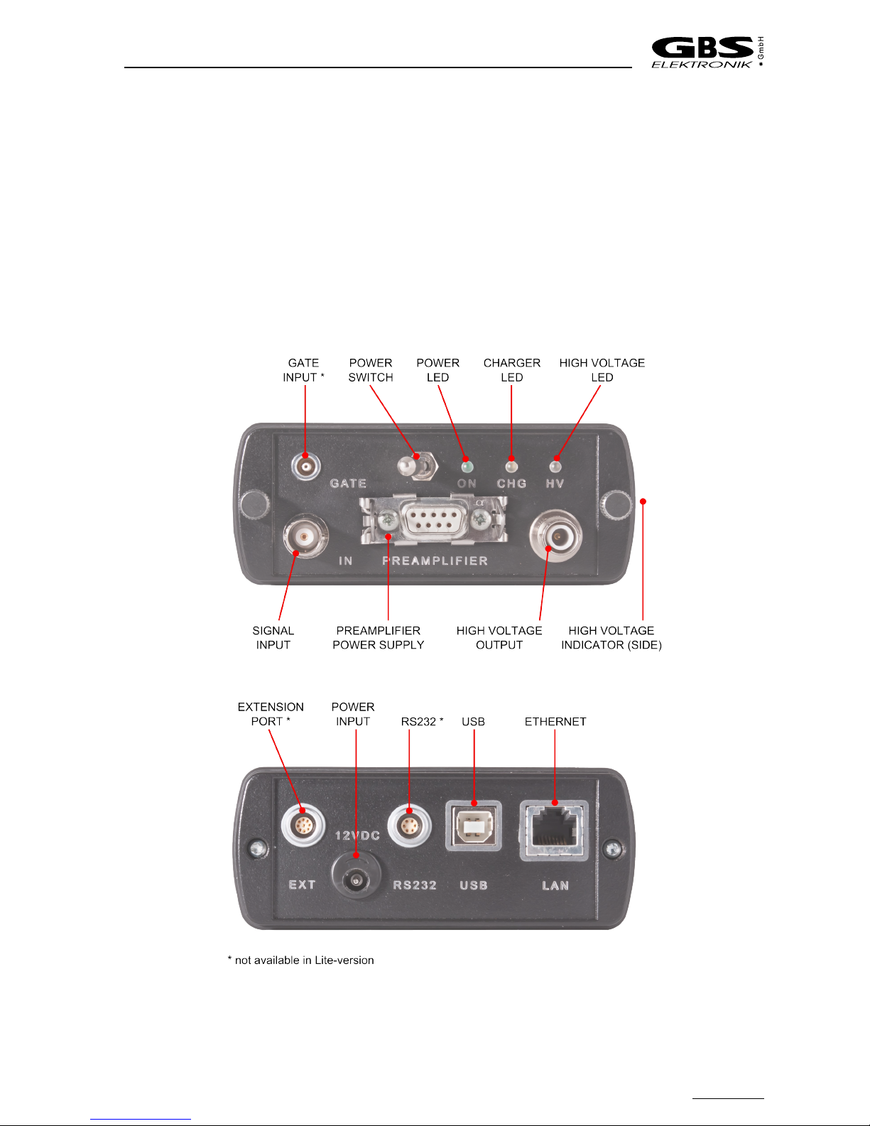
front panel Figure 1 shows the MCA527 front and rear panel with all connectors, control
elements and indicators
9
Figure 1: MCA527 connectors and control elements

MCA527
2.2.1 Switching on the Device
The MCA527 is set into operation by turning on the power switch (Figure 1) After that the
power supply checks the battery voltage and if it is higher than 6 8V it supplies the
complete device with power The main processor boots now and the three LED indicators
flashes some times alternately for about 3 seconds After finishing the boot process the
device enters into the idle state and the green LED flashes symmetrically with 2 5Hz
When a connection to a control program was established the device enters into the
normal state and the green LED flashes symmetrically with 1 25Hz
When the MCA527 is not working but the main switch is still on, the device has turned off
automatically because of a power failure or a loss of battery power If a power failure
occurred, turn off and on again the main switch The device should reboot and enter into
the idle state If the batteries are empty, connect a charger first The yellow LED shines
during charging and when the battery voltage reaches 6 8V the MCA527 turns on
automatically
2.2.2 LED ndicators
The LEDs indicates the actual device state even if no computer is available or located far
away from the MCA All possible states are shown in Figure 2
The green LED shows the device state After turning on, the device enters into the idle
state and only the green LED blinks symmetrically with 2 5Hz When a successful
communication takes place, the MCA enters into the normal state and the green LED
blinks with 1 25Hz until a failure occurs The failure is displayed by asymmetric blinking of
the green LED During a firmware update the green LED shines permanently
When the yellow LED shines it indicates that the internal charger is powered from an
external source (wall adapter or USB port) and charges the batteries This LED shines
even if the MCA is turned off and the batteries are charged
A red/blue bi-color LED displays information about the high voltage If the LED is dark, the
HV is turned off When it flashes red or blue with app 1Hz the high voltage is active and
works properly During the change from one value to another, the HV-LED is permanently
on until the high voltage has reached the new value If a high voltage failure occurs, this
LED blinks red and blue alternately
10

Hardware
2.2.3 Power Management
The MCA527 works with a built in rechargeable Li-Ion battery, which has no memory
effect and is deep discharge and short circuit protected If the device is working, the
remaining battery life time is permanently checked When the battery voltage has dropped
down to 6 8V while a data collection is in progress, the MCA527 gives out a warning to the
user (the lamp will flash irregularly and the software will show an error message) The
running measurement is automatically stopped and the detector high voltage together with
the preamplifier power supply will be switched off
Now the user can transfer the measured spectrum to the computer, but should switch the
device off afterwards or connect an external power source (wall adapter) If the user does
not respond, and the battery life time is nearly used up (battery voltage 6 5V) , the device
switches off automatically It is made sure, that the setup and the spectrum gathered
previously is saved in the memory of the MCA527 permanently
11
Figure 2: LED Indicator blinking scheme
0 0,5 1 1,5 2 t[s]
dle
State
Normal
State
Failure
State
Firmware
Update
Charging
positive
HV on
negative
HV on
positive
HV changes
negative
HV changes
HV Failure
Charging,
Battery full

MCA527
The remaining battery life time is sufficient to transfer the measured spectrum to a
computer It is recommended, before reading out the MCA527, to connect it to an external
power source
In the case that the battery voltage drops below its lowest value, the battery itself switches
off This can be, for example, the result of a lasting short circuit at the preamplifier power
supply As a consequence the internal setup and the measured values are lost The
MCA527 has to be connected to an external charger to recharge the battery
2.2.4 Charging the MCA527
Charging the MCA battery is usually done by connecting the wall adapter to the power
input connector and power it from the mains supply The wall adapter is able to deliver
enough power to operate the MCA527 stationary under a maximum load condition (HV
on, detector draws up to 2W preamplifier power) If the MCA527 is operated on a high
power USB hub and the wall adapter isn’t connected, it can be charged from the USB
port But there is a limitation of 2,5W nominal input power which is the maximum power
that can be drawn from a high power USB port (real usable input power depends on hub
voltage, voltage loss on USB cable and connectors and efficiency of internal charger; it is
usually about 2W) This is enough power to operate the MCA527 without detector or with
a low power detector (e g CdZnTe or NaI) If a detector draws to much power from the
MCA527 (e g some HPGe), charging via USB is still working but the battery runs out
slowly
There are two different variants of behavior when the MCA527 is connected to a working
high power USB hub Each variant has advantages and disadvantages The variant is
hard coded within the MCA527
ariant 1: Charging keeps switched off when the MCA527 is connected to a working high
power USB hub This saves the laptop battery from potential discharge, however, the
MCA battery will be potentially emptied
ariant 2: Charging is started after 6 seconds automatically when the MCA527 is
connected to a working high power USB hub This saves the MCA battery from potential
discharge, however, the laptop battery will be potentially emptied One advantage of this
variant is that a MCA527 that battery is fully discharged can be operated without a wall
adapter
Since the most users prefer the first variant, it is the standard variant It is however
possible to get the second variant on request
It is possible to enable or disable USB charging by newer application programs such as
WinSPEC Connecting the wall adapter to the MCA527 and supply it with power will
always turn off USB charging
The old battery chargers supplied with the MCA166 (3 pin LEMO connector) or
the MCA166-USB (2 pin LEMO connector) are not compatible with the MCA527!
Don’t try to connect them to the MCA527 The connectors are mechanically
different
12

Hardware
With the MCA527 it is possible to use a cheap wall plug supply in emergency cases
However this is not recommended, as cheap supplies have no locking connector, can
make problems with electromagnetic compatibility, there may be supplies with compatible
plug but unsuitable voltage, and even unregulated nominal 12V supplies may have idle
voltages as high as 20V which may destroy the MCA527 So when using an alien power
supply make at least sure that the inner connector is positive and the idle voltage is not
higher than 14V
2.2.5 Exchanging Batteries
The rechargeable batteries of the MCA527 are long lived Li-Ion batteries of the type Sony
NP-F570 or comparable If however it is necessary to exchange the batteries, it is as
simple as exchanging the HV module Proceed as follows:
●Switch off MCA
●Remove both screws on the front panel
●Pull off the front panel Attached to this is the base board with the HV module and
the batteries Pull it fully apart
●Remove old batteries Just pull them off to the side
●Make sure that the new batteries have exactly the same voltage / charge state The
voltage difference must never exceed 0 5V, otherwise there is the danger of battery
destruction
●It is also possible to operate the MCA with only one battery inserted, but then
operation time is reduced to 40% 50% The MCA527L comes with only one
battery inserted
●Afterwards insert the base board in the correct slit, and also be careful with
inserting the upper board plug
●Make sure that the rubber is correctly between housing and front panel and fasten
screws
2.2.6 Connecting the MCA527 to a Computer
Three different communication interfaces are offered by the MCA527 Depending on the
situation each interface has various advantages
The standard RS232 interface is available via a 6 pole Lemo socket Because this is the
same like on the MCA166-USB, the RS232 cable from the MCA166-USB can be used
Three different baud rates are supported by the MCA527, 38 400, 115 200 and 307 200
Baud All newer application programs for the MCA are using always the highest possible
baud rate depending on the computer hardware Because the firmware of the MCA527 is
able to detect the hosts baud rate automatically, usually no manual interface configuration
is necessary
13

MCA527
If the host computer offers an USB host controller, communication can be done via the
USB interface Independent of the application program and the host computer hardware
the used baud rate is always 3MBaud This is nearly ten times faster than the highest
possible RS232 baud rate Another advantage of the USB interface is the possibility to
charge the MCA527 from the USB port USB charging is only possible if the MCA is
connected to a high power USB hub (see also 2 2 4 Charging the MCA527)
The MCA527 has got an Ethernet interface that supports 10/100MBit/s By default it is
configured to obtain the IP address automatically from a DHCP server or if not available,
to use Zero Configuration Networking (also named Automatic Private IP Addressing), but it
is also possible to set a fixed customized IP address For that a special program is
required
Running the MCA527 on a Palmtop computer or Pocket PC is possible in most cases but
needs a special communication cable Please contact GBS - Elektronik (http://www gbs-
elektronik de) for availability For proper wiring see Figure 27: MCA527 Block Diagram on
Page 63
2.2.7 Connecting Detectors
Before connecting a detector switch off the device and make sure that the built
in high voltage power supply has the correct polarity and that the power
consumption of the detector does not exceed the maximum ratings of the high
voltage power supply module (0.5mA or 0.25 Watt).
Checking the high voltage modules polarity is simply possible by viewing inside the MCA
through the small hole on the right side of the MCA527 (see Figure 1) If it shines red a
positive HV module is inserted, if it shines blue a negative HV module is present If the
indicator is black / dark gray no HV module is present Furthermore it is possible to check
the HV polarity by software; go to the menu setup / high voltage2 and look for the HV
polarity The correct values for HV, polarity, and power consumption should be found in
the detectors manual
●Check the detector manual for MCA527 compatible pin assignment of the
preamplifier power supply connector and that the power consumption does not
exceed the maximum ratings (see chapter 8 1 2)
●Connect the detectors preamplifier power supply cable to the corresponding female
D-SUB9 socket on the MCA527 and attach it by the clamps
●Connect the detectors BNC Signal cable to the MCA's BNC input connector
●Connect the detectors high voltage cable to the MCA's SHV connector
If problems occur, it is possible to check the detector signal with a scope or in the scope
mode of WinSPEC-A A typical signal which should be seen is shown in Figures 3 and 26
2 available in most application programs, e g WinSPEC and WinSCAN
14

Hardware
15
Figure 3: Typical signal which can be seen at a detector preamplifier output, here from a
CZT500 detector. For optimum performance, the rise time should be in the
order of 100ns, and decay time constant of 50µs. This is drop to 36.8% of peak
value within 50µs or drop to half value within 34.6µs.
MCA527
2.2.8 Applying High Voltage
Most gamma detectors require some high voltage (HV) supply The MCA527 is able to
provide this However, mistakes with the high voltage can seriously damage detectors,
therefore some caution is recommended
●Before applying HV make sure that detector is properly connected
●Check that the polarity of HV module inserted is correct for connected detector
●Do apply the correct voltage for the detector
●Do not plug or unplug HV cables while HV is on
●In case of a HPGe detector, make sure that the detector is fully cooled down for a
few hours
There are also some specific properties for different detector families which are discussed
below
Scintillation Detectors as NaI, LaBr, etc.
For scintillation detectors, the HV is needed for the operation of the photomultiplier The
photomultiplier acts as some kind of amplifier whose amplification is strongly dependent
on the high voltage setting Therefore, it is necessary that this voltage is very stable
However, here the HV can also be used to adjust the gain and optimize performance A
rule of thumb is that the preamplifier output signals should be in the order of 0 5V…1V If
HV is too high, non-linearities of the photomultiplier may become significant in the
spectrum, whereas with too low HV signals become small and noise may become
significant and degrade the resolution Scintillation detector manufacturers tend to give
slightly higher than optimum values for high voltage in their data sheets
16
Figure 4: Dependence of peak position and resolution on high voltage, using a NaI
detector
300 400 500 600 700 800
10
100
1000
6
6,5
7
7,5
Centroid [Ch]
FWHM [%]
Photomultiplier Voltage [V]
Centroid [Ch]
FWHM [%]

Hardware
Hig Purity Germanium (HPGe) Detectors
A HPGe detector is basically a huge cooled high voltage germanium diode with a big
radiation sensitive depletion region In first order, the output does not depend on HV
setting as long as the voltage is above a certain voltage and the detector is fully depleted
Below that value, the resolution degrades, the sensitivity decreases and the signals get
smaller
This is important when dealing with detectors whose HV rating (e g 4500V) is above the
3600V the MCA527 can supply3 If the 3600V is still above the depletion point, it is no
problem to use this detector with lower voltage However, it is not possible to estimate the
depletion voltage from the detector nominal voltage; this has to be found out
experimentally
3 In conjunction with a HV3600 high voltage module
17
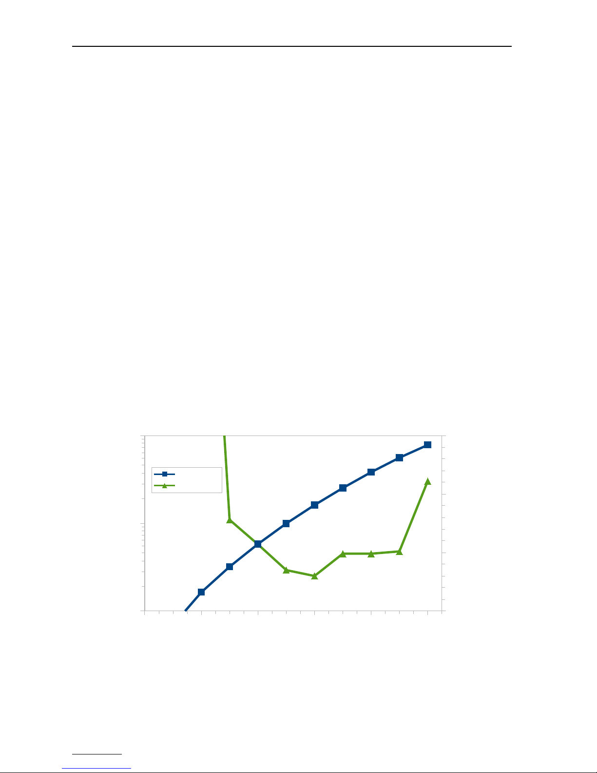
Figure 5: Typical dependence of FWHM, Centroid position and counting rate on H
setting. Peaks at 59 ke and 661 ke are used for evaluation. The nominal
rating of this detector is 2500 , the depletion point is at 1250 .
0 500 1000 1500 2000 2500
0
500
1000
1500
2000
2500
3000
3500
4000
4500
5000
0,5
0,6
0,7
0,8
0,9
1,0
1,1
1,2
FWHM 661 [eV]
FWHM 59 [eV]
Centroid 661 [rel]
Centroid 59 [rel]
Area 661 [rel]
Area 59 [rel]
Detector Bias Supply [V]
FWHM [eV]
rel

MCA527
Most important when applying HV to a HPGe is that the detector must be cooled down
properly and must not become warm while HV is on As this is a mistake which easily
destroys expensive HPGe detectors, most HPGe have a HV inhibit out which becomes
active if the detector gets warm The HV inhibit input for the MCA527 is Pin 5 of the
D-SUB9 preamplifier power connector (see chapter 2 2 12, Preamplifier Power Supply
Connector) As some HPGe have the HV inhibit out on a separate BNC cable, a
corresponding adapter is optionally available
Table 1: H -Inhibit Signal
HV- nhibit mode4Detector inhibit
output voltage,
inhibit active
nhibit voltage,
detector cold
MCA527 condition
to switch HV off
off -
BSI, DFG, Canberra 0V +12V VPIN5 < 0 5V
Ortec +5V 0V VPIN5 > 0 5V
The voltage with connector open at the HV inhibit input of MCA527 is around 2 2V So for
HV inhibit to work properly with Canberra detectors, it must be made sure that the inhibit
is really connected For Ortec detectors, unconnected HV is similar to detector warm, so
there is no problem This behavior is opposite to MCA166, which interprets open input as
0V
Room Temperature Semiconductor Detectors
Room temperature semiconductor detectors (CZT) behave somehow similar to HPGe,
Centroid position depends rather weak on HV setting Choosing a too low voltage effects
that charge loss processes become more dominant and therefore the peaks more
asymmetric With a too high voltage, leakage currents become a problem which cause
additional noise and therefore peak broadening Best is to stay with the rated voltage
2.2.9 Exchanging the High Voltage Module
Switching from positive HV to negative HV can only be done manually by exchanging the
HV module Proceed similar as described in chapter 2 2 5 Exchanging Batteries When
inserting the HV module be careful to insert all pins properly and not to bend or break off
pins
2.2.10 Functions of the D-SUB9 connector
Different functions are available on the MCA527 D-SUB9 connector which are useful with
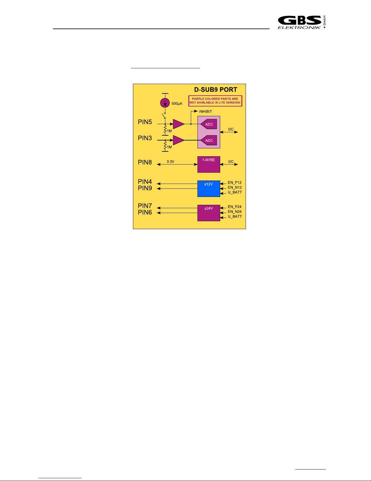
various detectors Figure 6 shows the block diagram The MCA527OEM has not
implemented this functions and the MCA527L only supports the ±12V supply The pin
diagram of the D-SUB9 connector is shown in Table 3
Traditionally this port is used to provide the supply voltages for the detectors preamplifier
The MCA527 delivers ±12V and ±24V while the MCA527L delivers only ±12V Each
voltage can be loaded with up to 60mA Furthermore the MCA527 has some additional
features Some HPGe detectors provides a HV inhibit signal which indicates that the
4 see Windows DLL description
18
Hardware
detector gets warm an the HV must be turned off The MCA527 is able to interpret this
signal for different detectors if it is routed to pin 5 of the D-SUB9 connector A BNC
adapter is available from GBS - Elektronik GmbH For more information see chapter 2 2 8,
Applying High Voltage
Some NaI-detectors are equipped with a 1-wire temperature sensor If the sensors is
connected to pin 8 of the D-SUB9 connector, the MCA527 is able to read out the detectors
temperature and displays it in the diagnostics menu Currently only the DS1822 sensor is
supported by the firmware but in principle every 1-wire device which operates at 3 3V can
be used on the MCA527
Other NaI-detectors have an integrated thermistor for measuring the crystals temperature
The resistance of this sensor can be measured with the MCA527 on Pin 5 of the D-SUB9
connector By turning on the internal current source a constant current of about 500µA is
fed into the thermistor and the resulting voltage is measured with the ADC on pin 5 (see
Figure 6) The application program calculates the corresponding resistance and
temperature with respect to the input impedance and displays it in the diagnostics menu
Because the current source has a relative large tolerance, its real value is measured
during production and stored inside the MCA This parameter is used for calculating the
resistance Resistors up to 8kW can be measured
If the current source is turned off, pin 5 of the D-SUB9 connector can be used as general
purpose analog input like pin 3 too Both inputs accepts voltages between 0V an 10V and
are sampled nearly every second with a resolution of 11bit The voltages are displayed in
the diagnostics menu
19
Figure 6: Block diagram of all components connected to the D-SUB9 connector. Only the
MCA527 supports all functions, the MCA527L is only populated with the ±12
preamplifier power supply.
MCA527
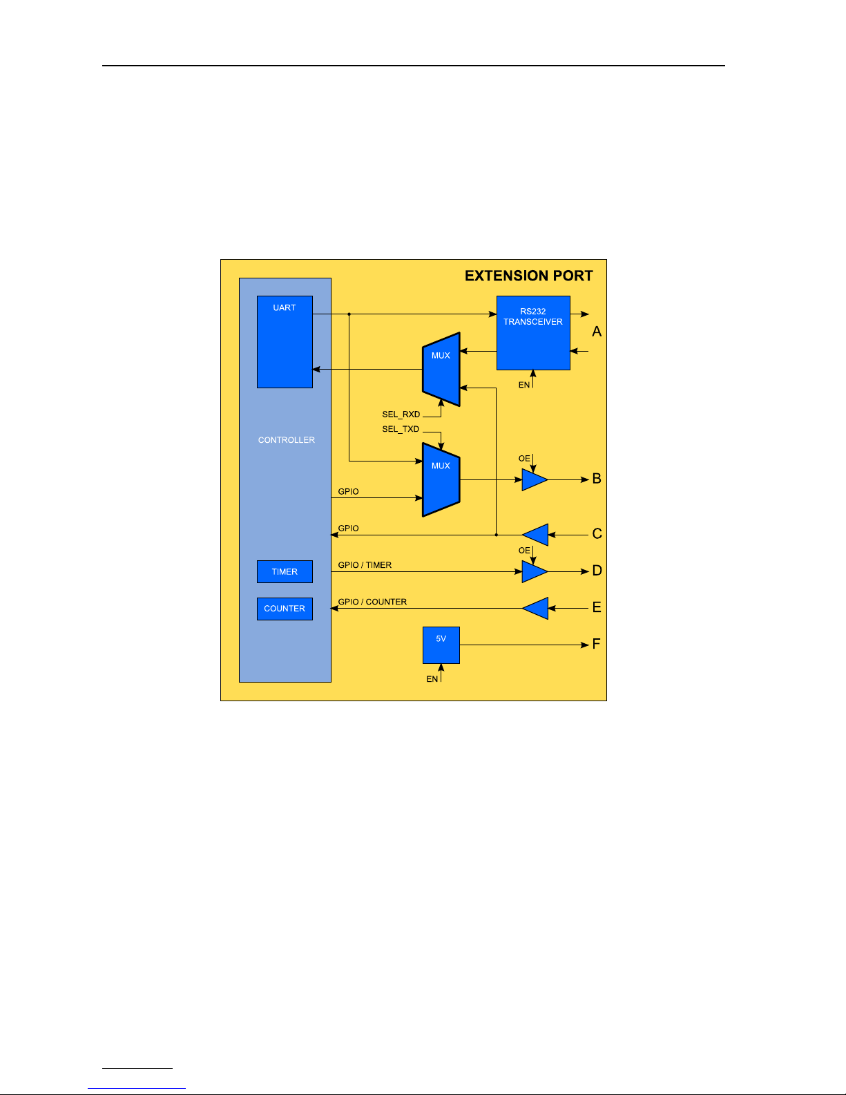
2.2.11 Extension Port
The extension port is only available on the MCA527, the MCA527L and the MCA527OEM
are not equipped with this functionality This port extends the possibilities of the MCA
enormously Different external devices, such as GPS receivers or neutron counters, can
be attached to the MCA527 by a 9 pin Lemo connector (Table 6) Figure 7 shows the
block diagram Currently the basic functionality is implemented in the firmware but no
application program takes advantage of it
The extension port consist of six independent parts labeled A to F Part A is a true RS232
interface which can operate at speeds up to 1MBaud To save power, the transceiver is
disabled by default Part B is a 3 3V digital output with output enable It can be used as
general purpose output or as TTL-UART TxD Part C is a 3 3V digital input which is 5V
tolerant It can be used as general purpose input or as TTL-UART RxD The TTL-UART
can be operated at speeds up to 3MBaud Part D is an additional 3 3V digital output with
output enable It can be used as general purpose output or as timer output for pulse
generation Part E is a further 5V tolerant 3 3V digital input which can be used as general
purpose input or as fast counter To supply external devices with power, a 5V converter is
also part of the extension port (F) It can be loaded with up to 100mA To save power, it is
disabled by default
20
Figure 7: Block diagram of the extension port. This functions are only supported by the
MCA527.
Table of contents
Other GBS Elektronik Measuring Instrument manuals

Popular Measuring Instrument manuals by other brands

Moore & Wright
Moore & Wright 150 Series instructions

BRONKHORST
BRONKHORST MASS-STREAM D-6200 instruction manual

STS Instruments
STS Instruments Siloxane installation manual

Velleman
Velleman WS8461 user manual

ATN
ATN LaserBallistics 1000 owner's manual

Helios
Helios CO2 AP-A Installation and operating instructions

Extech Instruments
Extech Instruments DC400 user guide

Hytek
Hytek HO Series Technical data

SIGLENT TECHNOLOGIES
SIGLENT TECHNOLOGIES SSA3000X Plus user manual

Tektronix
Tektronix DSA8200 Series instructions

TQC
TQC Super Pig III SP1100 user guide

Agilent Technologies
Agilent Technologies TapeStation 4200 Software & User Information


