gc MICROGUARD TEREX RCI 510/400 Manual

GREER COMPANY
Crane Systems
GREER COMPANY 1918 East Glenwood Place, Santa Ana, CA 92705 TEL: (714) 259-9702 FAX: (714) 259-7626
MicroGuard® RCI 510/400 CALIBRATION MANUAL PN W450189A 09/09/02
1 of 65
MICROGUARD
TEREX RCI 510/400 SYSTEM
TELESCOPIC BOOM CRANE
CALIBRATION PROCEDURE
ORs Full 9.7Klb Ctwt
ERECTED 60' TELEJIB 17 AUXHD ON
PICK FROM MAIN BOOM FRONT WINCH
TEST
MAX
SET
360
o
6
23,500
i2,300
44.8
62.7
26.4
o
Rated Capacity
Actual Load
Length
Main Boom
Angle
Main Boom
Load Radius
Parts
of
Line
Display Screen

GREER COMPANY
Crane Systems
GREER COMPANY 1918 East Glenwood Place, Santa Ana, CA 92705 TEL: (714) 259-9702 FAX: (714) 259-7626
MicroGuard® RCI 500 CALIBRATION PROCEDURE PN W450189A 09/09/02
2 of 65
MICROGUARDTEREX RCI 510/400 SYSTEM
TELESCOPIC BOOM CRANE
CONTENTS
PRE-CALIBRATION REQUIREMENTS ..................................................................................................... 4
OVERVIEW.............................................................................................................................................. 4-5
THE CAL SWITCH...................................................................................................................................... 5
ENTERING THE CALIBRATION MODE .................................................................................................... 6
ENTERING THE CALIBRATION SECURITY CODE ......................................................................... 6
USING THE DISPLAY KEYS IN COMMAND ROUTINES ......................................................................... 7
COMMAND 00 RUN ................................................................................................................................... 8
COMMAND 01 PERSONALITY................................................................................................................ 9
COMMAND 01/2 INITIALIZE .................................................................................................................... 10
COMMAND 01/0 SAVE............................................................................................................................. 11
COMMAND 02 TEST/FAULT ..............................................................................................................12-13
NUMBER ENTRY ..................................................................................................................................... 14
COMMAND 03 ZERO ............................................................................................................................... 15
ZERO PRESSURE TRANSDUCERS..........................................................................................16-17
ZERO EXTENSION SENSOR .....................................................................................................18-19
ZERO BOOM ANGLE SENSOR..................................................................................................20-21
COMMAND 04 SPAN ............................................................................................................................... 22
BOOM ANGLE SENSOR.............................................................................................................22-23
EXTENSION SENSOR ..................................................................................................................... 24
COMMAND 05 SWING............................................................................................................................. 25
SCALE .............................................................................................................................................. 26
ZERO ................................................................................................................................................ 27
DIRECTION ...................................................................................................................................... 28
CONFIGURATION SELECTION .........................................................................................................29-33

GREER COMPANY
Crane Systems
GREER COMPANY 1918 East Glenwood Place, Santa Ana, CA 92705 TEL: (714) 259-9702 FAX: (714) 259-7626
MicroGuard® RCI 510/400 CALIBRATION MANUAL PN W450189A 09/09/02
3 of 65
COMMAND 06 PRESSURE ................................................................................................................34-36
COMMAND 07 RADIUS/MOMENT – MAIN BOOM ............................................................................37-41
RADIUS MOMENT – MAIN BOOM + MANUAL .......................................................................... 42-45
COMMAND 08 BOOM DEFLECTION CORRECTION............................................................................. 46
COMMAND 09 ANNULAR GAIN .............................................................................................................. 47
COMMAND 12 WINCHES ........................................................................................................................ 48
COMMAND 13 ATTACHMENTS .............................................................................................................. 48
COMMAND 14 BOOM HEAD .............................................................................................................. 49-50
COMMAND 15 ALARM LIMITS ........................................................................................................... 51-53
COMMAND 16 ROPE DATA ............................................................................................................... 54-56
COMMAND 17 AMPLIFIER GAIN ............................................................................................................ 57
COMMAND 01 BACKUP .......................................................................................................................... 57
SWITCH OFF POWER TO THE SYSTEM............................................................................................... 58
COMMAND 01/4 RESTORE..................................................................................................................... 58
COMMAND 19 DIGITAL INPUTS............................................................................................................. 59
GLOSSARY ......................................................................................................................................... 60-64

GREER COMPANY
Crane Systems
GREER COMPANY 1918 East Glenwood Place, Santa Ana, CA 92705 TEL: (714) 259-9702 FAX: (714) 259-7626
MicroGuard® RCI 510/400 CALIBRATION MANUAL PN W450189A 09/09/02
4 of 65
MICROGUARDTEREX RCI 510/400 SYSTEM
TELESCOPIC BOOM CRANE
PRE-CALIBRATION REQUIREMENTS
Following satisfactory installation of the complete RCI 510/400 System:
♦ Ensure that the system is wired in accordance with the appropriate wiring diagram,
which is available upon request from Greer.
♦ Ensure that the crane is on firm and level ground, that the outrigger beams are fully
extended, and that the jacks are correctly extended to level the carrier.
♦ Ensure that throughout the procedure any structural or stability limits are not exceeded.
♦ Ensure that any attachments (aux. head, fly, jib, etc.) that can be optionally stowed or
erected on the boom during normal operation are removed prior to calibration of the
main boom.
♦ Ensure that the computer is fitted with the program and duty chips specified in the
installation manual.
Using the RCI 510/400 System display, proceed with the calibration commands, as directed in
this manual.
OVERVIEW
When accurately calibrated, this System provides the operator with a continuous display of the
following:
♦ Rated Load
♦ Actual Load
♦ Bar Graph showing Percentage of Rated Load
♦ Radius of the Load
♦ Boom Angle
♦ Main Boom Length
♦ Working Area
♦ Crane Configuration
The RCI 510/400 Display shown on the cover of this manual identifies where this data will
appear.
Messages on the display screen provide the operator with visual warnings of conditions that
occur during operation of the system.
THIS MANUAL PROVIDES STEP-BY-STEP DIRECTIONS FOR EACH COMMAND USED IN THE
CALIBRATION OF THE RCI 510/400 SYSTEMS.
GREER COMPANY
Crane Systems
GREER COMPANY 1918 East Glenwood Place, Santa Ana, CA 92705 TEL: (714) 259-9702 FAX: (714) 259-7626
MicroGuard® RCI 510/400 CALIBRATION MANUAL PN W450189A 09/09/02
5 of 65
OVERVIEW continued
WARNI NG
!
When the system is in the Calibration Mode,
the audible alarm and function kick-outs are
inhibited and there is no protection from two-
block or overload. All crane operations are at
the sole discretion of the operator.
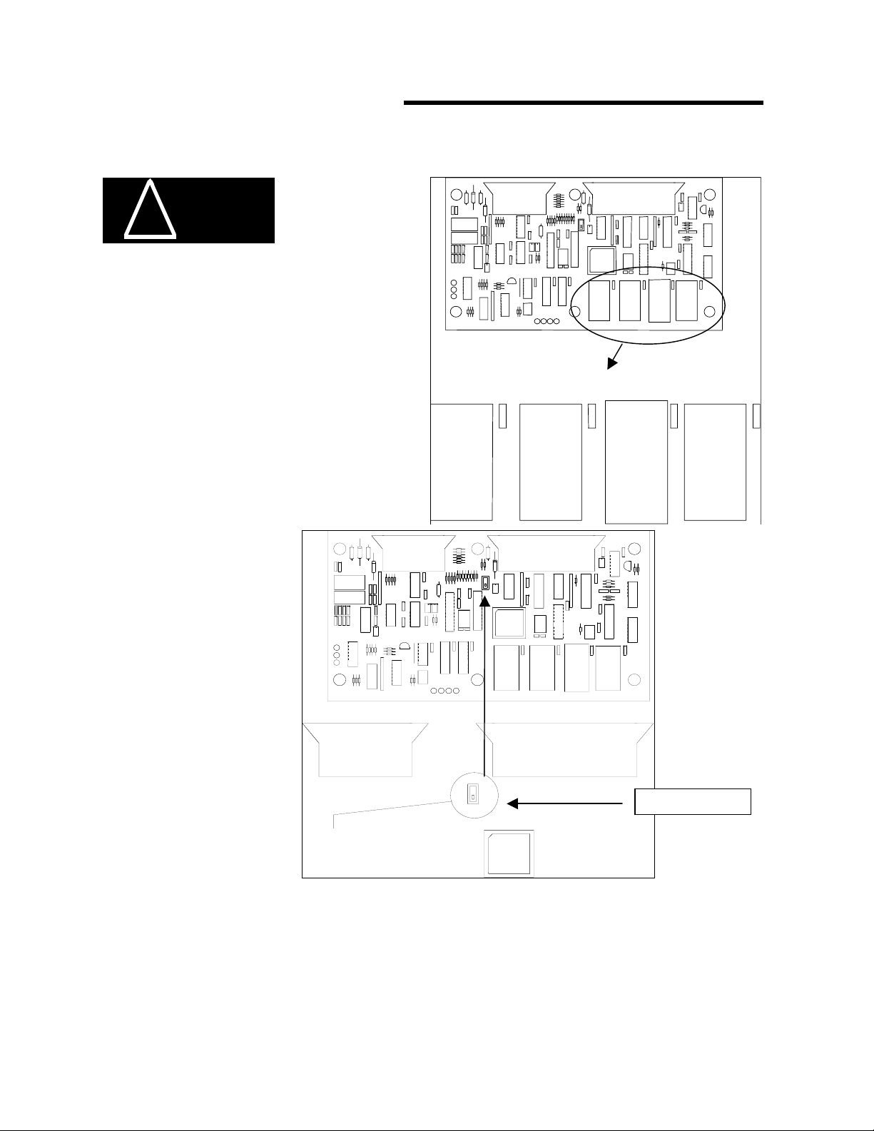
THE CAL SWITCH
CAL SWITCH
PROGRAM
CHIP
DUTY
CHIP
PERSONALITY
CHIP
IC2 IC3 IC7
CAL POSITION
The CAL switch in the
computer must be set to the
“CAL” POSITION when
performing
calibration procedures.
To access the CAL switch,
REMOVE the cover from
the computer assembly.
Locate the switch near the
center of the computer
board just between and
below the ribbon cable
connectors.
IMPORTANT: IF THE CALIBRATION SWITCH IS NOT ON (PULLED DOWN OR FORWARD) THE
DISPLAY SHOULD READ: ‘CAL DISABLED’ AND THE ROUTINES CANNOT BE ACCESSED.
GREER COMPANY
Crane Systems
GREER COMPANY 1918 East Glenwood Place, Santa Ana, CA 92705 TEL: (714) 259-9702 FAX: (714) 259-7626
MicroGuard® RCI 510/400 CALIBRATION MANUAL PN W450189A 09/09/02
6 of 65
ENTERING THE CALIBRATION MODE
To perform any calibration routine, the System must operate in the “Calibration Mode.” To
access the Calibration Mode, press the Test and Set keys simultaneously for approximately
two seconds.
ENTERING THE CALIBRATION SECURITY CODE
Entry of the Calibration Security Code will be required often throughout these procedures.
Press keys 1 2 3 4 below in this sequence to enter the Calibration Security
Code. If the wrong sequence is used or if the entry is not completed within 5 seconds, the entry
will be aborted and must be entered again. This code will be used often throughout these
routines. It is helpful to memorize these key positions.
ORs Full 9.7Klb Ctwt
ERECTED 60' TELEJIB 17 AUXHD ON
PICK FROM MAIN BOOM FRONT WINCH
TEST
MAX
SET
360
o
6
23,500
i2,300
44.8
62.7
26.4
o
3 2 4
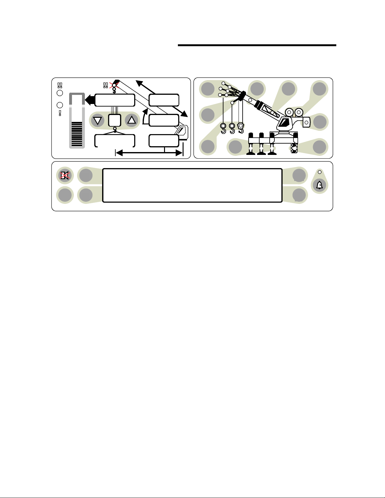
1 THE RCI 510/400 DISPLAY
GREER COMPANY
Crane Systems
GREER COMPANY 1918 East Glenwood Place, Santa Ana, CA 92705 TEL: (714) 259-9702 FAX: (714) 259-7626
MicroGuard® RCI 510/400 CALIBRATION MANUAL PN W450189A 09/09/02
7 of 65
USING THE DISPLAY KEYS IN COMMAND ROUTINES
During the calibration routines, the A B C D display keys are used to enter data.
When entering the Calibration Security Code, use the 1234 format shown on page 6.
PRESS Ato scroll forward to a command or option, to enter a current selection into
the system, etc.
PRESS Bto scroll backward to an option or command, etc.
PRESS Cto start a command, to confirm an entry, to calibrate, or to respond to
screen questions, etc.
PRESS Dto exit a routine or abort a calibration.
Follow directions in each command carefully. To enter numbers other than the security code,
use the number entry procedure.
If the display reads: “system out of service,” simultaneously press the “Test“ and “Hold“keys
for a few seconds. The display will request entry of the calibration security code. Following
entry of the correct code, the user will be returned to the calibration mode.
When using the number entry routine, always press Cbefore exiting the routine to enter the
data into the system.
Display scrolling keys (Aand B) can be moved full circle allowing all options listed to be
viewed when moving in either direction.
The term “repeat last entry” is an option not a request. It allows the operator to repeat
entered information if a mistake is made.
ORs Full 9.7Klb Ctwt
ERECTED 60' TELEJIB 17 AUXHD ON
PICK FROM MAIN BOOM FRONT WINCH
TEST
MAX
SET
360
o
6
23,500
i2,300
44.8
62.7
26.4
oC
D
B
A
THE RCI 510/400 DISPLAY

GREER COMPANY
Crane Systems
GREER COMPANY 1918 East Glenwood Place, Santa Ana, CA 92705 TEL: (714) 259-9702 FAX: (714) 259-7626
MicroGuard® RCI 510/400 CALIBRATION MANUAL PN W450189A 09/09/02
8 of 65
COMMAND 00 RUN
After accessing the Calibration Mode and entering the Calibration Security
Code (see page 6),the system will be in the “Monitor Mode” at Command 00 Run.
Do not execute this Command when preparing to calibrate the system; to do so will
cause the system to carry out a “system test” followed by a return to the working screen.
Press “A” (menu up) or “B” (menu down) to view all commands. See the illustration on page 7.
Stop at Command 01 Personality.

GREER COMPANY
Crane Systems
GREER COMPANY 1918 East Glenwood Place, Santa Ana, CA 92705 TEL: (714) 259-9702 FAX: (714) 259-7626
MicroGuard® RCI 510/400 CALIBRATION MANUAL PN W450189A 09/09/02
9 of 65
WARNI NG
!
WARNI NG
!
COMMAND 01 PERSONALITY
Command 01 Personality is used to manipulate the crane calibration data.
The system stores two sets of data in EEPROM IC7.
“A“ Active Personality (IC7) –contains the data actually used by the main program.
“B“ Backup Personality (IC7) –contains a “protected” copy of the calibration data.
COMMAND 01 FUNCTION
♦DISPLAYS THE STATUS OF THE PERSONALITY SETS.
♦MOVES DATA BETWEEN THE TWO SETS.
♦DELETES DATA FROM THE ACTIVE PERSONALITY.
♦COPIES DATA TO A BACK-UP CHIP.
♦RETRIEVES DATA FROM A BACK-UP CHIP.
When the command is first selected (after copying data), both “A” and “B” sets are checked for
correct Check-Sum. This is indicated on the display screen by “Good” or “Bad.”
Set “A” is also checked against set “B.” Data that is identical is indicated by “Same” or if not the
same, by “Diff.”
Data can be moved using selected sub-commands and the calibration
security code. Data entered may also be aborted before completion of the
routine. Special care must be taken when working with the sub-commands
as some of the sub-commands can cause previously entered data to be
irretrievably lost.
SUB-COMMAND 01/0 SAVE SAVES “A” INTO “B” (“B“DATA IS LOST).
SUB-COMMAND 01/1 XCHG EXCHANGES “A” WITH “B” (DATA IS NOT LOST).
SUB-COMMAND 01/2 INIT INITIALIZES “A” PRIOR TO NEW CALIBRATION (“A“DATA IS
LOST).
SUB-COMMAND 01/3 BACK COPIES THE ACTIVE CALIBRATION TO A BACK-UP CHIP
(DATA IS NOT LOST).
SUB-COMMAND 01/4 RETR RETRIEVES THE CALIBRATION FROM A BACK-UP CHIP
(PREVIOUS “A“DATA IS LOST).
Power to the system should be switched off before inserting or removing
any integrated circuits. Failure to observe this precaution may cause
permanent damage to the system or its components and result in the loss of calibration data.
GREER COMPANY
Crane Systems
GREER COMPANY 1918 East Glenwood Place, Santa Ana, CA 92705 TEL: (714) 259-9702 FAX: (714) 259-7626
MicroGuard® RCI 510/400 CALIBRATION MANUAL PN W450189A 09/09/02
10 of 65
WARNI NG
!
COMMAND 01/2 INITIALIZE
Command 01/2 is used only when calibrating the System for the first
time. The use of this command causes all previously entered “A” side
calibration data to be erased. If the system has been previously calibrated
and data from a previous calibration is to be accessed or changed, proceed directly to the
command to be changed. Do not perform the initialization command below.
COMMAND 01/2 INITIALIZE ROUTINE
This Procedure Completely Erases All Previous Data From “A” Personality.
To cancel this routine, PRESS D, ABORT before completing Step 5.
1) PRESS A TO 01 PERSONALITY.
2) PRESS C TO START THE COMMAND.
3) PRESS A TO 2 INIT PERS A ONLY.
4) PRESS C TO START THE CALIBRATION.
5) PRESS C TO CALIBRATE OR PRESS D TO ABORT THE CALIBRATION.
6) PRESS 1234 (CALIBRATION SECURITY CODE)
AFTER THE MESSAGE, “CALIBRATING” ENDS, THE DISPLAY SHOULD READ:
“AGOOD BGOOD SAME“(See page 6).
7) PRESS D TO EXIT ROUTINE. THE SYSTEM WILL RETURN TO THE MONITOR MODE BUT
WILL REMAIN IN THE CALIBRATION ROUTINE.
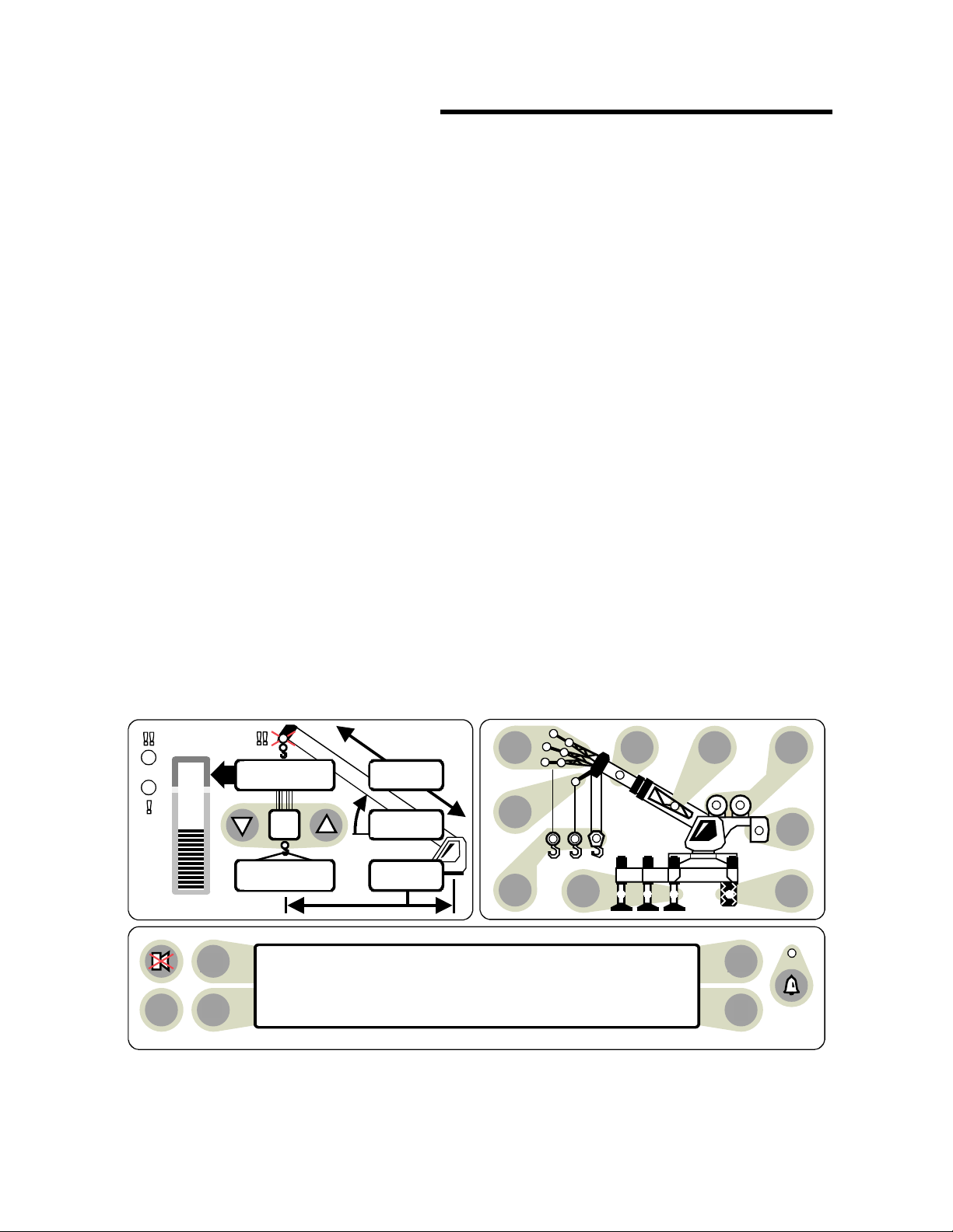
2 Init Pers A Only
ORs Full 9.7Klb Ctwt
ERECTED 60' TELEJIB 17 AUXHD ON
PICK FROM MAIN BOOM FRONT WINCH
TEST
MAX
SET
360
o
6
23,500
i2,300
44.8
62.7
26.4
oC
D
B
A 01 Personality

GREER COMPANY
Crane Systems
GREER COMPANY 1918 East Glenwood Place, Santa Ana, CA 92705 TEL: (714) 259-9702 FAX: (714) 259-7626
MicroGuard® RCI 510/400 CALIBRATION MANUAL PN W450189A 09/09/02
11 of 65
COMMAND 01/0 SAVE
• If calibrating the entire system, execute Command 01/0 Save after completing
each calibration routine to ensure that a complete copy of the calibration data is entered in
the backup memory of the system.
• If modifying or correcting an existing calibration, do not save until satisfied with
the results of the calibration.
This Command can be used at any time to ensure that data entered up to the time that
this routine is completed will be saved in the system.
COMMAND 01/0 SAVE ROUTINE
(applicable to all calibration routines in this manual)
1) PRESS ATO 01 PERSONALITY.
2) PRESS CTO START THE COMMAND.
3) PRESS A TO 01/0 SAVE.
4) PRESS CTO START THE CALIBRATION.
5) PRESS CTO CALIBRATE OR PRESS D TO ABORT THE CALIBRATION.
6) PRESS 1234 (SECURITY CODE).
7) AFTER MESSAGE, “CALIBRATING” ENDS, PRESS D TO EXIT THE ROUTINE.

GREER COMPANY
Crane Systems
GREER COMPANY 1918 East Glenwood Place, Santa Ana, CA 92705 TEL: (714) 259-9702 FAX: (714) 259-7626
MicroGuard® RCI 510/400 CALIBRATION MANUAL PN W450189A 09/09/02
12 of 65
COMMAND 02 TEST/FAULT
Command 02 activates a System “Self-Test” to detect and display errors (faults) in the system.
1) PRESS ATO 02 TEST/FAULT.
2) PRESS C TO EXECUTE A SYSTEM SELF-TEST AND TO DISPLAY ERRORS.
3) PRESS D TO EXIT THE ROUTINE.
FAULTS
GROUP “A“ANALOG SENSORS
CODE
AAA
000 NO FAULTS
001 SENSOR 0 PISTON PRESSURE TRANSDUCER
002 SENSOR 1 ROD SIDE PRESSURE TRANSDUCER
004 SENSOR 2 EXTENSION SENSOR
008 SENSOR 3 BOOM ANGLE SENSOR
016 SENSOR 4 S’STRUCTURE ANGLE SENSOR
032 SENSOR 5 SWING POTENTIOMETER "A"
064 SENSOR 6 SWING POTENTIOMETER "B"
GROUP "B" INPUTS AND OUTPUTS
CODE
BB
00 NO FAULTS
01 FAULT 1 DIGITAL INPUT AND OUTPUT
02 FAULT 2 ANALOG INPUT AND OUTPUT
04 FAULT 4 DISPLAY UNIT

GREER COMPANY
Crane Systems
GREER COMPANY 1918 East Glenwood Place, Santa Ana, CA 92705 TEL: (714) 259-9702 FAX: (714) 259-7626
MicroGuard® RCI 510/400 CALIBRATION MANUAL PN W450189A 09/09/02
13 of 65
GROUP “C“MEMORY
CODE
CC
00 NO FAULTS
01 FAULT 1 EXECUTIVE ROM
02 FAULT 2 DUTY ROM
04 FAULT 4 SCRATCHPAD RAM
08 FAULT 8 PERSONALITY ROM
GROUP “D“GENERAL
CODE
DD
00 NO FAULTS
01 FAULT 1 NO DUTY FOUND
02 FAULT 2 CURRENT DUTY BAD
04 FAULT 4 ROPE OR RAM DIMENSION MISSING
08 FAULT 8 FLY NOT CALIBRATED

GREER COMPANY
Crane Systems
GREER COMPANY 1918 East Glenwood Place, Santa Ana, CA 92705 TEL: (714) 259-9702 FAX: (714) 259-7626
MicroGuard® RCI 510/400 CALIBRATION MANUAL PN W450189A 09/09/02
14 of 65
NUMBER ENTRY
The MicroguardRCI 500 does not have number entry keys. When numerical entry of data is
required, the display will change to allow the entry of numbers.
• A strip like the one below will appear with numerals from 0 to 9 followed by the three
symbols shown.
• The upper left corner identifies the Command (in this case, 06 Pressure). The upper
right displays each numeral as entered until the complete number to be calibrated
appears, including decimals and minus sign.
• The keys operate as in the calibration routines (A B C D).
1) When the number entry panal appears, the selectors < > will surround the zero < 0 >
numeral which will be flashing. Use “key B” or “key D” to select a numeral. If key B is
pressed, the cursor will jump to the opposite end of the display panel and the selectors
will surround the minus sign. With each press of key B the cursor will backtrack by one
digit toward the original site 0 (zero). When key D is used, the identical process occurs
in reverse.
2) When not at the starting point (“0“or “-“), pressing key B or key D will cause the
cursor to move one digit at a time toward its original site. Example:if the cursor were
flashing at numeral 5, pressing key B once would cause the cursor to move one digit
toward 0(zero).
3) WHEN ENTERING A MINUS SIGN FOR A NEGATIVE VALUE, ALWAYS DO SO
AFTER ALL NUMERALS HAVE BEEN SELECTED.
4) As each digit is selected, press key A to enter it into the system. The
numeral will then appear in the upper right bracket. Continue entering numerals and
decimal point, as appropriate, until the complete number appears in the upper right box.
A total of five digits may be entered in this way.
5) If an error is made when entering a numeral, immediately select the “less than” symbol
(<) and press key A. The number should be removed from the right upper selection
box. Numbers can be removed this way one digit at a time.
6) When all digits look correct, press key C to calibrate the complete number.
06 Pressure ( 1.0 )
Calibration Load
0 1 2 3 4 5 6 7 8 9 <<·> -

GREER COMPANY
Crane Systems
GREER COMPANY 1918 East Glenwood Place, Santa Ana, CA 92705 TEL: (714) 259-9702 FAX: (714) 259-7626
MicroGuard® RCI 510/400 CALIBRATION MANUAL PN W450189A 09/09/02
15 of 65
COMMAND 03 ZERO
Command 03 Zero permits calibration to zero for most analog sensors, including the four
system sensors shown below. Each sensor is allocated a number corresponding to the input
connection in the system.
♦PISTON SIDE PRESSURE TRANSDUCER INPUT TX. 0
♦ROD SIDE PRESSURE TRANSDUCER INPUT TX. 1
♦BOOM EXTENSION SENSOR ANALOG INPUT 2
♦BOOM ANGLE SENSOR ANALOG INPUT 3
DURING COMMAND 03 ZERO ROUTINES, THE BOOM MUST ALWAYS BE IN A
HORIZONTAL POSITION.
COMMAND 05 IS USED TO CALIBRATE THE SWING SENSOR.
Continue with the Command 03 Zero calibration routines on the following pages.

GREER COMPANY
Crane Systems
GREER COMPANY 1918 East Glenwood Place, Santa Ana, CA 92705 TEL: (714) 259-9702 FAX: (714) 259-7626
MicroGuard® RCI 510/400 CALIBRATION MANUAL PN W450189A 09/09/02
16 of 65
COMMAND 03 ZERO - PRESSURE TRANSDUCERS
♦Lower the boom until its lower end stops (boom hoist cylinder fully retracted). The boom
must be in a horizontal position when performing the zero routines.
♦Stop the hydraulic pump and reconnect electrical power to the system.
♦With the boom hoist cylinder fully retracted, depressurize the hydraulic tank and open the
hydraulic lines to the pressure transducers until no pressure remains in the boom hoist
cylinders.
♦With the pressure transducers open to atmosphere, calibrate the zero of the piston and rod
pressure transducers, as shown on the next page.
IMPORTANT: Ensure that the boom is in a horizontal position when performing
all zero routines.
GREER COMPANY
Crane Systems
GREER COMPANY 1918 East Glenwood Place, Santa Ana, CA 92705 TEL: (714) 259-9702 FAX: (714) 259-7626
MicroGuard® RCI 510/400 CALIBRATION MANUAL PN W450189A 09/09/02
17 of 65
COMMAND 03 ZERO - PRESSURE TRANSDUCERS continued
COMMAND 03 ZERO ROUTINE - PRESSURE TRANSDUCERS
IMPORTANT: ENSURE THAT THE BOOM IS IN A HORIZONTAL POSITION WHEN PERFORMING THIS
ROUTINE.
1) PRESS A TO 03 ZERO SENSOR.
2) PRESS C TO START THE COMMAND.
THE DISPLAY SHOULD READ: ZERO TX. 0 XXXX (ACTUAL input).
3) PRESS C TO START CALIBRATION OF TX. 0. SENSOR.
4) PRESS C TO CALIBRATE OR PRESS D TO ABORT THE CALIBRATION OF TX. 0.
AFTER THE MESSAGE, “CALIBRATING” ENDS,
THE DISPLAY SHOULD READ: ZERO TX. 0 XXXX (ZEROED input).
5) PRESS A TO ZERO TX. 1. 0.
6) PRESS C TO START CALIBRATION OF TX.1 SENSOR.
7) PRESS C TO CALIBRATE OR PRESS D TO ABORT THE CALIBRATION OF TX. 1.
AFTER THE MESSAGE, “CALIBRATING” ENDS,
THE DISPLAY SHOULD READ: ZERO TX.1 XXXX (ZEROED input).
8) PRESS D TO EXIT ROUTINE.
Reconnect all hydraulic lines and reinstall the tank pressure relief valve before resuming crane
operation.
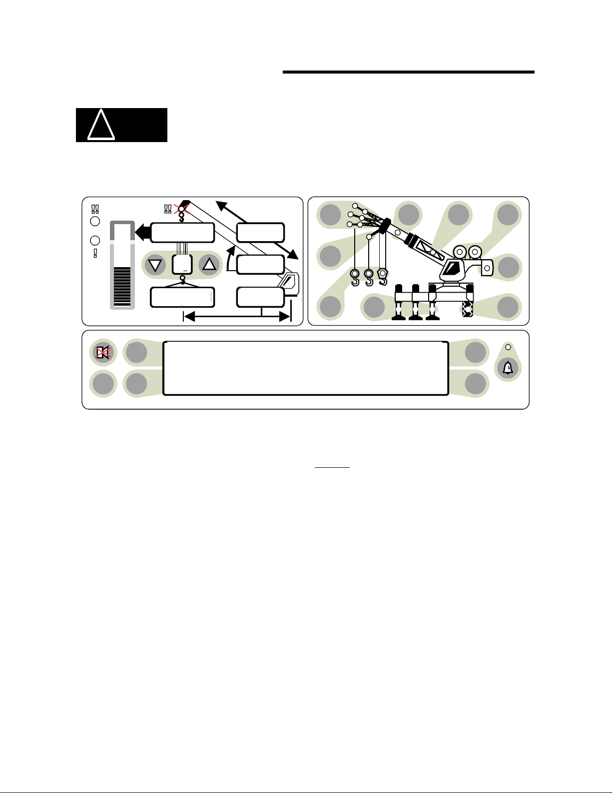
ORs Full 9.7Klb Ctwt
ERECTED 60' TELEJIB 17 AUXHD ON
PICK FROM MAIN BOOM FRONT WINCH
TEST
MAX
SET
360
o
6
23,500
i2,300
44.8
62.7
26.4
oC
D
B
A 03 Zero Sensor

GREER COMPANY
Crane Systems
GREER COMPANY 1918 East Glenwood Place, Santa Ana, CA 92705 TEL: (714) 259-9702 FAX: (714) 259-7626
MicroGuard® RCI 510/400 CALIBRATION MANUAL PN W450189A 09/09/02
18 of 65
COMMAND 03 ZERO - EXTENSION SENSOR
The extension reel, fitted with 130 ft. of shielded 2-wire cable, cannot be shortened to
accommodate varying boom lengths.
IMPORTANT: Ensure that the boom is in a horizontal position when performing this routine.
COMMAND 03 ZERO PRETENSION ROUTINE – EXTENSION SENSOR
1) Fully retract all boom sections.
2) Remove the clamp on the reel cable and allow it to slowly rewind onto the reel until there is
no pretension.
3) Continue to rewind the reel until the distance between the attachment point and the end of
the cable is approximately 12 ft. Due to the clutch on the reel shaft, there will now be no
pre-tension.
4) Pull the cable toward the anchor point, continuing until the end of the cable is 3 ft. Beyond
the anchor point.
5) Secure the cable to the anchor point with at least 4 wraps, ensuring that there is sufficient
cable at the boom head to connect to the anti two-block switch, which is terminated in a
3-pin plug.
6) Manually turn the large gear on the potentiometer fully counterclockwise. Then, advance the
gear clockwise three clicks.
7) Calibrate the zero of the sensor, as shown on the next page.

GREER COMPANY
Crane Systems
GREER COMPANY 1918 East Glenwood Place, Santa Ana, CA 92705 TEL: (714) 259-9702 FAX: (714) 259-7626
MicroGuard® RCI 510/400 CALIBRATION MANUAL PN W450189A 09/09/02
19 of 65
COMMAND 03 ZERO - EXTENSION SENSOR CONTINUED
COMMAND 03 ZERO ROUTINE – EXTENSION SENSOR
IMPORTANT: Ensure that the boom is in a horizontal position when performing this routine.
1) PRESS ATO 03 ZERO SENSOR.
2) PRESS CTO START THE COMMAND.
3) PRESS ATO ZERO NO. 2 XXXX (ACTUAL INPUT).
4) PRESS CTO START CALIBRATION OF THE 03 ZERO SENSOR.
5) PRESS CTO CALIBRATE OR PRESS D TO ABORT THE CALIBRATION OF ZERO NO. 2.
AFTER THE MESSAGE, “CALIBRATING” ENDS,
THE DISPLAY SHOULD READ: ZERO NO. 2 XXXX (ZEROED INPUT).
6) PRESS DTO EXIT THE ROUTINE OR PRESS ATO CHANGE THE SENSOR.
ORs Full 9.7Klb Ctwt
ERECTED 60' TELEJIB 17 AUXHD ON
PICK FROM MAIN BOOM FRONT WINCH
TEST
MAX
SET
360
o
6
23,500
i2,300
44.8
62.7
26.4
oC
D
B
A 03 Zero Sensor

GREER COMPANY
Crane Systems
GREER COMPANY 1918 East Glenwood Place, Santa Ana, CA 92705 TEL: (714) 259-9702 FAX: (714) 259-7626
MicroGuard® RCI 510/400 CALIBRATION MANUAL PN W450189A 09/09/02
20 of 65
COMMAND 03 ZERO - BOOM ANGLE SENSOR
Use great care when calibrating the boom angle sensor. All subsequent calculations are
dependent on the accuracy of this calibration.
Use an inclinometer or measuring device with an accuracy of +/- 0.25 when calibrating the
boom angle sensor. Use of a less accurate device may result in calibration errors.
IMPORTANT: Ensure that the boom is in a horizontal position
when performing this routine.
♦Using an inclinometer, set the boom in a horizontal position.
♦The boom angle sensor is mounted inside the d3l0022 housing.
Mount the extension sensor perpendicular to the boom.
♦Calibrate the zero of the boom angle sensor (page 21).
Table of contents
Popular Construction Equipment manuals by other brands


Hagie
Hagie UpFront 120ft BOOMS Operator's manual

Manitowoc
Manitowoc National Crane NBT40-1 Series Service manual

Carlton
Carlton SP8018 owner's manual

Northern Industrial
Northern Industrial 144207 instruction manual

IMER
IMER MOVER 190D Operating, maintenance, spare parts manual

Parkside
Parkside PFMR 1400 A1 Original operating instructions