IMER SMALL 50 Guide

08/2004
- Cod. 3224463 -
IMER INTERNATIONAL S.p.A.
53036 POGGIBONSI (SIENA) loc. SALCETO
(ITALY)
tel. 0577 97341 - fax 0577 983304
INTONACATRICE
GUNITEUSE
MORTAR MIXER
VERPUTZMASCHINE
ENFOSCADORA
( 1106040 )
Manuale uso manutenzione ricambi
Manuel utilisation entretien pièces de rechange
Operating, maintenance, spare parts manual
Handbuch für Bedienung, Wartung und Ersatzteile
Manual de uso, mantenimiento y recambios
EL
PDF compression, OCR, web-optimization with CVISION's PdfCompressor

2
IMER INTERNATIONAL S.p.A.
INTONACATRICI IMER
ENGLISH
FRANÇAIS
DEUTSCH
ESPAÑOL
14
11 10
12
13
5
8
7
1
1b
1a
2
2a
4a
4b
6
9
3
4
15
1) VIBROSETACCIO
1a) SENSORE VIBRO
1b) VIBRATORE
2) COPERCHIOTRAMOGGIA
2a) SENSORE COPERCHIO
3) LANCIA SPRUZZATRICE
4) SCHIACCIA SACCHI
4a) MANOVELLA
4b) RULLO
5) GRIGLIA TRAMOGGIA
6) TRAMOGGIA
7) QUADRO ELETTRICO
8) MOTORIDUTTORE
9) AGITATORE
10) ROTORE - VITE ECCENTRICA -
11) STATORE - VITE ECCENTRICA -
12) TUBO USCITA MATERIALE
13) ATTACCO A CAMME
14) SENSORE MACCHINA
15) ATTACCHI ARIA
Particolare attenzione deve essere fatta alle avvertenze contrassegnate con questo simbolo:
Il faut prêter une attention toute particulière aux notes précédées de ce symbole :
Special attention must be given to warnings with this symbol:
Lesen Sie die mit diesem Symbol bezeichneten Abschnitte mit besonderer Aufmerksamkeit:
Se tiene que prestar una atención especial a las indicaciones marcadas con el signo:
1) TAMIS VIBRANT
1a) CAPTEUR VIBRO
1b) VIBRATEUR
2) COUVERCLE TREMIE
2a) CAPTEUR COUVERCLE
3) LANCE DE VAPORISATION
4) ECRASE-SACS
4a) MANIVELLE
4b) ROULEAU
5) GRILLE TREMIE
6) TREMIE
7) TABLEAU ELECTRIQUE
8) MOTOREDUCTEUR
9) AGITATEUR
10) ROTOR - VIS EXCENTRIQUE -
11) STATOR - VIS EXCENTRIQUE -
12) TUBE SORTIE MATERIAU
13) FIXATION A CAMES
14) CAPTEUR MACHINE
15) RACCORDS AIR
1) RÜTTELSIEB
1a) SENSOR RÜTTLER
1b) RÜTTLER
2) TRICHTERDECKEL
2a) SENSOR DECKEL
3) SPRÜHPISTOLE
4) SACKPRESSE
4a) KURBEL
4b) WALZE
5) TRICHTERGITTER
6) TRICHTER
7) SCHALTTAFEL
8) GETRIEBEMOTOR
9) RÜHRWERK
10) ROTOR - EXZENTERSCHNECKE -
11) STATOR - EXZENTERSCHNECKE -
12) MATERIALAUSTRITTSROHR
13) NOCKENANSCHLUSS
14) SENSOR MASCHINE
15) DRUCKLUFTANSCHLÜSSE
1) VIBRATING SCREEN
1a) VIBRO SENSOR
1b) VIBRATOR
2) HOPPER COVER
2a) COVER SENSOR
3) SPRAY JET
4) BAG SPLITTER
4a) HANDLE
4b) ROLLER
5) HOPPER GRID
6) HOPPER
7) ELECTRICAL PANEL
8) GEARMOTOR
9) MIXER
10) ROTOR - CAM SCREW-
11) STATOR - CAM SCREW -
12) MATERIAL OUTFEED HOSE
13) CAM COUPLING
14) MACHINE SENSOR
15) AIR CONNECTIONS
1) VIBROTAMIZ
1a) SENSOR VIBROTAMIZ
1b) VIBRADOR
2) TAPA DE LA TOLVA
2a) SENSOR TAPA
3) PISTOLA DE PROYECCIÓN
4) PRENSA DE SACOS
4a) MANIVELA
4b) RODILLO
5) REJILLA DE LA TOLVA
6) TOLVA
7) CUADRO ELÉCTRICO
8) MOTORREDUCTOR
9) AGITADOR
10) ROTOR - TORNILLO EXCÉNTRICO -
11) ESTATOR - TORNILLO EXCÉNTRICO -
12) TUBO SALIDA MATERIAL
13) RACOR TIPO CAMLOCK
14) SENSOR MÁQUINA
15) CONEXIONES DE AIRE
PDF compression, OCR, web-optimization with CVISION's PdfCompressor

18
IMER INTERNATIONAL S.p.A.
accessories, as described in paragraph 4.2.
4.2 DESCRIPTION OF MAIN ACCESSORIES REQUIRED
FOR THE RANGE OF APPLICATIONS
SMALL 50 is undoubtedly the smallest and most versatile pump
available. There are manifold applications in which this pump
represents the ideal solution in terms of operation and speed. By
the simple addition or replacement of an accessory, SMALL 50
can be adapted to diverse requirements. For this reason, it is
important to be aware of the wide range of accessories available,
to enable full exploitation of the potential of this machine.
IMER INTERNATIONAL is available, through their dealers and
authorised service centres to evaluate your requirements and
find the ideal solution.
Commonly used optional accessories (see fig.1):
- IMER VIBRO - SCREEN code no. 1107510
- This accessory replaces the hopper grid and is
therefore equipped with a safety sensor.
It must be used when the material is to be mixed on site with
collection of aggregate from a loose storage deposit: in this
case some aggregate may have a larger particle size than
admissible values, which could obstruct the spray outlet or cause
premature wear of the stator
After removing the hopper grid (ref.5), position the screen on
the hopper (ref. 6) and make the electrical connection with the
machine’s electrical panel (fig.5,ref. 12), fitted with the vibrator
on/off control.
Operation: after positioning and connecting the machine, and
before pouring the material into the hopper, set the main switch
to ON to start up the vibrator. Pour in the required material and on
completion turn the switch to OFF, removing any residue trapped
in the screen.
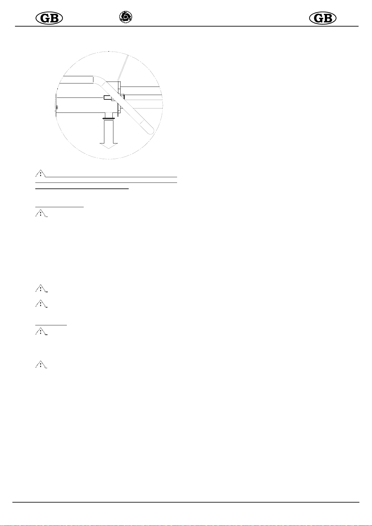
- HOPPER COVER (see fig.2)
IMER code no.1107513
- This accessory replaces the hopper grid and is
therefore equipped with a safety sensor.
It is used to close the hopper and isolate the contents from air
and possible impurities: finishing colour, finishing mortar etc. This
delays drying of the materials thus enabling prolonged storage
time in the hopper.
Position at the top of the hopper (ref. 5) with or without the
hopper grid (ref. 6),
- IMER BAG SPLITTER code no.1107511
It is used to speed up and optimise emptying of the bags containing
the wet material ready to use (e.g. the most common lime-based
finishing mortar).
It features simple connection to the machine. If necessary the
roller crushing pressure can be adjusted as required: loosen the
screws to reduce and tighten to increase.
Intuitive operation: lay out a bag of material lengthwise on the
hopper grid, move the protruding flap of the sack towards the
rollers (ref. 4b), use the right hand to slightly turn the rollers
clockwise by means of the handwheel (ref. 4a), so that the bag
is trapped between the rollers. Use a cutter to open the sack at
the other end, and turn the rollers until the bag is totally emptied.
The material is now in the hopper ready to be pumped.
Dear Customer,
compliments on your purchase: this IMER mortar mixer, the
result of long-standing experience in the field, features maximum
reliability and innovative technical solutions..
- WORKING IN SAFETY..
To ensure complete safety, read all the instructions in
this manual carefully.
This OPERATION AND MAINTENANCE manual must be kept by the Site
Manager and be always available for consultation.
The manual is considered part of the machine and must be stored
for future reference ( EN 12100-2 ) through to scrapping of the
machine itself. If the manual is lost or damaged, a replacement
copy can be ordered from the manufacturer.
The manual contains the EC declaration of conformity (98/37/EC)
important information on construction site procedures, installation,
operation, maintenance and requests for spare parts. Nevertheless,
the user must both have adequate experience and knowledge of the
machine prior to use: the user should be trained by a person totally
familiar with the operation and use of this machine.
To guarantee complete safety of the operator, safe operation
and long life of equipment, follow the instructions in this manual
carefully, and observe all safety standards currently in force for
the prevention of accidents at work (use of safety footwear
and suitable clothing, helmets, gloves, goggles etc.).
- Make sure that all signs are legible.
- Never make any modifications to the metal structure
or mortar mixer systems.
IMER INTERNATIONAL accepts no responsibility in the event of
failure to comply with laws governing the use of this type of
equipment, with particular reference to: improper use, incorrect
power supply, lack of maintenance, unauthorised modifications,
failure to comply, either wholly or partially, with the instructions
set out in this manual.
IMER INTERNATIONAL reserves the right to modify the
characteristics of the mortar mixer and/or contents of this manual,
without the obligation to update the previous machine and/or
manuals.
1. TECHNICAL DATA
Table 1 provides the technical specifications of the mortar mixer,
with reference to figure 1.
2. DESIGN STANDARDS
The mortar mixers have been designed and constructed
according to the standards specified in table 1.
3. NOISE EMISSION LEVEL
Table 1 shows the sound pressure levels of the mortar mixer
measured at the ear of the operator (L
pA
at 1 m - 98/37/CE) and
noise emission levels in the environment (power L
WA
) measured
according to EN ISO 3744 (2000/14/CE).
4. DESCRIPTION OF MORTAR MIXER OPERATION
- THE CAM SCREW mortar mixer is designed for use
in building sites, for pumping, injecting or spraying all
wet or pre-mixed materials, compatible with this type of
machinery: liquid cement, adhesives, finishing products,
levelling products, waterproofing, finishing colours,
grouting, traditional mortars or pre-mixed products,
plasters with a lime/cement base or gypsum, fire-proof
insulants etc.
4.1 DESCRIPTION OF MORTAR MIXER (see fig.1)
The mortar mixer comprises a wheeled frame (ref. N), which
supports a hopper (ref. 6) with grid (ref. 5), an electrical panel
(ref.7), a gearmotor (ref. 8), which, by means of a mixer (ref.
9) activates a cam screw pump (ref. 10/11) that conveys the
material via a rubber hose to the jet (ref. 3).
If the material is sprayed, air is also delivered to the jet by
means of a compressor (optional).
The mortar mixer can be controlled by means of: pneumatic
control, electrical via cable (radio control-optional).
The flow rate is controlled by means of the buttons (+) and (-)
on the control panel.
The flow rate is shown (0=min, 100=max) on the electrical
panel display. The mortar mixer can be combined with various
FIG.2
PDF compression, OCR, web-optimization with CVISION's PdfCompressor

19
IMER INTERNATIONAL S.p.A.
IMER MORTAR MIXERS
5. OPERATION SAFETY
- Before using the mortar mixer, ensure that it is
fitted with all safety devices.
- Never insert parts of the body and/or tools in the
hopper .
All current standards governing accident prevention and safety
devices must be observed in the workplace.
Take care when handling bags of material, to avoid sprays which
may come into contact with the eyes or other parts of the body.
Wear safety goggles and gloves. Avoid the dispersion of dust
which may be inhaled. Always wear a mouth and nose protection
mask during use.
- Never use the machine in areas subject to the risk of
explosion/fires or in underground installations.
The mortar mixer is not equipped with a lighting system and
therefore the workplace must be fitted with adequate lighting.
The power lines must be laid to prevent any possible damage.
Never place the mortar mixer on electric power cables.
Ensure that the electrical connection is protected against the risk
of water penetration in connectors. Use exclusively connectors
and couplings equipped with water spray protection.
- Never use inadequate or provisional electric lines; if in doubt
consult specialist personnel for assistance.
- Repairs to the electrical circuit must be performed exclusively
by specialised personnel. Disconnect the machine from the power
supply before performing maintenance or repairs.
-
Avoid contact of electric wires with movable and/or moving
parts of the machine to avoid injury from contact with live metal
parts
.
6. ELECTRICAL SAFETY
The
SMALL 50 mortar mixer is constructed according to standard EN
60204-1, with protection against water sprays and protection against
overload and power failure.
The mortar mixer
must be connected to the earthing circuit.
- Caution ! Keep hands away from the rollers when
turning to avoid the risk of fingers becoming trapped.
- IMER COMPRESSORS code no.3224528 IMER code
no.1107516
The air delivered by the compressor to the spray jet via a rubber
hose is used to spray the pumped material. Compressors with
different air flow rates can be applied on the machine: from 180
l/min to 600 l/min of air output. The selection of the type of
compressor to be used is based on the type of material handled
and the type of application. In general, the greater the air flow
rate, the finer the material spray delivered.
The 180 l/min compressor is suitable for most products which,
after spraying on walls require manual distribution (thick
applications: plaster, grouting, finishing mortar etc...). A
compressor with greater output is required for all products, which,
once sprayed uniformly onto the walls, do not need special
spreading operations, or which are only smoothed (thin layer
applications: levelling products, colours, some finishing mortars,
waterproofing agents etc.).
IMER code no.1107516, is an autonomous compressor. It is
connected to the site panel and the pneumatic circuit of the
machine.
- Caution ! For installation, connections, operation
and maintenance, refer to the compressor instruction
manual.
- This compressor is connected directly to the site
mains electrical panel.
This enables machine start-up when the air line is open and
shutdown when it is closed. The compressor is equipped with
an auto-shutdown system, overload cut-out, and main switch,
which lights up when the unit is powered.
Maintenance: Check the air filters weekly, clean or replace when
necessary, above all if working in excessively dusty
environments (see compressor “operation and maintenance”
manual).
It is positioned in the vicinity of the mortar mixer and connected
directly to the spray jet hose.
In this case the machine is turned on and off from the jet position,
using the remote control supplied with the mortar mixer, or the
optional radio control.
- RADIO CONTROL code no.1107518
Enables remote control of machine start-up/shutdown with
electrical cable connections.
The receiver is installed in the electrical panel.
The receiver is extremely practical; it can be held in the hand,
pocket or fixed to the spray jet, outlet or other element by means
of magnets. To turn on the machine, press ON, and to shut down
press OFF.
- Caution ! Protect the unit from water jets; it must
never get wet.
- PRESSURE GAUGE code no. 1107512
This is a control instrument used to read pressure levels in the
material hose lines.
For example: in the case of using traditional mortar at the maximum
flow rate of 100 on the panel display, and if pressure exceeds
15 bar (maximum pump pressure). To prevent tripping of the
machine protection devices, simply reduce the material flow rate
by pressing the pushbutton (-) on the electrical panel, until the
value falls below 15 bar.
PDF compression, OCR, web-optimization with CVISION's PdfCompressor

20
IMER INTERNATIONAL S.p.A.
IMER MORTAR MIXERS
7. MECHANICAL SAFETY
The hazardous points on the IMER mortar mixer are protected
by means of suitable safety devices, which must remain fitted
at all times and kept in perfect condition, such as the electric
motor cooling fan guard, the grid on the hopper, the vibro-
screen and the hopper cover to prevent contact with the mixer.
All elements are connected to a safety sensor: when disen-
gaged, all moving parts of the machine are shut down.
8. TRANSPORT (see fig.3/4)
- Caution! Before moving the mortar mixer, always
detach the power plug.
Before moving the mortar mixer the air hose and material delivery
line must be removed.
Only a minimal amount of the material should be in the hopper
when handling.
Move the machine by means of the specific handles.
- Caution! Before lifting the mortar mixer, always
disassemble the compressor for separate transport.
- Caution! Before lifting the machine, always check
that all machine components are correctly secured and
fitted in place.
To lift the machine, use the three specific attachment points.
- Caution! Lift with care to avoid hazardous
oscillations
- Caution! Never use points other than as specified
in figure 3 to lift the machine.
Use lifting equipment suited to the overall weight of the machine
indicated in table 1.
9. INSTALLATION
Position the mortar mixer in a suitably ventilated environment
where it does not constitute an obstruction either during use or
cleaning at the end of the work shift and where a minimum
quantity of pipelines is required.
Place the machine according to the application in a clear area if
ready-to-use bags are fed into the machine: below the mixer
outlet in the case of mixes being mixed on site. The machine
must always be placed on a flat surface or slightly inclined
towards the material outlet.
Route machine pipelines as required by the product application,
avoid excessive bends or kinks on the hoses. If pipelines are
routed upwards, secure the lines to scaffolding or other support
points.
Apply or connect the accessories required fro the specific
application, with reference to paragraph 4.2
Always connect the remote control supplied in the case of use
without compressed air or when using compressors with
capacity of over 400 l/min
10. CONNECTIONS
10.1 ELECTRICAL CONNECTION (see fig.5)
- Ensure that the power supply voltage, mains
frequency and electrical connection (socket, fuses, cable)
correspond to specifications in table 1.
The electrical power line must be fitted with protection against
current overload (e.g. by means of fuses or a thermal magnetic
cut-out) and against indirect contact (e.g. with a differential
circuit breaker). The electric cable wire size must take into
account the operating currents and length of the line to avoid
excessive voltage drops.
Avoid use of extension leads wound on drums. The power
cable must be suitable for frequent movements and with an
abrasion resistant sheath (e.g. type H07RN-F).
Before connecting the mortar mixer to the electrical mains,
ensure that all safety devices are fitted and are in perfect
condition, and check in particular that the hopper grid is secured
in place, that the extension in good condition and that the plugs
and sockets are not wet.
Connect the mortar mixer socket on the electrical panel to the
mains.
FIG.3
FIG.4
FIG.5
10.2 AIR CONNECTION
FOR SPRAYING ONLY
In the case of compressors with outputs up to 400 l/min connect
the air delivery directly to the jet as in the case of control of the
machine by means of the incorporated pneumatic control (see
par.4.2).
The machine can be controlled by means of the electric pendant
control supplied. This solution is also possible for compressors
with output below 400 l/min.
PDF compression, OCR, web-optimization with CVISION's PdfCompressor

21
IMER INTERNATIONAL S.p.A.
IMER MORTAR MIXERS
11. START-UP (see fig.6)
After positioning the machine, prepare a bucket with a
quantity of approx. 10l. of grout. Pour the grout into the
machine hopper, or, in the case of using colorant products,
directly in the machine pipelines before connection. In the
latter case, pour approx. 10l. of coloured product into the
hopper. Check the material hoses to ensure perfect
condition, that couplings are intact and the relative seals are
fitted, then connect them to the delivery manifold and spray
jet. Check that the cam levers ( A ) of the couplings have
been tightened correctly and that the seal (B) is fitted as
shown in fig. 6a.
Close the spray jet valve (ref. 15a), turn the main switch
(ref. 3) to 1(ON), switch on the optional compressor if used,
and turn the selector (ref. 7) clockwise to the start position.
The pushbuttons (+) flow rate (ref. 6) and (-) flow rate (ref.
5), control the flow rate as shown on the display (ref. 8) at
30. Open the spray jet air valve (or pneumatic control)(ref.
15d) or start the machine by means of the electric remote
control: the pump starts to rotate slowly. Depending on the
machine configuration, wait until the grout in the hopper
reaches the level of the mixer, or until the coloured product is
delivered from the jet. At this point shut down the machine by
means of the pneumatic or electric control, fill the hopper and
start work as required. Adjust the quantity of material
delivered from the jet as required, by means of pushbuttons
(+) and (-). When the electric remote control is connected,
the selector should be set to the start position. The machine
is controlled exclusively by means of the electric remote
control.
The machine is fitted with protection against power failure: if
this occurs, the main switch must be reset to restart the machine
(turn from 0 to 1).
To stop the machine in the event of an emergency, press the
red emergency button (ref. 2) To isolate the machine, all moving
parts are shut down and then turn the main switch to 0 and
remove the electric power plug from the socket (ref.1
1).
1
3
79
2
10 12
11
654
13 14
8
15
a
15
15
b
15c
15
d
( A )
FIG.6b
( B )
FIG.6a
The machine must never be started up or remain in operation if
there is no material in the hopper, to avoid premature wear of the
stator and screw.
-
Never direct the jet towards yourself or others
PDF compression, OCR, web-optimization with CVISION's PdfCompressor

22
IMER INTERNATIONAL S.p.A.
IMER MORTAR MIXERS
OVERLOAD AND ELECTRICAL PROTECTIONS
-
The electric motors are protected against overload by
thermal magnetic cut-outs, the activation of which is indicated by
total shutdown of the machine. In this case, after the motors have
cooled, the specific personnel should reset the main switch to
resume operation.
For the pump motor there is an additional safety protection: a
thermal sensor shuts down the machine in the event of a motor tem-
perature overload.
-The inverter device housed inside the electrical panel is
equipped with protections for the event of a power failure
or if power exceeds the set admissible limits, voltage
fluctuations caused by other site utilities, overload of
the electric motor due to improper use or overheating of
the inverter.
Activation of these safety devices is indicated by
illumination of a red light (ref. 9), in which case,
authorised personnel must remedy the cause and
resetthe safety device via the main switch, turning it from
0 to 1.
- The main switch on the electrical panel (ref. 3) is only
enabled when: power is connected to the protection grid
or the vibroscreen is fitted on the machine.
12. OPERATION (see fig.1)
-
The hopper safety grid must always be fitted.
Never place materials other than premixed wet materials
in the hopper.
-
Removal of the hopper grid or vibro-screen causes
shutdown of the machine moving parts. If this occurs,
the grid or vibro-screen must be refitted and the main
switch must be reset to restart the machine.
- Wear envisaged personal protection devices before
starting work
Interruptions exceeding 30min should be avoided, and in any
event these pauses should be reduced to the minimum possible
when using rapid-drying materials
Prolonged shutdown can cause clogging in the material delivery
lines: in this case no material is delivered from the jet and the
pressure gauge indicates a higher pressure than the normal
working value.
In this case, turn the selector anticlockwise (opposite position
to normal work setting), the pump motor rotates in the opposite
direction and the pipelines are depressurised. As soon as the
pipeline becomes soft and flexible (the pressure gauge reads
0 bar), stop the machine.
Locate the point of clogging in the hose and remove by tapping
the hose with a rubber mallet and totally empty by hand.
- If necessary, disconnect the jet or open the pipeline
couplings, checking previously if any residual pressure is
present.
The material pressure gauge must indicate 0 bar and the
pipelines, excluding the clogged sections, must be flexible.
The personnel assigned for this task must be specially trained
in these procedures.
In the event of any doubt as to the presence of residual pressure,
never open the couplings.
Reconnect the pipelines and spray jet, set the main switch to the
correct position and restart the machine.
- Do not move the machine with the hopper full.
A reduction in material flow to the jet may indicate a worn pump.
To replace the pump, proceed as follows: with the machine
empty and clean, remove the hopper grid, tilt the machine with
manifold upwards, remove the wedges, with the aid of a mallet,
and at the same time remove the delivery manifold, screw and
stator (fig.N).
To insert the screw in the stator, use the lubricant spray available
from IMER. Never use mineral oil or grease for screw assembly
as this may damage the stator. Avoid all types of benzene.
Refit the pump taking care to insert the mixer in the envisaged
seats.
In the case of a power failure during operation,
clean the machine
and pipelines immediately. Also disassemble the pump, remove
the screw from the stator and clean. On completion reassemble
all components.
Refit the pump taking care to insert the mixer in the envisaged
seats.
13. MACHINE SHUTDOWN AND CLEANING
At the end of work, stop the machine after completely emptying
the hopper by means of the relative selector and set the main
switch to 0.
- Open the jet valve, detach the jet and clean thoroughly, cleaning
the nozzle with the special tool supplied.
- Before disconnecting the jet or pipelines, ensure that
there is no residual pressure.
-Disconnect the material pipelines from the delivery manifold.
-Remove the hopper grid or vibro-screen and clean thoroughly.
-Remove the plug at the bottom of the hopper and use water to
wash the machine thoroughly, starting from the bag splitter if
installed
- Refit the plug in the hopper and fill with water.
-Restart the machine for a few seconds until clean water is
delivered from the manifold: this confirms complete cleaning of
the pump.
- While the pipelines are still full, insert two cleaning sponges
and refit the pipeline in the manifold (fig.8)
- Start the machine again so that the water in the hopper is
pumped through the pipelines to remove all residue.
When the two sponges are delivered from the hose, washing
is complete.
- At this point, on completion of machine cleaning, turn off the
main switch, and disconnect the power plug.
FIG.7
FIG.8
PDF compression, OCR, web-optimization with CVISION's PdfCompressor

23
IMER INTERNATIONAL S.p.A.
IMER MORTAR MIXERS
If there is any risk of freezing, open the hopper plug, disconnect
the pipelines and drain all water from the circuit (fig.9).
- Before opening the drain plug or the grid, ensure
that the main switch is turned to 0 and the plug is
disconnected from the power supply.
14. MAINTENANCE
- Maintenance must be performed by adequately
trained personnel, after switching off the machine,
disconnecting it from the power supply and emptying
the hopper.
Check weekly that the compressor air filter is clean. If
deteriorated, replace.
Check weekly that the electric motors are free of dust and dirt
and if necessary clean using compressed air.
Check weekly that the plug and socket contacts are clean, dry
and rust free.
Every six months arrange for an inspection of the machine by
an authorised IMER service centre.
-
Spent oil is a special waste. Therefore it must be
disposed of according to current legislation.
-
Always keep notices and symbols on the machine
legible.
15. REPAIRS
- Never start up the mortar mixer during repairs.
Repairs to the electrical installation must be performed
exclusively by specialised personnel.
Use exclusively original IMER spare parts; modifications
to parts are strictly prohibited.
- If any guards are removed for repairs, ensure they
are refitted correctly at the end of work.
FIG.9
PDF compression, OCR, web-optimization with CVISION's PdfCompressor

24
IMER INTERNATIONAL S.p.A.
IMER MORTAR MIXERS
FAULT CAUSE CORRECTIVE ACTION
Machine does not start,
compressor does not start
and the blue light is OFF
Electric current
-
No current delivered to connector of site panel (fuses)?
- No power delivered to machine
(defective connector connection? loose cable?)
- Main swiitch not turned on
- Check points listed alongside
The machine does not
start but the compressor
starts no signal on display
Electric current
(blu lamp on= main switch in correct position?)
- Operating selector not in start position
- Hopper grid missing
- Plug not inserted correctly in socket
- Remote control connected?
- Spray jet nozzle dirty or clogged
- Supply voltage too high (over 250 volt)
- Check points listed alongside
- Start unit up from remote control
- Clean nozzle with special cleaner
The machine starts but
stops immediately
ERR00
ERR04
Material
-Material binding properties low
(mortar pump seized?)
- Material too dry
--Empty the hopper, ensure that the screw is not
blocked. when the machine is clean, restart with liquid
cement taking care to mix the solution with at least
400/500 kg of binder per cubic metre:
- Bring the density of the material equal to that of a
plastering mortar by adding water
- Work with lower flow rates
Material flow to the gun
stops.
A red light illuminates on
the electrical panel
ERR00
ERR04
Clogging
-Material hose clogged
-Spray jet clogged
- Low level of binder in mix
- Sand not suitable for mix
- Remove obstruction
- Connection to compressor detached
- Bodies in mix with too large section
- Use sand with constantly optimal particle size curve.
The machine stops during
operation The following texts appear on display
-ERR00 : Material pressure or friction on screw too high
- ERR01 :Inverter temperature too high
- ERR02 : Motor temperature too high
- ERR03 :Inverter module current too high
- ERR04 :System overload
- ERR05 :supply voltage too low
- Reduce flow rate before restarting
- Low level of binder in mix, add cement or lime
- Sand not perfectly suitable for pumping; correct
- Pipeline length excessive; reduce
- Wait for the motor to cool sufficiently before
restarting
- Check the power line.
- Wait for the motor to cool sufficiently before
restarting
- Probable external short circuit
- as per ERR00
- Pump seized -
- Check that the power voltage is between 210 and
230 Volt with the machine running and that the cables
are correctly sized, and that there is no other
equipment (cranes, hoists, saws, cement mixers etc.)
connected to the same power line
PDF compression, OCR, web-optimization with CVISION's PdfCompressor

40
IMER INTERNATIONAL S.p.A.
INTONACATRICI IMER
.TAV. 1 - STRUTTURA MACCHINA - STRUCTURE MACHINE - MACHINE STRUCTURE - MASCHINENAUFBAU - ESTRUCTURA DE LA MAQUINA
Rif.
Cod.
I F
GB
D E
Note
1
3224226
TELAIO
CHÂSSIS
FRAME
RAHMEN
BASTIDOR
2
3224235
QUADRO ELETTRICO
TABLEAU ÉLECTRIQUE
ELECTRICAL PANEL
SCHALTTAFEL
CUADRO ELÉCTRICO
3
3224228
RETE
RÉSEAU
MESH
NETZ
RED
4
3224452
MOTORIDUTTORE
MOTORÉDUCTEUR
MOTOR-REDUCTION
GEAR
GETRIEBEMOTOR
MOTOREREDUCTOR
5
3224225
TRAMOGGIA
TRÉMIE
HOPPER
TRICHTER
TOLVA
6
3224234
MANIGLIONE
POIGNEE
HANDLE
GRIFF
ASAMANGUERA
7
3224227
TUBO USCITA
MATERIALE
TUYAU SORTIE
MATERIAU
MATERIAL OUTLET HOSE
MATERIALAUSLAUFLEIT-
UNG
SALIDA MATERIAL
8
3223721
ATTACCO A CAMME
M-F
RACCORD M-F CAM CONNECTION M-F
NOCKENANSCHLUSS
(STECKER-BUCHSE)
RACOR TIPO CAMLOCK
M-H
DN25
M. 1"-G F.
9
3224457
STATORE
STATOR STATOR
STANDER
ESTATOR
D.8-1.5
ECO MONOFASE
10
3223719
CONI MORSE CÔNES ÉTAUX
CLAMPING CONES
KEGEL
CONOS MORDAZAS
25x7 L=150mm
11
3224459
ROTORE
ROTOR ROTOR
LÄUFER
ROTOR
12
3223720
TIRANTE
TIRANT
TIE-ROD
STREBE
TIRANTE
13
2222060
VITE
VIS
SCREW
SCHRÄUBE
TORNILLO
M8x16 Z
14
2224140
ROSETTA
RONDELLE
WASHER
UNTERLEGSCHEIBE
ARANDELLA
15
3224233
ASTA TRASMISSIONE
16
3209809
RUOTA
ROUE
WHEEL
RAD
RUEDA
17
2224719
ROSETTA
RONDELLE
WASHER
UNTERLEGSCHEIBE
ARANDELLA
25X50X4
18
2226700
COPIGLIA
GOUPILLE
SPLIT PIN
SPLINT
PASADOR
D.3.5 Z
19
3224232
BOCCOLA
TRASMISSIONE MOTORE DOUILLE TRANSMISSION
MOTEUR
MOTOR TRANSMISSION
BUSHING
BUCHSE
MOTORANTRIEB
CASQUILLO
TRANSMISIÓN MOTOR
20
3224231
FLANGIA GUARNIZIONE BRIDE JOINT
FLANGE SEAL
DICHTUNGSFLANSCH
BRIDA JUNTA
21
3224230
GUARNIZIONE
JOINT
GASKET
DICHTUNG
JUNTA
22
3224229
FLANGIA MOTORE
PALA
BRIDE MOTEUR AUBE
FLANGE MOTOR
PADDLE
FLANSCH
SCHAUFELMOTOR
BRIDA MOTOR PALA
23
3224237
ANELLO PARAOLIO
PARE-HUILE
OIL SEAL
OLDICHTUNG
GUARDAGOTOS
24
3224506
VITE
VIS
SCREW
SCHRAUBE
TORNILLO
5911
M8x20
25
3207209
GOLFARE FEMMINA
CHEVILLE À OEILLET
FEMELLE
FEMALE EYEBOLT
RINGBUCHSE
ARGOLLA HEMBRA
M10
26
3223707
TAPPO
BOUCHION D'EXTRÉMITÉ
PLUG
VERSCHLUßSTOPFEN
TAPÒN TERMINAL
27
2223570
DADO
ECROU
NUT
MUTTER
TUERCA
M8
28
2223806
DADO
ECROU
NUT
MUTTER
TUERCA
5588
D.16 Z
29
3224115
VOLANTINO
ROUE À MAIN
HAND WHEEL
HANDRAD
VOLANTE
732-40
M8x20
30
3224505
INGRASSATORE
GRAISSEUR
GREASE NIPPLE
SCHMIERNIPPEL
ENGRASADOR
TIPO B16 A 60°
1/4"
31
3224243
BOCCOLA NYLON
CALAMITA
DOUILLE NYLON AIMANT MAGNET NYLON
BUSHING
NYLONBUCHSE MIT
MAGNET
CASQUILLO NYLON IMÁN
32
3223385
MAGNETE
AIMANTS
MAGNET
MAGNETE
MAGNETOS
D.13x10
SC35NI
33
3224239
SENSORE
CAPTEUR
SENSOR SENSOR SENSOR
PDF compression, OCR, web-optimization with CVISION's PdfCompressor

41
IMER INTERNATIONAL S.p.A.
INTONACATRICI IMER
SCHEMA ELETTRICO - SHEMA ELECTRIQUE - WIRING DIAGRAM - SCHALTAPLAN - ESQUEMA ELECTRICO
ALIMENTATION
COMPRESSEUR
COMPRESSOR
POWER SUPPLY
STROMVERSORGUNG
KOMPRESSOR
ALIMENTACIÓN
COMPRESOR
SECTEUR220V
220VMAINS
NETZ 220 V
RED 220 V
CONTROLE CONTROL KONTROLLE
URGENCE
EMERGENCY
STÖRUNG
EMERGENCIA
PRESSION
PRESSURE
DRUCK
PRESIÓN
START/STOP INVERSION
INVERSION START/STOP
START/STOPP
INICIO/PARADA INVERSIÓN
AUGMENTE
INCREASE
BEWEGUNGSUMKEHR
AUMENTAR
DIMINUE
DECREASE
STEIGERN
DISMINUIR
MICRO SECURITE
SAFETY MICRO
SICHERHEITSMIKROSCHALTER
MICROINT. SEGURIDAD
LIGNE
LINE
LINIE
LÍNEA
COMMANDEADISTANCE
REMOTE CONTROL
REMOTE-KONTROLLE
MANDO REMOTO
INV. FAULT
INV. FAULT
INV. FAULT
FALLO INVERS.
U1INVERTERIMER U1INVERSEUR IMER IMERU1INVERTER U1INVERTERIMER U1 INVERSORIMER
MOTORE POMPA
MOTEUR POMPE
PUMP MOTOR
PUMPENMOTOR
MOTOR BOMBA
PDF compression, OCR, web-optimization with CVISION's PdfCompressor
Other manuals for SMALL 50
2
This manual suits for next models
1
Table of contents
Other IMER Construction Equipment manuals