gc MG 500 User manual

MG434/500 Prototype Commissioning Manual PN W453101Rev- Nov-02-1998
MG 500
Rated Capacity Indicator System
Prototype Calibration and Testing for:
Machine Model
Serial Number
Tester
Date

Page 2 of 28
M434/500 Prototype Commissioning Manual PN W453101Rev- Nov-02-1998
Introduction
This document describes the process by which MicroGuard systems using the “Supercal” concept are set
up for use on a new crane model. If correctly followed, this procedure will ensure accurate and fast
calibrations of subsequent calibrations on the same model machine.
Procedures within this document are intentionally written as a step-by-step guide to enable the calibrating
engineer to correctly determine the characteristics of the machine. The calibrating engineer is further
assumed to be conversant with calibration methods operated through the MG434 display panel as
described within the MG434 / 500 Calibration procedure manual, and with the 5-Charts software used to
create a capacity chip for the system.
Throughout the following procedures, certain checks are applied to data that should have already been
entered as part of the capacity chip data entry (5-Charts). It is highly recommended that each of these
checks are methodically applied in order to save time and problems with future installations.
It is intended that the calibrator use this document as a method to record measured dimensions and test
results, in order that subsequent modifications to the capacity chip file can be made against this record.
This further will provide an on-file record which may serve future upgrades and changes to MicroGuard
designs.
Notice
This document and resulting data about the crane are confidential.
Copies of this document may not be distributed to third parties in any
form without the prior written consent of the Greer Company and the
crane manufacturer.
Tools Required
PC with 5-Charts Software
EPROM programmer with link to above PC.
A copy of machine geometric data supplied by the crane data sheet (and within the 5-Charts capacity
chip file for this machine).
Spare 27C020/27C002 EPROMS
Digital Volt/Ohmmeter
Inclinometer – accurate to 0.1degrees
Measuring tape
Hand tools

Page 3 of 28
M434/500 Prototype Commissioning Manual PN W453101Rev- Nov-02-1998
Preliminary checks
Before commencing calibration, it is important that certain checks of the machine geometry be made.
Geometric values have been previously entered into the capacity chip from the crane application data
sheet filled out by the crane manufacturers engineering department.
Measure the following dimensions and check against the values specified within the capacity chip file
entered into the 5-charts program.
Note the dimensions measured and verify that they match data within the capacity chip file.
If any discrepancies are found, they must be immediately repaired and a new capacity chip created in
order to continue. Establish the source of the error and ensure that if possible, it cannot occur again.
The following pages provide a list of measurement checks to be made. Measured values should be
entered in the spaces provided.
The checks in the following pages include:
Boom Hoist Geometry
Boom Hoist Cylinder
Winch #0 Geometry
Winch #1 Geometry
If the measurements do not verify with the data contained within the capacity chip, do not continue with the
calibration before ensuring that they are corrected and a new chip is programmed.
Page 4 of 28
M434/500 Prototype Commissioning Manual PN W453101Rev- Nov-02-1998
Boom Hoist Geometry
Measure each dimension shown using a tape. It is at best, a difficult exercise to measure these
dimensions, but still a necessary check. It is recommended that two people carry out this task and that
care is taken to ensure that clear references are used to measure from.
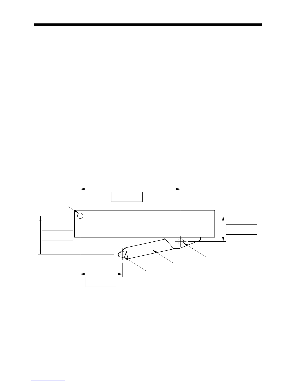
Dimension “L” is the distance parallel to the boom center line between the center of the Boom pivot and
the center of the upper Boom Hoist cylinder pivot.
Dimension “J” is the distance at 90 degrees to the boom center line between the center of the Boom
pivot and the center of the upper Boom Hoist cylinder pivot.
J is negative when the Boom pivot is above the upper Boom Hoist cylinder pivot and positive when it is
below.
Dimension “G” is the horizontal distance between the center of the Boom Pivot and the center of the
lower Boom Hoist cylinder pivot.
Dimension “H” is the vertical distance between the center of the Boom pivot and the center of the lower
Boom Hoist pivot.
It is recommended that the boom is level when measuring dimensions “L” and “J”.
The carrier is assumed to be level for the purposes of measuring dimensions “G” and “H”.
Enter the measured values into each of the gray boxes provided below.
*If the boom foot pin is above the Boom Hoist cylinder Upper Pivot (as shown), dimension “J” is
negative. Clearly indicate “+” or “-“. The above illustration shows dimension “J” as negative.
H
J
GBoom Hoist Cylinder
Boom
Boom Pivot
Low er Pivot
Upper Pivot
L
*

Page 5 of 28
M434/500 Prototype Commissioning Manual PN W453101Rev- Nov-02-1998
Front Winch Geometry
Measure each dimension shown using a tape. It is at best, a difficult exercise to measure these
dimensions, but still a necessary check. It is recommended that two people carry out this task and that
care is taken to ensure that clear references are used to measure from.
The boom must be fully retracted and is recommended to be level during these measurements.
The machine carrier is assumed to be level for the purposes of measuring dimensions “G” and “H”.
Dimension “L0” is the distance parallel to the boom center line between the center of the Boom pivot
and the point at which the hoist rope makes contact with the top sheave at the head of the main boom.
Dimension “J0” is the distance at 90 degrees to the boom center line between the center of the Boom
pivot and the point at which the hoist rope makes contact with the top sheave at the head of the main
boom.
Dimension “G0” is the horizontal distance between the center of the Boom Pivot and the center of
rotation of the winch.
Dimension “H0” is the vertical distance between the center of the Boom pivot and the center of rotation
of the winch.
H0 is negative when the center of the Boom pivot is above the center of rotation of the winch and positive
when it is below.
Dimension “r0” is the radius of the winch drum and should include two layers of rope.
Enter the measured values into each of the gray boxes provided below.
*If the center of the boom pivot is above the center of rotation of the winch, dimension “H0” is negative.
Clearly indicate “+” or “-“. The above illustration shows dimension “H0” as positive.
H0* J0
G0
Boom Hoist C
y
linder
Boom
Boom Pivot
L0
r0 Top Sheave
Winch 0 (Front)

Page 6 of 28
M434/500 Prototype Commissioning Manual PN W453101Rev- Nov-02-1998
Rear Winch Geometry
Measure each dimension shown using a tape. It is at best, a difficult exercise to measure these
dimensions, but still a necessary check. It is recommended that two people carry out this task and that
care is taken to ensure that clear references are used to measure from.
The boom must be fully retracted and is recommended to be level during these measurements.
The machine carrier is assumed to be level for the purposes of measuring dimensions “G” and “H”.
Dimension “L1” is the distance parallel to the boom center line between the center of the Boom pivot
and the point at which the hoist rope makes contact with the top sheave at the head of the main boom.
Dimension “J1” is the distance at 90 degrees to the boom center line between the center of the Boom
pivot and the point at which the hoist rope makes contact with the top sheave at the head of the main
boom.
Dimension “G1” is the horizontal distance between the center of the Boom Pivot and the center of
rotation of the winch.
Dimension “H1” is the vertical distance between the center of the Boom pivot and the center of rotation
of the winch.
H1 is negative when the center of the Boom pivot is above the center of rotation of the winch and positive
when it is below.
Dimension “r1” is the radius of the winch drum and should include two layers of rope.
Enter the measured values into each of the gray boxes provided below.
*If the center of the boom pivot is above the center of rotation of the winch, dimension “H1” is negative.
Clearly indicate “+” or “-“. The above illustration shows dimension “H1” as positive.
H1* J1
G1
Boom Hoist C
y
linder
Boom
Boom Pivot
L1
r1 Top Sheave
Winch 1 (Rear)
Page 7 of 28
M434/500 Prototype Commissioning Manual PN W453101Rev- Nov-02-1998
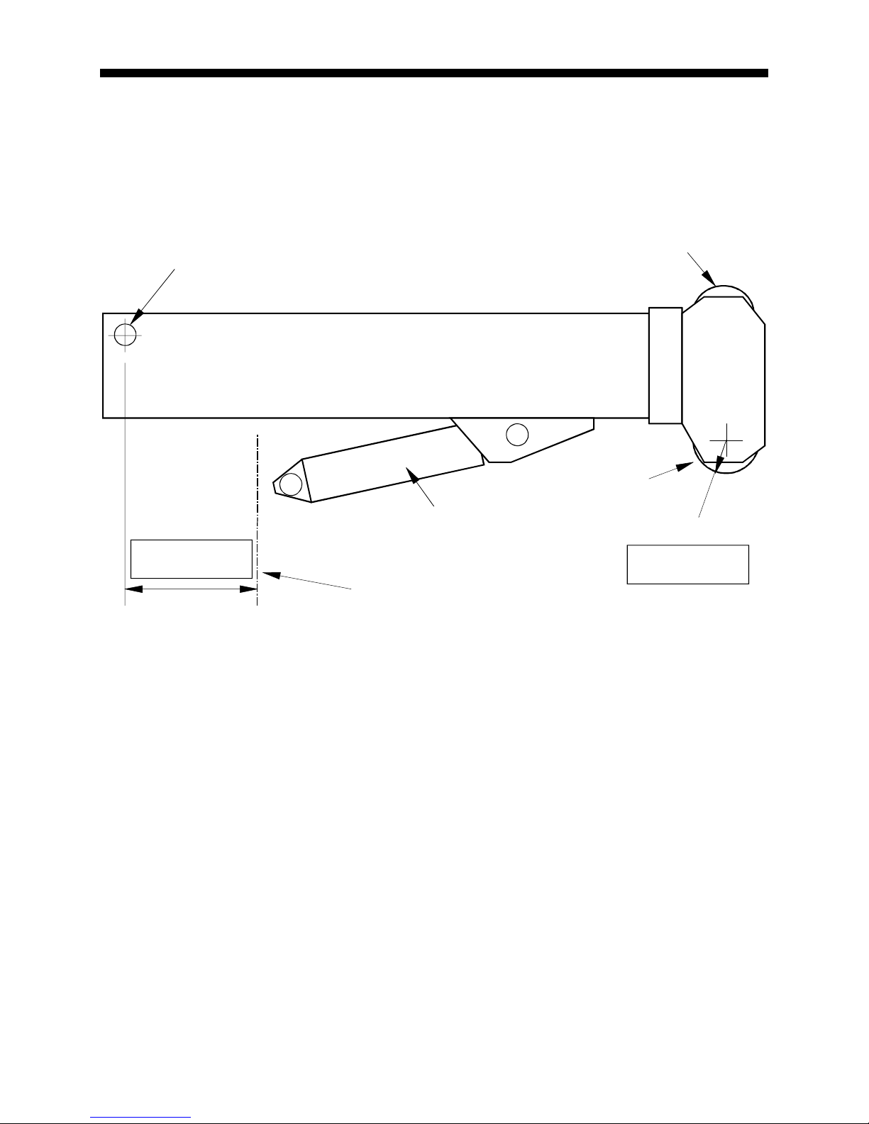
Miscellaneous Data
The following checks are for Main Boom Head Sheave Radius and Swing Offset.
Swing Offset is negative when the boom pivot is behind the center of rotation.
Enter the measured values into the gray boxes provided.
Installation checks
Before continuing, make sure any necessary changes to geometrical data found in the previous
pages have been made to the capacity chip file and a new capacity chip has been created and
installed.
Check wiring and EPROM installations.
If swing switches are fitted, check that these operate correctly, by using the digital input monitor routine
through the MicroGuard display.
Set the reeling Drum Clutch
Boom Hoist Cylinder
Boom
Boom Pivot
Swin
g
Offset
Hd Shv radius
Top Sheave
Head Sheave
Center of Rotation

Page 8 of 28
M434/500 Prototype Commissioning Manual PN W453101Rev- Nov-02-1998
Reset Crane Data
Reset the systems crane data using the ‘Reset Crane Personality Data’ routine in the calibration
‘Crane Data’ menu selection. This process uses some of the geometric data entered in the capacity
chip to prepare the system for calibration.
See the calibration manual for instructions on how to use the routine.
Zero Angle sensor
Mechanically zero the Boom Angle Sensor. Instructions for setting the potentiometer are contained within
the Extension Reel installation manual.
Double check that the boom has been set level prior to setting.
Set the angle sensor pot voltage to 1/10th of the drive voltage at the extension reel (0.5V nominal)
Zero Extension Sensor
Mechanically zero the Boom Extension Sensor. Instructions for setting the potentiometer are contained
within the Extension Reel installation manual.
Double check that the boom is fully retracted prior to setting.
Set the reeling Drum zero by measuring the drive voltage and adjusting the pot until the extension voltage
is equal to 1/20th of the drive voltage (0.25V nominal)
Span Angle Sensor
It is essential that the angle sensor is spanned as accurately as possible (preferably to within 0.1
degrees).
Boom up to at least 60 degrees and measure the boom angle with an inclinometer. Be careful to check
that a correct reading is obtained from the inclinometer.
Calibrate the angle span.
Before continuing, check the angle at an intermediate point such as 35 degrees and ensure that the
inclinometer and angle reading match within 0.2 degrees.
Span Extension Sensor
Fully extend the boom and calibrate the span of the extension sensor. It may be necessary to check the
actual extension by measuring with a tape. For this the boom may need to be flat to obtain a
measurement (If it is possible).
For extension sensors measuring intermediate lengths, the extension should be known before spanning
the sensor. It is always a good idea to check by taping with the boom flat if possible.
NOTES:

Page 9 of 28
M434/500 Prototype Commissioning Manual PN W453101Rev- Nov-02-1998
Set Zero and Direction of Swing Pot.
Set the machine to the over front swing area and zero the swing pot. Swing the machine in a clockwise
direction (to the right) and set the direction indicator to ‘+’.
Check the swing angle shown increments as you swing the crane to the right, at 360 degrees the angle
indicator will roll over to zero degrees and you should be back over the front of the machine again.
Calibrate Main Boom(s)
It is necessary to calibrate radius, moment and deflection for each telescoping mode of the main boom.
Almost all machines have two telescoping modes of operation for the boom. This would include:
Main boom – manual retracted
Main boom – manual extended
Main boom – Power pinned section retracted
Main boom – Power pinned section extended
Main boom mode A
Main boom mode B
Up to four main booms may be calibrated (normally two). The correct configuration must be selected
before carrying out each boom calibration.
Follow all steps – Radius/Moment, Boom deflection correction and Boom Head angle for each Main
Boom Telescoping Mode.
Make sure the correct Boom configuration is selected before continuing.
Note: - Head angle calibration is also required for each boom mode that is capable of erecting a fly.

Page 10 of 28
M434/500 Prototype Commissioning Manual PN W453101Rev- Nov-02-1998
Calibrate Radius/Moment
Up to seven points may be calibrated for each boom-telescoping mode. These points must include fully
retracted and fully extended. Intermediate points should be chosen to be where individual sections of the
boom start to telescope and/or other sections stop telescoping as the boom is extended.
For booms that exhibit an appreciable amount of flexibility or droop, it may be necessary to include an
extra point to improve accuracy, especially if there is a long distance between obvious points of
calibration. This is usually pertinent for long proportional booms, which might only require a fully retracted
and fully extended calibration.
Some booms exhibit a sudden droop near to fully telescoped, this is often due to the design and fitting of
wear pads inside the boom, which allow sections to hang on each other when near to their fully
telescoped limit. Though this has little affect on main boom radius accuracy, flys/jib radius may be
affected by this characteristic. It is essential here to add an extra calibration point at about 90% of the
boom extension.
Calibrate Radius/Moment by following the procedure in the calibration manual. Take care to accurately
measure the radius at each calibration point. Using a single part of line will aid this.
When entering the Tare load in the calibration routine, it is usually a good idea to add a little to the hook
weight. Adding 100 pounds (or 50 Kilos) will help guarantee a slightly positive load reading in all
operating configurations.
NOTES:

Page 11 of 28
M434/500 Prototype Commissioning Manual PN W453101Rev- Nov-02-1998
Boom ________
Boom
Extension 0
Boom
Extension 1
Boom
Extension 2
Boom
Extension 3
Boom
Extension 4
Boom
Extension 5
Boom
Extnsion 6
EXTN
LEN_S
WG
WT
Boom ________
Boom
Extension 0
Boom
Extension 1
Boom
Extension 2
Boom
Extension 3
Boom
Extension 4
Boom
Extension 5
Boom
Extnsion 6
EXTN
LEN_S
WG
WT
Boom ________
Boom
Extension 0
Boom
Extension 1
Boom
Extension 2
Boom
Extension 3
Boom
Extension 4
Boom
Extension 5
Boom
Extnsion 6
EXTN
LEN_S
WG
WT
Boom ________
Boom
Extension 0
Boom
Extension 1
Boom
Extension 2
Boom
Extension 3
Boom
Extension 4
Boom
Extension 5
Boom
Extnsion 6
EXTN
LEN_S
WG
WT

Page 12 of 28
M434/500 Prototype Commissioning Manual PN W453101Rev- Nov-02-1998
Calibrate Boom deflection
Fully extend the boom at a high angle of greater than 60 degrees and lift the same load used to calibrate
the pressure. Calibrate the boom deflection by following the instructions in the calibration manual.
It is a good idea to add 0.1ft or 0.1m to the radius when entering the radius in the calibration for boom
deflection. This will help ensure a slightly positive radius in most operating conditions.
Record the deflection value (F factor) displayed in the calibration screen in the appropriate position below.
Boom ________ Deflection
Boom ________ Deflection
Boom ________ Deflection
Boom ________ Deflection
NOTES:

Page 13 of 28
M434/500 Prototype Commissioning Manual PN W453101Rev- Nov-02-1998
Calibrate Boom Head Offset
The boom head offset is required to aid the computer to correctly calculate the radius of flys/jibs.
During the process of checking and recording the boom head angle the boom will need to be fully
telescoped at zero degrees. Check that the machine can achieve this safely before continuing. If not the
boom will need to be elevated and readings taken at higher boom angles.
Some booms exhibit a sudden droop near to fully telescoped, this is often due to the design and fitting of
wear pads inside the boom, which allow sections to hang on each other when near to their fully
telescoped limit. Though this has little affect on main boom radius accuracy, flys/jib radius may be
affected by this characteristic. It is essential here to add an extra calibration point at about 90% of the
boom extension.
Fully retract the boom and attach an inclinometer to the boom head.
Set the boom level (0.0 degrees) and set the inclinometer to read 0.0 degrees (use zero reference button
if the inclinometer has one).
Telescope the boom about 50% of it’s max extension or for a boom mode with a sequence change, the
first point of sequence change.
Record the extension value, the boom angle display and the inclinometer reading.
Telescope to the next step (or full extension) and record the new readings.
When all readings have been taken, subtract the boom angle value from the boom head inclinometer
value to obtain the actual head offset and record this in the table.
Use the boom head calibration routine to enter the extension values and boom head angle. See the
calibration manual for details on using the boom head calibration routine.
Note: The boom head angle goes more negative as the boom extends. The boom head angle to be
entered will be negative for almost every known boom design.
Also note that no head angle calibration is required for boom s that do not allow a fly – jib erection.
Boom ________
Boom Extension Boom Angle Boom Head Angle Difference

Page 14 of 28
M434/500 Prototype Commissioning Manual PN W453101Rev- Nov-02-1998
Boom ________
Boom Extension Boom Angle Boom Head Angle Difference
Boom ________
Boom Extension Boom Angle Boom Head Angle Difference
NOTES:

Page 15 of 28
M434/500 Prototype Commissioning Manual PN W453101Rev- Nov-02-1998
Test Main Boom
Following each main boom calibration perform a series of tests that will sufficiently show the accuracy of
the calibration in all working areas of the main boom.
Test the unladen boom, two different loads at three different lengths and three different angles for each
length of main boom.
Boom ________
Displayed
Length
Displayed
Angle
Displayed
Radius
Measur’d
Radius
Radius
Error
Displayed
Load
Actual
Load
Load
Error
Notes

Page 16 of 28
M434/500 Prototype Commissioning Manual PN W453101Rev- Nov-02-1998
Boom ________
Displayed
Length
Displayed
Angle
Displayed
Radius
Measur’d
Radius
Radius
Error
Displayed
Load
Actual
Load
Load
Error
Notes

Page 17 of 28
M434/500 Prototype Commissioning Manual PN W453101Rev- Nov-02-1998
Boom ________
Displayed
Length
Displayed
Angle
Displayed
Radius
Measur’d
Radius
Radius
Error
Displayed
Load
Actual
Load
Load
Error
Notes

Page 18 of 28
M434/500 Prototype Commissioning Manual PN W453101Rev- Nov-02-1998
Test Auxiliary Head
The auxiliary head should be checked for radius accuracy as a minimum. Load testing is optional since
the attachment is only a short extension to the main boom. Check that the auxiliary head dimensions
specified in the capacity chip file either specify an effective vertical and horizontal offset or length and
angular offset only.
Test with the empty hook and measure the radius in at least three positions.
Displayed
Length
Displayed
Angle
Displayed
Radius
Measur’d
Radius
Radius
Error
Displayed
Load
Actual
Load
Load
Error
Notes
NOTES:

Page 19 of 28
M434/500 Prototype Commissioning Manual PN W453101Rev- Nov-02-1998
Test Attachments
There is little calibration required to set up fly’s and jibs. The most likely requirement is for a deflection
correction. The deflection correction may be applied to each attachment by calibrating with the bdc
command. Do not calibrate bdc unless unloaded tests are complete and satisfactory, and the main boom
radius accuracy is correct.
The angular offset of the fly is normally the dimension that requires change in the capacity chip during
testing. Since all fly’s fit to the boom head using the same physical attachments, the offset angle of all
fly’s with the same offset may be modified at the same time.
Test the longest fly at all of it’s offsets before making corrections to the capacity chip and continuing with
other attachment testing.
Data collected from the main boom calibrations may be added to the capacity chip at this time also.
Test sequence
Start testing with the longest attachment at the straightest offset angle.
It is a good idea to check the length and vertical offset dimensions of the attachment with a tape before
commencing tests. If necessary correct the values of these in the capacity chip.
The following tests should be done on each attachment:
Test Fly Offset Boom
Length
Boom
Angle
Load Comments
1* Straight Retracted 0 Hook Establish that fly length is correct
through radius accuracy (+/-0.2ft)
2* “ “ >60 “ Establish that fly offset angle is correct
through radius accuracy (+/-0.2ft)
3* “ Extended >60 “ Establish Fly moment accuracy (-0 to
+0.2lbs*1000)
4* “ Retracted >60 >50%
Capacity
Attachment deflection correction
Note the bdc “F” factor
5 “ “ Low to High
3-angles
“ Load Test
6 “ Mid-Range “ “ Load Test
7 “ Fully
Extended
“ “ Load Test
8* First
Offset
Retracted >60 Hook Establish that fly offset angle s correct
through radius accuracy (+/-0.2ft)
9 “ “ Low to High
3-angles
“ Load Test
10 “ Mid-Range “ “ Load Test
11 “ Fully
Extended
“ “ Load Test
12* Second
Offset
Retracted >60 Hook Establish that fly offset angle is correct
through radius accuracy (+/-0.2ft)
13 “ “ Low to High
3-angles
“ Load Test
14 “ Mid-Range “ “ Load Test
15 “ Fully
Extended
“ “ Load Test
• Indicates that an adjustment to the capacity chip data may be required following these checks.

Page 20 of 28
M434/500 Prototype Commissioning Manual PN W453101Rev- Nov-02-1998
Attachment Tests
Attachment &
Offset
Main Boom
Test #
Test
#
Displayed
Length
Displayed
Angle
Displayed
Radius
Measur’d
Radius
Radius
Error
Displayed
Load
Actual
Load
Load Error
Table of contents


