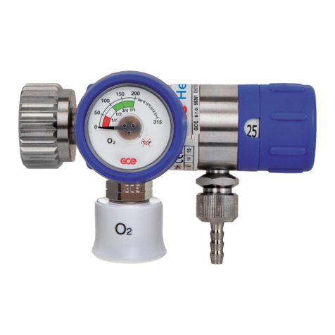
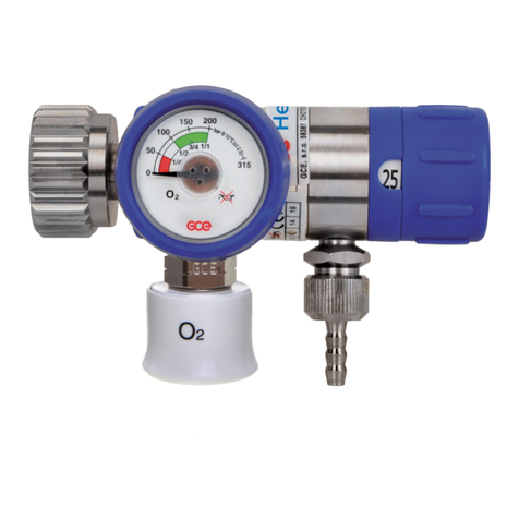
GCE MediVital E User manual

INSTRUCTION FOR USE
NÁVOD K POUŽITÍ
BEDIENUNGSANLEITUNG
ISTRUZIONI PER L'USO
GEBRUIKSAANWIJZING
GCE VALVES
PRESSURE REGULATORS INTEGRATED
WITH CYLINDER VALVES EN
MediVital®E
REDUKČNÍ VENTILY S INTEGROVANÝM
UZAVÍRACÍM VENTILEM PLYNOVÝCH LAHVÍ CS
DRUCKREGLER MIT FLASCHENVENTILEN DE
REGOLATORI DI PRESSIONE
CON VALVOLA DELLA BOMBOLA INTEGRATA IT
NL
DRUKREGELAARS MET GEÏNTEGREERDE
CILINDERKLEPPEN

2/132
EN
1. FOREWORD
The product complies with the essential requirements of 93/42/EEC Medical Device Directive
and Transportable Pressure Equipment Directive 2010/35 EU. The combination valve is
designed according to EN ISO 10524-3 and EN ISO 10297 standards.
TERM MEANING
MEDIVITAL®E Combination valve MediVital®E is equipped with an electronic pressure
indicator E-GAUGE
EGAUGE Electronic indicator
DISPLAY Electronical indication device
2.INTENDED USE
MediVital®E Combination Valves are designed to be fitted to gas cylinders used for medical
gases. These combination valves together with a gas cylinder form gas packages used either
as gas supply point for medical devices (anaesthetic devices, ventilating devices, incubators
etc.) or for direct gas supply to a patient’s breathing mask or cannula.
GCE Combination Valves are intended to be used with the following medical gases:
• Oxygen
• Nitrous oxide
• Air for breathing
• Helium
• Carbon dioxide
• Mixtures of the gases listed above.
MediVital®E combination valve is not intended for use with flammable anaesthetics and
substances.
2.1. PATIENT PROFILE
Medivital®E supplies medical gas by means of the control flow head in flow range from 0 to 15
(25) l/min.
Saturation of the medical gas must be prescribed by the doctor or an anaesthetic nurse who
has got the medical education, assessed the heath status of the patient and supplies him with
required amount of the medical gas.
Health status - the assesment and decision about the use timing and dosage amount
requirements of the patient is up to the doctor or medical personnel.
Medical personnel - nurse, rescuer, paramedic or carer who has obtained medical education.
2.2. USER PROFILE
Use in the hospital or ambulance:
• Education: personnel with medical education
Home care use:
Therapy is prescribed by a doctor or personnel who has got a medical education in the field of
breathing support:
• Knowledge: training of personnel with medical education who has got an ability to read, train
and apply knowledge from the instruction for use.
Training must be performed according to regulations valid in each country.
Important:
Patient must be trained by the doctor or person who has got an education in the life saving.
ENGLISH
INSTRUCTION FOR USE: MEDIVITAL®E

3/132
EN
3.OPERATIONAL, TRANSPORT AND STORAGE SAFETY
REQUIREMENTS
KEEP THE PRODUCT AND ITS ASSOCIATED EQUIPMENT AWAY FROM:
• Heat sources (fire, cigarettes,...)
• Flammable materials
• Oil or grease (take a great care in the use of hand creams)
• Water
• Dust
The product and its associated equipment must be prevented from tipping over, turning over
or falling.
Always maintain oxygen cleanliness standards.
Only use the product and its associated equipment in well ventilated area.
Before the first use the product shall be kept in its original package. If removed from service
(for transport, storage) GCE recommends using the original package (including inner packing
materials). National laws, rules and regulations for medical gases, accident prevention and
environmental protection must be observed.
OPERATING CONDITIONS STORAGE AND TRANSPORT CONDITIONS
MIN MAX MIN MAX
-20 °C* +65 -40 °C +70 °C
10 % 100 % 10 % 100 %
600 mbar 1200 mbar 600 mbar 1200 mbar
*for inner tightness of the shut-o valve, during transport and storage of the combination valve
mounted on a cylinder, the valid lower temperature limit is -40°C.
If the valve is used in the reach of a patient, the ambient temperature must not exceed 40°C.
When used in home care, the acclimatization time after a change of conditions from storage
(or transport) to operational must be at least 1 hour.
In case of the combination valve storage temperature drops below -20°C do not use the
combination valve until its temperature reaches at least -20°C.
In case the ambient valve temperature drops below -10°C or rises above +40°C, the battery is
being self-discharged, and therefore the lifetime is shortened.
For the combination valves designed to be used with mixture of gases O2+N2O, the lowest
operating temperature is +5°C. In normal use of the combination valve, frosting can appear on
the combination valve surface, which is caused by the gas inside the combination valve when
high pressure in the combination valve cooling when high pressure gas is being reduced to
low pressure (Joule-Thomson eect).
O2+N2O mixtures are temperature sensitive. N2O begins to separate out from the mixture if
the temperature falls below about -6°C. A homogenous mixture is again obtained when the
temperature has raised above 10°C and the cylinder was agitated. Before use, to ensure it is
properly mixed, cylinders should be stored horizontally for 24 hours at a temperature above
10°C. If this is not practicable, before use the cylinders must be maintained at a temperature
above 10°C for at least 2 hours and then completely inverted three times or placed in warm
water at body temperature for 5 minutes and then completely inverted three times.

4/132
EN 5.PRODUCT DESCRIPTION
A combination valve combines the function of a shut-o valve of a high pressure gas cylinder
and a pressure regulator for use with medical gases. Gas from the cylinder is first controlled
by the main shut-o valve then passed through the pressure regulator and finally delivered to
the patient through the flow outlet or the pressure outlet. The outlet pressure is fixed by the
manufacturer and each combination valve is provided with a low-pressure relief valve to protect
against failure of the pressure regulator.
There are three basic alternatives:
• combination valve with a quick-coupler outlet, the outlet pressure is constant, and the flow is
not controlled by the combination valve,
• combination valve with an outlet via calibrated nozzles, the outlet flow is controlled by the
combination valve and can be changed by the control head,
• the combination valve with both alternatives.
SHUT OFF VALVE STATUS INDICATOR:
4.PERSONNEL INSTRUCTIONS
The Medical Devices Directive 93/42/EEC states that the product provider must ensure that all
personnel using the product are provided with the instructions & performance data.
Do not use the product without properly familiarization of the product and its safe operation
as defined in this Instruction for use. Ensure user is aware of particular information and
knowledge required for the gas in use.
fully OPEN
green
fully CLOSED
red
partly OPEN
red / green

5/132
EN
Marking detail
Inlet connection
type
Total weight
allowance of the
package
Filling port type
End of lifetime
Reference
number
Inlet pressure
Serial number
Compliance with
93/42 EEC
Compliance with
2010/35 EU
A INLET STEM
The combination valve is fitted to a gas cylinder by a threaded inlet stem. The inlet stem can
be taper threaded or parallel threaded with dierent sizes depending on the cylinder size and
material.
B FILLING PORT
A filling port is provided for filling the gas cylinder at a filling station, it has no function for
patient use. It includes a non-return valve (NRV). The NRV means that special filling adaptors
are required to vent gas from the cylinder during the filling process (venting and/or vacuuming
cylinders).
C ELECTRONIC INDICATOR EGAUGE
The E-GAUGE is intended for indicating the amount of gas inside the gas cylinder and the
remaining time of gas supply at the current flow. The indicator is active, i.e. the amount of gas
in cylinder is indicated regardless to shut-o valve position. More information can be found in
Chapter 5.1 - ELECTRONIC INDICATOR E-GAUGE.
D SHUTOFF VALVE
The combination valve is provided with a shut-o valve to isolate the gas in the cylinder from
the rest of combination valve functions. It must be opened when filling the cylinder and patient
therapy. Part of the hand wheel is an indicator showing the open/close status of the shut-o
valve.
The shut-o valve´s open/close status indicator is for guidance only. The shut-o valve may
not be fully o when OFF status is showing. Fully closed status has to be checked by ensuring
the shut-o valve is turned fully clockwise until a firm resistance to the rotation is reached and
gas supply to the outlets has stopped.
The shut-o valve must not be used in the "partly ON" status because even though gas is
supplied to the outlets, the flow can be limited due to an insuciently opened shut-o valve.
E RESIDUAL PRESSURE VALVE
The combination valve is equipped with a residual pressure valve with a function to retain a
minimum positive pressure in the gas cylinder to avoid contamination of the cylinder content
by atmospheric air. During cylinder gas ventilation through the filling port the residual pressure
valve is bypassed.
F, G FLOW CONTROL HEAD “F” AND FLOW OUTLET “G” OPTION
The combination valve can be delivered with a flow control head “F”.This function is used to
supply adjustable gas flow rates (l/min) at atmospheric pressure directly to a patient through the
flow outlet “G”, for instance through a cannula or a facemask. The flow outlet “G“ is equipped
with a hose fitting (hose nipple) or a threaded type (for accessories to be connected using a
threaded connection).

6/132
EN
Movement of the flow outlet ‘G’ is normal due to the method of fixing in the main body. It does
not indicate a faulty flow outlet.
H PRESSURE OUTLET OR QUICK COUPLER OPTION
The combination valve may be fitted with a pressure outlet. The pressure outlet is supplied with
gas direct from the low-pressure part of the combination valve and it is fitted with a gas specific
medical quick coupling connector also called a “quick coupler”. The user can connect another
piece of equipment to this outlet with a gas specific male probe (see appendix No. 2). The quick
coupler self seals when the male probe is disconnected. This outlet is for supplying gas at a
controlled pressure to power medical devices, for instance a medical ventilator.
I PRESSURE RELIEVE VALVE OF THE LOW PRESSURE PART
The pressure relieve valve secures the low pressure part of the combination valve and
connected medical devices against over-pressure. If the gas pressure is decreased enough
after the pressure relieve valve activation, it will closes itself.
J EXCESS FLOW DEVICE OR DIP TUBE OPTION
Excess flow device ensures the safe ventilation of gas from the gas cylinder in case the
combination valve is broken above the inlet stem (e.g. cylinder fall). A dip tube does not have
such a function. The excess flow device and dip tube are to avoid contamination from the
cylinder entering the combination valve .
PRESSURE RELIEF DEVICE OF THE HIGH PRESSURE PART BURSTING DISC OPTIONAL
The high pressure relief device is intended to protect the cylinder and high pressure part of
the combination valve against damage caused by increased cylinder pressure. If the pressure
relief device has been activated, it will not reseal and the combination valve must be taken out
of service for repair (see Chapter 9).
Note: The colour of the product (especially the guard, flow control head and shut-o valve)
does not have to match the gas colour coding.
5.1. ELECTRONIC INDICATOR EGAUGE
5.1.1. DEVICE DESCRIPTION
5.1.1.1. General warnings and important safety information
The actual parameter of the gas pressure inside the cylinder is shown even if the valve is not
used or the quick coupler is used as an outlet.
Indication of the remaining time of gas supply is only active when the outlet from the flow
head is used.
At simultaneous use of flow head outlet and pressure outlet (quick coupler) the indicated
parameters of the remaining time of gas supply are not accurate. The manufacturer does not
recommend using both outlets simultaneously during operational mode by the manufacturer.
(see chapter 6.2.2.2.)
No parts of the E-GAUGE can be replaced / repaired by the user. In case of a defect, the
product must be sent back to the manufacturer.
The battery is only replaceable by trained service personnel. An attempt to exchange the
battery without an authorized service technician may lead to dangerous situations such as
excessive heat or fire.
Contraindication: No known contraindication exist. The E-GAUGE is only used to monitor the
gas pressure inside the cylinder and the remaining time of gas supply (only if flow head outlet
is used).

7/132
EN
5.1.1.2. General description
The E-GAUGE is used to show information about the pressure inside the gas cylinder and about
the remaining time of the gas supply - until the complete exhaustion of gas cylinder - at the
actually set flow (flow head outlet use only).
A ELECTRONICS
The electronics of the E-GAUGE is located in the
plastic guard. The LCD display is used to indicate
of the operational information.
B SENSOR OF THE FLOW CONTROL HEAD
POSITION
Inside the control unit there is an integrated
sensor of the flow control head position. It is
intended to detect the actual set flow to calculate
the time of the gas supply.
C – PRESSURE SENSOR
The pressure sensor installed in the valve port
provides a signal about the actual cylinder
pressure.
5.1.1.3. Storage and operational conditions
Storage and operational conditions are in compliance with the conditions for the complete
MediVital®E combination valve mentioned in the chapter 3.
5.1.1.4. Display description
Indications during operation of the flow control head.
A
B
A.
Remaining time until the cylinder pressure drops to 15
bar at an actual flow. The indicated parameter is regularly
updated. The remaining time is automatically compensated
by the variation of ambient temperature.
B.
Bar chart equal to the pressure inside the gas cylinder.
Indications when null flow is set or when the quick coupler is used
A
C.
Actual pressure in the gas cylinder.
A
B
C

8/132
EN
2D code
A.
The 2D code is intended for connecting the E-GAUGE
with a mobile application more easily.. Using Bluetooth
communication. The 2D code keeps information about
MAC address of E-GAUGE for filling stations or maintenance
purposes.
B:
Indication of "cylinder volume" parameter related to the
E-GAUGE setup. If the symbol ??L is displayed, it is
necessary to perform parameterization using the mobile
application. See par. 6.1.3
Conditions applying to the 2D code appearance: Measured
pressure < 2,5 bar (respectively 7 bar in the case of a new
valve)
Exit from the 2D code mode: As soon as the pressure
grows, the E-GAUGE switches to the standard display
(pressure measuring, remaining time calculating)
Empty display
If the ambient temperature drops below -35°C, the display
operation is terminated automatically. This function
protects against any incorrect indication of characters due
to the low temperature. The display is switched on again
when the temperature rises above -30°C. This function is
not related to the condition of the battery.
Residual pressure indication
A
Signalization of an incorrect RPV function.
A.
Symbol „R“ appears with a 30 min delay after the pressure
in cylinder drops below 2 bar.
Symbol „R“ disappears if actual pressure in the cylinder is
above 10 bar.
Security code
If the parameters "cylinder volume" and "pressure unit" are
modified using the mobile application, the new values can
be saved by inserting the 4-digit security code generated
by the E-GAUGE display into the input field in the mobile
application (see. 6.1.3).

9/132
EN
Deep sleep mode – low consumption of electrical energy
If the Medivital®E has not been in use for an extended
period (10 - 20 hours typically) and actual pressure in
cylinder is more than 15 bar at the same time.
If the Medivital®E has not been in use for an extended
period (10 - 20 hours typically) and actual pressure in
cylinder is less than 15 bar at the same time.
If zero pressure is indicated, the pre-set volume of the
cylinder is also displayed.
If the symbol ??L is visible (instead of a numeric value).
The parameter cylinder volume is not set and it is necessary
to configure it using the mobile application, see chapter
6.1.3.
This functionality is intended primarily for filling stations.
Activate the E-GAUGE by turning the flow head knob into any position for normal operation.
The indicated gas pressure in the cylinder depends on the ambient temperature. The function
of the E-GAUGE can be influenced by this feature, especially when there is a significant
variation in the ambient temperature.
The remaining time shown on the display is 5-10% shorter (in relation to the temperature,
cylinder size) than the real time in which the actual cylinder content would be emptied at a
constant flow. This fact provides the patient with a sucient security reserve time.

10/132
EN
5.1.2. VISUAL AND ACOUSTIC WARNINGS
Warning alarms are divided into two groups:
5.1.2.1. Operational alarms - related to the general use of the device. These are marked with a
warning triangle in the top part of the display.
Low pressure - first warning
• In case the cylinder pressure drops under 50 bar.
• The display background becomes black.
• The warning symbol is indicated
• The acoustic signal starts simultaneously with the flashing
red LED diodes located on the left of the display.
Low pressure - second warning
• In case the cylinder pressure drops under 15 bar.
• Information about the remaining time is exchanged by the
actual cylinder gas pressure value.
• The acoustic warning signal starts simultaneously with
the flashing the red LED diodes located on the left of the
display.
If the "Low pressure" alarm is shown, the remaining gas in the cylinder can be consumed
very quickly. Pay close attention to the cylinder, prepare a reserve gas supply, and possibly
discontinue the cylinder from service immediately.
Indication of the simultaneous use of a quick coupler and hose connection
• When the E-GAUGE detects significantly higher
consumption (about 4 l/min higher) than corresponding to
the flow outlet consumption only.
• Only the pressure parameter is displayed
• The warning symbol of QC (quick coupler) is indicated
• If the QC outlet flow is too low, this status may not be
detected.
• After the cylinder had been re-filled, the use of QC
quick coupling may be temporarily indicated during the
subsequent cooling down process.

11/132
EN
Tempering of the device
• The warning is indicated if the E-GAUGE indicates a
rapid change in temperature caused by eg. moving the
device between two rooms with a high dierence in
temperatures.
• Only the pressure parameter is indicated.
• The warning T symbol is indicated (temperature).
5.1.2.2. Error alarms - related to the evaluation of the error status of the device. These are
marked with a big warning triangle in the left part of the display (except the "Low battery
voltage" warning)
Low battery charge
• A warning is indicated when there is a low battery charge
(2,7V and less).
• The battery symbol is permanently indicated
• The battery symbol is static, it does not have an active bar
chart indicator and always includes one bar.
• The use of the device may continue but at the earliest
cylinder filling, the battery must be changed.
• The symbol may be indicated even when the battery
charge is OK, but the cylinder was moved to a room with
low ambient temperature. The symbol disappears when
the cylinder warms up again.
Error of the pressure measure
• A warning is indicated when there is a defect of pressure
sensor.
• The symbol ??? is indicated instead of the pressure or
remaining time.
• The PS (pressure sensor) is indicate.
• The bar chart is not indicated.
• Discontinue the cylinder from service immediately and
send it back to the owner of the filling station. Service
must be performed by a GCE certified service centre.
If MediVital®E is not used for long periods, check the display of the E-GAUGE every 3 months.
If the symbol is shown on the display, the valve can still be used, but the valve must
be replaced at the latest within 3 months of detecting this situation. If this is not done, the
operation of the E-GAUGE may be unexpectedly terminated.

12/132
EN
Error of the flow measure
• A warning is indicated when there is a defect of the low
head sensor, its disconnecting or if the flow control head
is outside the defined position (e.g. in between two flows).
• Only the pressure value is indicated.
• The warning symbol FS (flow sensor) is indicated.
• Discontinue the cylinder from service immediately and
send it back to the owner of the filling station. Service
must be performed by a GCE certified service centre.
No flow
• A warning is indicated if the selected position of the
control flow head is > 1 l/min but simultaneously no
decrease in the cylinder gas pressure is reported (e.g.
closed shut-o valve or throttled outlet hose)
• The evaluation time depends on the set flow and the
cylinder volume, typically 2-10 minutes.
• Only the pressure parameter is indicated.
• The warning symbol FE (flow error) is indicated.
• Check if the shut-o valve is open or if the hose is not
throttled. Perform necessary actions. If the indication
does not disappear within few minutes, discontinue the
cylinder from service.
• Evaluation of FE alert is blocked for flows under 1 l/min.
• The FE symbol can be hidden by switching of the flow
control head to dierent position.
An FE alert can be displayed incorrectly if the flow head control is set to low flow (1-2 l/min
typically) and the ambient temperature increase rapidly in the same time.
Device outside operational temperature
• A warning is indicated in case the valve is moved to a
room with temperature outside the allowed range of
operational temperature, see chapter 3.
• Only the pressure parameter is indicated.
• The warning symbol TC (thermal conditions) is indicated.
• If you want the Medivital®E to be operational, it must be
moved to a room which complies with the requirements
for allowed range of operation temperature (see chpt. 3).
5.1.3. BLUETOOTH
E-GAUGE is equipped with a Bluetooth module for wireless data communication in the licence-
free zone of 2,4 to 2,5 GHz. Bluetooth communication is mainly used for primary calibration of
the pressure sensor and the flow head sensor and for setting up of the configuration of the gas
cylinder size and type of the control flow head during assembly of the valve to the gas cylinder.
Operational frequency: 2,4 GHz ISM zone (zone for radio transmitting in industrial, academic
and medical field)
Eective radiation power: max. 3 dBm.

13/132
EN
Maximal distance for safety connection between the device with an installed mobile
application GCE eGauge and the E-GAUGE is 10 meters in an open space. In closed spaces
this distance shortens.
6.USE OF PRODUCT
6.1. OPERATIONS PERFORMED BY THE PROVIDER, DISTRIBUTOR
FILLING STATION
6.1.1. GUARD
A valve guard should be provided where possible. If the used guard complies with EN ISO 11117
standard the package of combination valve with guard and gas cylinder must meet the drop
test requirements according to EN ISO 10524-3.
The total weight of the package as marked on the combination valve must not be exceeded if
the GCE guard is used, the guard does not comply with EN ISO 11117 or no guard is used.
Note: Total weight of the package includes the weight of the combination valve, the weight of
the cylinder filled with gas to max. limit and all permanently fixed parts.
The guard must allow easy access to all controlling elements of the combination valve, must
not inhibit the connection of medical devices to the combination valve outlet (e.g. for the filling
adaptor), must not influence any functions of the combination valve (e.g. pressure relieve valve)
and inhibit the legibility of labels and markings.
If the used combination valve is equipped with an E-GAUGE, it is forbidden to use it without
a guard.
Be careful not to damage the external parts of the valve, e.g. the E-GAUGE.
6.1.2. FITTING THE COMBINATION VALVE TO A GAS CYLINDER
Observe oxygen cleanliness standards during installation.
• Check the combination valve and gas cylinder for visible damage (especially the inlet stem
thread of the combination valve and the thread of the gas cylinder).
• Check the combination valve and gas cylinder for contamination. If needed, apply the cleaning
procedure according to chapter 8. To clean the gas cylinder, refer to the cylinder manufacturer
cleaning procedure.
• Check if the total lifetime of the combination valve and the gas cylinder has not been exceeded.
• Ensure that the product inlet stem is compatible with the gas cylinder.
• Check the presence & the integrity of seals / sealing materials (PTFE tape, O-ring) on the inlet
stem.
• Check that the gas cylinder pressure rating is higher than inlet pressure of the combination
valve .
• For the version with a GCE guard take o the filling port protective cover.
• Ensure that the fitting equipment does not interfere with/or damage the guard and other parts
of the combination valve or cylinder.
• Check the device display for an indication of a specific value of "cylinder volume" parameter
in the lower right corner (see par. 5.1.1.4 – Deep sleep mode or par. 5.1.1.4 – 2D code) which is
factory pre-set. Install the valve to the corresponding cylinder with the indicated volume.
If the symbol ??L is visible on the display, set the volume of the cylinder using the mobile
application, see par. 6.1.3
• Assembly combination valve on gas cylinder To tighten the combination valve in the cylinder
use only the square surfaces of the combination valve body. The across flat size of square
surface is 26 mm. When fitting of the combination valve to the cylinder follow the torque
figures specified in EN ISO 13341.
• Return the filling port protective cover on the combination valve.

14/132
EN
The product is only designed for use with the gas specified on its marking. Never try to fit to
a gas cylinder specified for a dierent gas type.
If you suspect that the inner parts of the combination valve have been contaminated, it must
be discontinued from service immediately.
Do not exceed the maximum torque allowed for the cylinder. Excessive torque may damage
the combination valve thread preventing its reuse. Certain types of cylinders may require a
torque lower than specified in EN ISO 13341. Check the max. allowed torque value with your
cylinder supplier.
Multiple reassembly can damage the inlet stem thread.
Be careful not to damage the external components of the valve, such as the E-GAUGE.
6.1.3. SETTING UP THE EGAUGE
Is necessary to set the following parameters correctly for the E-GAUGE to function correctly:
• Volume of cylinder to which the E-GAUGE valve is installed [in litres]
• Physical units in which the pressure shall be displayed [bar/MPa/psi]
These parameters can be factory pre-set or they can be set or modified by the customer as
needed using the GCE eGauge mobile application.
6.1.3.1. Installation of GCE eGauge mobile application
Request an application installation file and an access PIN to set up your E-GAUGE. Use the
installation file to install the mobile application on your device with the operating system
Android 5 or higher.
Note: To start the installation, enable the function "install applications from unknown sources"
in the Android operating system.
6.1.3.2. Description of the mobile application
Starting the mobile application
Start the GCE eGauge mobile application by clicking the
appropriate icon. This icon will appear on the mobile device
desktop after successful installation. The application will
require access to the camera and Bluetooth enabled.
Home screen, login
A.
Input field to enter an access PIN to allow access to the
E-GAUGE parameterization.
B.
Key for confirmation of the entered PIN code and to switch
to the next screen.
C.
Key for access without PIN verification - read only mode, no
parameterization of the E-GAUGE.

15/132
EN
Selection of the searching method for the E-GAUGE
There are two ways to search and pair the required
E-GAUGE.
A.
Using a 2D code reader it is possible to connect with the
specific E-GAUGE if the 2D code is displayed.
B.
Use the "Nearby searching" key to search for E-GAUGEs
that are within the reach of a device with the mobile
application installed.
Search using a 2D code reader
A.
Key for activation of 2D code reader from the E-GAUGE
display.
B.
Field for displaying the network MAC address of the
electronics that was loaded using the 2D code reader.
C.
Key for returning to the previous screen.
2D code scanning
A.
Key for switching on/o the backlight LEDs.
B.
2D code reader window. Focus the window on the display
of the E-GAUGE with the code displayed. If the code is
dicult to read for the reader, the ambient light conditions
have to be improved.
After having the 2D code scanned, the application returns
automatically to the previous screen.
Connection to the loaded E-GAUGE
A.
Display the MAC address of the loaded E-GAUGE.
B.
Press the "Connect key" to establish the connection
between the GCE E-GAUGE mobile application and the
E-GAUGE. The connection can be delayed, the key name
changes to "Connecting" while waiting. Upon successful
connection the window "E-GAUGE paired" displays
automatically.
C.
"Back" key returns to the previous screen.

16/132
EN
Selection of an E-GAUGE from the list
A.
A list of E-GAUGEs is located within the reach of the mobile
application. Each row represents one found E-GAUGE. The
devices are identified by the serial number of the valve and
the network (MAC) address of the electronics. The selected
device is highlighted in red.
B.
To connect the GCE eGauge application to an E-GAUGE,
press the "Connect" key. The connection is delayed, during
the idle period the key name changes to "Connecting".
Upon successful connection the window "E-GAUGE paired"
displays automatically.
C.
"Back" key returns to the previous window.
E-GAUGE paired
A.
If the E-GAUGE is correctly paired with the mobile
application, the following valve parameters will be
displayed on the status bar:
SN: serial number of the valve
MAC: network address of the electronics.
FW: current version of the firmware downloaded in the
E-GAUGE.
B:
"Values reading" key to switch to the screen enabling the
reading of current manometer values.
C:
"Customer parameters" key to switch to the device
parameterization screen (provided the user is logged in
using the PIN code).
D:
"Disconnect" key to terminate the communication.
Reading the current operating values
A.
Table of current operating values and warnings.
B.
"Back" key to return to the previous screen.
C.
"Historical Data" key to switch to the "History" screen.

17/132
EN
History
A.
Table of current values of cylinder re-fill and battery
exchange counters.
B.
"Back" key to return to the previous screen.
User parameterization of the E-GAUGE
Here you can enter the user parameters of the E-GAUGE.
A.
Volume of cylinder [litres] to which the valve is mounted
Pressure units [bar/kPa/psi].
B.
"Reset parameters" key to delete existing user parameters.
C.
"Save parameters" key to save the current setting
parameters.
D:
"Calibration" key to switch to the screen with calibration
parameters.
E.
"Back" key to return to the previous screen.
Calibration parameters
A.
Table of current calibration values and calibration status.
B.
"Back" key to return to the previous screen.

18/132
EN
Security code
When modifying the parameters of the E-GAUGE, the
application requests you to enter the security code
generated on the E-GAUGE display. Upon the fulfilment of
this operation the new parameters will be saved.
A.
Field for entering the security code.
B.
Keys
OK – to confirm the entered code.
STORNO – to close the input field.
6.1.4. FILLING OPERATIONS
Observe oxygen cleanliness standards when filling.
Use genuine GCE filling adaptors only. Other filling adaptors may damage the non-return
valve in the filling port and aect the safety of the product.
6.1.4.1. Inspection before filling
• Check if all labels and markings are legible and undamaged.
• Remove the protective cover from the filling port. Some types of covers are permanently
connected to the combination valve or guard. This is to prevent its loss and such a connection
should not be broken.
• Check the combination valve and filling adaptor for damage.
• Check the combination valve and filling adaptor for contamination. If needed proceed with
cleaning procedure according to chapter 8.
• Check that the service or the total lifetime of the GCE product and gas cylinder has not been
exceeded.
• If a bursting disk is part of the combination valve , check that it is not damaged.
• Check that the filling port is compatible with the filling adaptor (gas / type).
• Check the pre-set filling pressure the filling pressure (settled pressure at 15°C) shall not
exceed the rated combination valve inlet pressure.
If you have suspect that the inner parts of the combination valve have been contaminated, it
must be discontinued from service immediately.
6.1.4.2. Venting the combination valve
A. Venting the combination valve through the flow control head:
• Ensure the shut-o valve is closed.
• Set the flow control head in the maximal position - ensure that the flow control head engages
correctly.
• Wait until the combination valve is completely vented.
• Set the flow control head in position "0" - ensure the correct position of flow control head.
B. Venting the combination valve through the gas pressure outlet:
• Ensure the shut-o valve is closed.
• Insert the quick-coupler probe in the combination valve´s quick coupler (refer to appendix No.
2 to get information about connecting / disconnecting procedure of the quick coupler type
on your product).
• Wait until the combination valve has been completely vented.
• Disconnect the quick coupler probe.
Venting through the combination valve quick-coupler must only be performed with an
appropriate quick coupler probe to prevent combination valve damage.

19/132
EN
6.1.4.3. Fitting the filling adaptor
• Connect the filling adaptor using a max. tightening torque of 3,5 Nm.
To prevent damage to the combination valve, the pressure inside the combination valve must
be vented according to 6.1.4.2 before fitting the filling adaptor.
A pneumatic or electric wrench can be used with some types of filling adaptors. However
these must be equipped with a torque limiting device to ensure tightening torque will not
exceed 3,5 Nm.
6.1.4.4. Venting residual gas from the cylinder
A. Cylinder venting through the flow control head:
• Slowly open the shut-o valve hand wheel (anticlockwise) until fully open - after approx. 1 turn
(see indication in the picture in chapter 5).
• Set the flow control head to the maximal position - ensure that the flow control head engages
correctly.
• Wait until the cylinder has vented completely.
• Close the shut-o valve (clockwise). Do not use excessive torque (max. closing torque is
5 Nm).
• Set the flow control head in the "0" position.
B. Cylinder venting through the gas pressure outlet:
• Slowly open the shut-o valve hand wheel (anti-clockwise) until fully open - after approx. 1 turn
(see indication in the picture in chapter 5).
• Insert the quick probe in the combination valve quick coupler (refer to appendix No. 2 to
get information about connecting / disconnecting procedure of quick coupler type on your
product).
• Wait until the cylinder has vented completely.
• Close the shut-o valve (clockwise). Do not use excessive torque (max. closing torque is
5 Nm).
• Disconnect the quick coupler probe.
Note: Venting the cylinder by following steps "A" or "B" can be performed prior to fitting the
filling adaptor. Venting the cylinder by following steps ‘C’ and ‘D’ requires the filling adapter
to be fitted to the combination valve first according to chapter 6.1.4.3.
C. Venting the residual gas from the cylinder through a filling port
• Ensure all lines of the filling manifold are correctly connected to the combination valve filling
ports.
• Ensure the manifold vent valve and isolation valve are closed.
• Slowly open the combination valve shut-o valve hand wheel (anti-clockwise) until fully open
- after approx. 1 turn (see indicator in the picture in chapter 5).
• After pressure between the cylinders and filling manifold is settled open the manifold vent
valve
• Wait until the residual gas is completely vented from all the cylinders.
• Close the manifold vent valve.
D. Vacuuming the cylinder
If it is necessary to vacuum the cylinder to reach the required gas purity, it is possible through
the combination valve filling port after venting the cylinder.
• Connect the combination valves to the filling manifold and vent cylinders according to ‘C’
above.
• Ensure the manifold vent and isolation valves are closed.
• Ensure the combination valve shut-o valve is fully open.
• Open the manifold vacuum valve.
• When the required vacuum level has been reached close the manifold vacuum valve.
Venting the gas cylinder must be done in a well vented area to prevent saturation of ambient
atmosphere with oxygen that would increase the risk of ignition.

20/132
EN
Sudden opening could result in a danger of fire or explosion arising from oxygen pressure
shocks. Insuciently opening the shut-o valve could reduce the actual flow delivered.
Make sure that when venting the residual gas the surface temperature of the combination
valve and cylinder does not exceed the limited operational conditions. If this happens the
combination valve must be allowed time to recover temperature before filling is started.
The level of temperature change is dependant on many factors (residual pressure, ambient
temperature, size and material of the cylinder, type of gas, speed and duration of venting)
Venting through the combination valve quick-coupler must only be performed with an
appropriate quick coupler probe with an inner hole of 1 mm to limit flow and prevent damage
to the combination valve.
6.1.4.5. Filling the cylinder
• Ensure the shut-o valve on the combination valve is fully open.
• Proceed with filling the gas cylinder.
• Close the shut-o valve after filling. Do not use excessive torque (max. closing torque is 5 Nm).
• Vent the filling connections (including the high pressure filling hose).
• Disconnect the filling adaptor.
• Before releasing the gas package for patient use, perform functional and leak-tight checks
(refer to appendix No. 3 “Post filling checks”).
• After completing the of tests according to appendix No. 3, return the filling port´s protective
cover. Use only the original GCE protective cover.
Pressure in the filling connections when disconnecting the filling adaptor or opening the shut-
o valve of the combination valve may cause personnel injury or damage to the combination
valve or filling adaptor.
Ensure the surface temperature of the combination valve and cylinder does not exceed the
allowed maximal limits when filling it. An increase in the temperature is aected by the size
and material of cylinder, type of gas, duration of filling and filling pressure.
6.1.5. TESTING THAT THE EGAUGE WORKS CORRECTLY AFTER FILLING THE
CYLINDER
Perform a test to ensure the E-GAUGE works correctly after each filling of the cylinder or
changing the E-GAUGE battery:
• Check if the E-GAUGE indicates the correct pressure parameter when the control flow head
is in position "0".
• Check if the E-GAUGE evaluates the time of the gas supply in every control flow head setting.
• In the case of an unexpected indication or absence of any function, discontinue the device
from service.
• After the cylinder had been re-filled, the use of QC quick coupling may be temporarily
indicated during the subsequent cooling down process, par. 5.1.2.1
6.1.6. REMOVAL OF COMBINATION VALVE FROM THE CYLINDER
• Observe oxygen cleanliness standards during removal.
• Perform cylinder venting – follow Chapter 6.1.4.4, step A or B.
• Remove the filling port´s protective cover. Some types of covers are permanently connected
to the combination valve or guard. This is to prevent its loss and such a connection should
not be broken.
• Ensure the combination valve shut-o valve is closed.
• Ensure the inlet pressure indicator indicates an empty cylinder. If not, the combination valve is
broken. Do not use it and send it for repair according to chapter 9.
• Connect the filling adaptor.
• Slowly open the shut-o valve hand wheel (anti-clockwise) until fully open - after approx. 1 turn
(see indication in the picture in chapter 5).
• Wait until the whole package for medical gas is completely vented.
• Close the shut-o valve (clockwise). Do not use excessive force (max. closing torque is 5 Nm).
Other manuals for MediVital E
1
Table of contents
Languages:
Other GCE Controllers manuals
Popular Controllers manuals by other brands
Siemens
Siemens GPC 1A Series Mounting instructions
Derale Perfomance
Derale Perfomance 16788 installation instructions

Festo
Festo SPC-AIF Series user manual

Trane
Trane Tracer AH541 Installation sheet
Emerson
Emerson Dixell XR20CH Installing and operating instructions
Emerson
Emerson Bettis GTD Series Service instructions
Seneca
Seneca S6001 installation manual
BIFFI
BIFFI ALGAS-QA EAC Installation, operation and maintenance manual
Berker
Berker 7531 10 1 Series Operating and assembly instructions
DYNATEK
DYNATEK Fusion EFI installation instructions

Kaysun
Kaysun KCT-04 SR Installation and owner's manual

Mitsubishi Electric
Mitsubishi Electric MELSEC Q Series user manual
