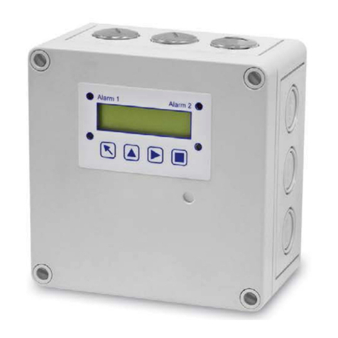
GCE UNISET User manual

UNISET, UNISET+, DINSET, HF SET
OUTLET POINTS FOR INDUSTRIAL USE EN
ENTNAHMESTELLEN FÜR TECHNISCHE GASE DE
POINT D’UTILISATION A USAGE INDUSTRIEL FR
PUNTOS DE CONSUMO PARA USO INDUSTRIAL ES
PUNTI DI PRESA PER L’USO INDUSTRIALE IT
UTTAGSPOST FÖR INDUSTRIELLA APPLIKATIONER SE
ODBĚRNÁ MÍSTA PRO PRŮMYSLOVÉ ÚČELY CS
VÉTELI HELYEK IPARI ALKALMAZÁSRA HU
PUNKTY POBORU DO ZASTOSOWAŃ PRZEMYSŁOWYCH PL
INSTRUCTION FOR USE
BETRIEBSANLEITUNG
MODE D’EMPLOI
INSTRUCCIONES PARA EL USO
MANUALE D´USO
BRUKSANVISNING
NÁVOD K POUŽITÍ
HASZNÁLATI ÚTMUTATÓ
INSTRUKCJA UŻYCIA

— THIS PAGE IS INTENTIONALLY LEFT BLANK —

— THIS PAGE IS INTENTIONALLY LEFT BLANK —
CONTENT
ENGLISH ................................................... 4
DEUTSCH .................................................. 12
FRANÇAIS ................................................. 20
ESPAÑOL .................................................. 28
ITALIANO .................................................. 36
SVENSKA .................................................. 44
ČEŠTINA ................................................... 52
MAGYAR ................................................... 60
POLSZCZYZNA............................................. 68

4/76
EN
ENGLISH
INSTRUCTION FOR USE: OUTLET POINTS FOR INDUSTRIAL USE
FOREWORD
The product complies with the essential requirements of standards for central-gas supply equipment relating to
industrial and technological processes.
Handling of technical gases requires the knowledge of technical standards, rules and directives for compressed,
liqueed and high pressure dissolved gases with regards to the following directives:
• PED 97/23/EC European Pressure equipment directive.
• ISO 7291 Gas welding equipment – Pressure regulators for manifold systems used in welding, cutting and
allied processes up to 300bar.
• ISO 14114 Gas welding equipment – Acetylene manifold systems for welding, cutting and allied processes –
General requirements
• ISO 15615 Gas welding equipment – Acetylene manifold systems for welding, cutting and allied processes –
Safety requirements in high-pressure devices.
• EN 730-1 Gas welding equipment. Safety devices. Incorporating a ame (ashback) arrestor
• ISO 5175-1 Gas welding and cutting equipment and allied processes -- Safety devices for fuel gases and
oxygen or compressed air -- Part 1: General specications and requirements
• ISO 9090 Gas tightness of equipment for gas welding and allied processes.
• ISO 9539 Gas welding equipment – Materials for equipment used in gas welding, cutting and allied processes.
• National rules, directives, norms and regulations must also be complied with.
INTENDED USE
The outlet points are used for industrial applications.
OPERATIONAL, TRANSPORT AND STORAGE REQUIREMENTS
Keep the product and its associated equipment from:
• heat sources (re, cigarettes,...),
• ammable materials,
• oil or grease (especially be careful in use of hand cream)
• water
If the outlet point is stored at temperatures below -20°C do not use the manifold until its temperature reaches
at least -20°C.
National laws, rules and regulations for compressed gases, accident prevention and environmental protection
must be observed.
OPERATION CONDITIONS STORAGE AND TRANSPORT CONDITIONS
20/+60 °C 40/+60 °C
10/100% 10/100%
KEEP DRY! KEEP DRY!
KEEP AWAY FROM OIL AND
GREASE!
KEEP AWAY FROM OIL AND
GREASE!
1.
2.
2.
3.

5/76
EN
PERSONNEL INSTRUCTIONS AND TRAINING
The product distributor shall ensure that all users and persons handling the product are fully trained to carry out
that operation. Trainees need to be supervised by an experienced person.
safety Requirements:
• Read this instruction before installing, or using, the product. Always follow this instruction. The product shall
only be used for the purposes described in this instruction.
• The product must not, under any circumstances be modied by other than the manufacturer.
• Only GCE authorised personnel can maintain the product.
• Installation of the equipment must be only done by qualied personnel in accordance with local directions,
rules and standards.
Gas installations must only be operated by qualied personnel instructed in:
• This operating instruction.
• The special hazards of working with high pressure gases.
• Health and Safety instruction in the use of safety equipment.
• Consequential risk management of accidents and product malfunction.
Contact GCE if further information is required on GCE product training programmes.
PRODUCT DESCRIPTION
UNISET
• Variants for oxygen and fuel gases are equipped with three function ashback arrestors (FBA).
• Oxy/Inert variant is ready for oxygen service and can be used also for argon, nitrogen, helium carbon dioxide,
compressed air and their mixtures. Special oxygen variant as well as acetylene and propane variants contain
FBA. Fuel gas variant is designed for hydrogen, methane and natural gas.
• There are two design types for shielding gases (Ar and Ar-mixtures). First of them consists of ow-gauge
showing ow-rate adjusted by pressure regulator. The second one is based on ow-meter with dosing valve
giving and showing exact ow-rate.
• Components of entire range are mounted on stabile steel wall bracket ensuring fast and safety installation.
• Special twin-variant enable connection of two welding generators at one outlet pipe. This can be used also for
combination of welding and root shielding with identical gas. Flow variant for N2/H2 and Ar/H2 with outlet
capacity of 50l/min is optimal for root shielding application.
• UNISET SINGLE BV contains ball valves, inlet and outlet nipples, wall bracket, hose nipple + nut.
GAS PRESSURE RANGE:
Uniset single BV ODNCO2 - OXY 0 - 30 bar
- DNCO2 0 - 40 bar
Uniset single BV BV+FBA Oxygen - OXY 0 - 15 bar
Uniset single BV + FBA Fuel gases - Acetylene 0 - 1,5 bar
- Hydrogen 0 - 3,5bar
- PM 0 - 5 bar
UNISET+
• Excellent protection, given by the external removable steel cover.
• All variants include inlet brazing socket for 8 mm tube and outlet hose nipple.
• Oxygen, acetylene and fuel gas version contain also pressure gauge and outlet safety device MV93
• Two variants available - one with ow-gauge, second with ow-meter with dosing valve.
DINSET
• consists of inlet welding or brazing socket (acc. to gas type), inlet ball valve PN40, DIN-line regulator with
pressure gauge, ow gauge or ow-meter and hose nipple.
• Components are mounted on V-prole steel wall bracket for safety installation.
• Oxygen variant as well as acetylene and propane variants are prepared for optional installation of GCE
ashback arrestor FR50 due to identical outlet/inlet angle (other variants of ashback arrestors also possible
to install according to product market).
4.
5.

6/76
EN
HF- SET
• outlet points for high ow applications.
• based on two regulators: S100 regulator is prepared for oxygen, acetylene and propane (this can be also
used for natural gas) - optionally can be equipped with ashback arrestor GVA 90 or GVO 90; S200 regulator
is designed for oxygen valve.
5.1. SCHEMATIC PICTURES
2
Uniset
1
10
4
3
8
12
6
7
9
Uniset ow
1
5
3
6
7
2
10
8
9
Uniset+ Oxygen
1
2
11
8
3
4
10
7
12
1
2
9
10
8
7
3
11
5
Uniset+ Argon/CO2
12
Uniset single BV Oxygen
1
2
11
10
6
7

7/76
EN
Description
1. Inlet Connection
2. Ball Valve
3. Adjusting Handwheel
4. Gauge
5. Flowmeter
6. Outlet connection
7. Hose Nipple
8. Regulator
9. Bracket / Holder
10. Mounting holes
11. Cover holder
12. Cover
13. Flashback arrestor
7
DINSET single unit
1
2
9
10
8
4
3
6
6
DINSET FLOW
1
2
9
10
8
5
3
7
6
1
2
9
10
4
7
8
3
HF SET - Type S200
HF SET - Type 100
7
1
2
9
10
8
4
3
6
Uniset single BV Oxygen
1
2
11
10
6
7
13

8/76
EN
5.2. MARKING
5.3. TECHNICAL DATA
DINSET UNISET UNISET + HF SET
Regulator body and bonnet Brass
Diaphragm EPDM, NBR NBR
Seat sealing PA, Chloroprene NBR
Connectors & ttings Brass
Wall bracket Steel Zn-coated Stainless steel Zn Coated
21 3 4 5 4 3
21 3 5 4
5 4 3 2
3
2
5
36 5 2 4
DINSET
UNISET
UNISET +
HF SET
Description
1. Type of regulator
2. Type of gas
3. Max. inlet pressure (P1)
4. Inlet pressure (P2)
5. Date of Manufacture
6. Outlet ow(Q1)
Manufacturers Symbol
of Gas Identication (in
accordance with ISO
7291)
AIR Air
HHydrogen
DAir
AAcetylene
CO2Carbon Dioxide
YMPS
EEthylene
PPropane of LPG
FFuel Gas or Fuel Gas
Mixture
NNitrogen, Inert Gas
LPropylene
MNatural Gas, Methane

9/76
EN
DINSET UNISET UNISET + HF SET
Max. Inlet pressure 30 bar Oxygen
Max. Inlet pressure 40 bar Other gases
Flashback arrestor - Brass-Ni-coated -
Cover - - Stainless steel -
INSTALLATION AND OPERATING INSTRUCTIONS
6.1. GENERAL INSTRUCTIONS
• Failure to comply fully with the instructions in this IFU may result in: injury, death, damage to property, or
equipment, and may invalidate claims that result from the misuse or malfunction of the apparatus.
• The outlet point unit has been leak tested by the manufacturer. All gaskets supplied with the outlet point unit
must be used in the installation. After installation the complete system must be leak tested, to check for any
leaks which may have been caused in transit, or during the installation process.
• Tighten all connections carefully. Low pressure components should be tightened to a torque of 15-20 Nm.
• Keep all components free from oil and grease.
• Hands, tools, work clothes, and all other material used must also be free from oil and grease before and during
installation.
• Check that sealing faces are clean and undamaged. Do not install components with damaged sealing faces or
gaskets.
• Connect the outlet point connections with pre-installed pipework without stressing the outlet point unit.
Stress can cause leakage, malfunction.
6.2. INSTALLATION INSTRUCTIONS
1. Prior installation, or replacement of the outlet point, the system to which it is being installed must be shut
down and all pressure evacuated.
2. Connect the brazing connection (1) the main pipework.
3. Fix the holder to the wall using the mounting holes (10).
4. In case you install the outlet point first and then the pipework, fix the holder to the wall first (point 3) and then
connect brazing connection to pipework (point 2).
5. UNISET+ only: Place the cover (12) on the 4 cover holders (11) premounted to the base plate. Move the cover
down to lock it at the holders as demonstrated on the picture.
OPERATOR INSTRUCTIONS Safety Instructions
Operating instructions must be accessible and kept close to the equipment.
Personnel using the equipment must have been trained how to operate the high pressure valve unit system.
Always follow the environmental, cleanliness and safety guidelines for working with high pressure oxygen.
The equipment should be kept free from of oil or grease. Always wash your hands prior to handling the high
pressure valve unit or the cylinder.
In the outlet point area, no smoking, naked lights, cigarettes, or storage of ammable materials is permitted.
Protect the outlet point from dust, water, and caustic/toxic environments which could be detrimental to the
product.
If the operator suspects or is aware that the product is damaged or malfunctioning, its use must be ceased
immediately, and the supplier/authorised agent must be contacted.
Check that all ventilation grills are free from obstruction and that the extraction system (when installed) is
functioning correctly.
Only persons trained in safety in the workplace and accident prevention may operate the equipment.
Personnel must also have basic safety knowledge regarding the gases that are being used.
The equipment must be examined regularly to make sure that it is working correctly and that there is no gas
leakage.
Replace all worn or damaged parts with original spare parts. Gaskets, O-rings, and sealing surfaces must be
clean and free from damage to work eectively.
5.
6.
7.

10/76
EN
For safety reasons all shut-o valves should to be opened slowly and smoothly. Shut-o valves can be fully
open after inlet and outlet pressures are balanced and after a leak tight check of all connections.
Ensure only the correct gas supply is connected to the outlet point. (see chapter 5.3.) Connection of the
incorrect gas supply could lead to explosion or re, causing personnel injury and damage to property.
7.1. CHECKS BEFORE OPERATING
Before use it must be ensured that:
• The outlet point is securely installed.
• All connections are tight with no leakage. When using leak detection uid, protect the internal parts of the
outlet point from entering of uid as this will be detrimental to the long term function of the outlet point
• The complete system has been purged with inert gas.
• Ball valve (2) is closed and the pressure adjusting handwheel (3) is screwed fully out.
7.2. USE OF THE GAS FROM OUTLET POINT
• Connect hose from the installed application equipment to the hose nipple (7).
• Slowly open the ball valve (2) until it is fully open.
• Regulate the gas pressure to your process requirements by rotating the adjusting handwheel (3) and
observing the gauge (4) or ow-meter (5).
7.3. SWITCHING OFF
• Close the ball valve (2).
• Unscrew the adjusting handwheel (3) to fully open.
LIFETIME
• The outlet tapping point has a lifetime of 10 years. After end of the lifetime, complete outlet point should be
disposed o.
SERVICE AND MAINTENANCE
• The outlet point should be inspected regularly for damage or leakage. All connections and seals must be leak
tested every 6 months, at least, or as deemed necessary by local working practices.
• All threaded connections and exible lines need to be checked after an appropriate period of time in
accordance with local operating conditions, but must be inspected at least once yearly.
• Regulators, safety valves, lters and exible hoses contain parts made from plastics, elastomers and other
exible materials. In time they may degrade through exposure to excessive temperature variation, UV-
radiation and excessive use in harsh working environments. It is therefore recommended that these parts are
replaced after 5 years. Local standards codes of practice and guidelines should be followed.
• All inspections and tests must be documented, in line with local quality/safety management systems.
• Only GCE authorised service agents may service or repair the manifold. Contact GCE Technical Service for
further information about service available in your area.
• For warranty claims contact sales representative or installation company.
PRODUCT DISPOSAL RECYCLING
Prior to disposal the outlet point must be purged of any residues of toxic material. The outlet point must be
disposed of through a licensed waste disposal agent, not as general municipal waste. It is also good working
practice and commercially benecial that the outlet point is dismantled and segregated into metallic parts
(ferrous and non ferrous) and non metallic parts (plastics, elastomers etc) for recycling prior to disposal.
8.
9.
10.

11/76
EN
Manufactured by:
GCE s.r.o. Tel: 00420 569 661 111
Zizkova 381 Fax: 00420 569 661 602
583 81 Chotebor http://www.gcegroup.com
Czech Republic © GCE s.r.o.
GLOSSARY
Caution Inlet features
Keep dry Outlet features
Upper and lower temperature limit REF Product part number
Upper and lower humidity limit Keep away from heat and
ammable material
QOutlet ow Keep away from oil and grease
P1Inlet pressure range Consult operating instructions
P4Max Outlet pressure (Closing pressure) P2Outlet pressure
Return equipment for recycling.
According to WEEE 2002/96/EG
directive. Do not dispose of into
unsorted municipal waste.
SN
Product serial number
M YY XXX
M: Manufacturing date
Y: Manufacturing year
X: Production number
WARRANTY
The Standard Warranty period is two years from date of receipt by the GCE Customer (or if this is not known 2
years from time of the product manufacture shown on the product).
The standard warranty is only valid for products handled according to Instruction for use (IFU) and general
industry good practice and standards.
11.
12.

12/76
DE
DEUTSCH
BETRIEBSANLEITUNG: ENTNAHMESTELLEN FÜR TECHNISCHE GASE
VORWORT
Dieses Produkt erfüllt die einschlägigen Standards für zentrale Versorgungsanlagen insbesondere mit
technischen Gasen in der Industrie, sowie anderen Anwendungsbereichen in welchen technische Gase zur
Anwendung kommen.
Der Umgang mit Druckgasen erfordert die Sachkenntnis von Normen, technischen Regeln und Vorschriften für
verdichtete, üssige und gelöste Gase.
• PED 97/23/EC Europäische Druckgeräte-Richtlinie (European Pressure equipment directive).
• ISO 7291 Gasschweißgeräte - Hauptstellendruckregler für Schweißen, Schneiden und verwandte Prozesse bis
30 MPa (300 bar)
• ISO 14114 Gasschweißgeräte - Acetylenaschen-Batterieanlagen für Schweißen, Schneiden und verwandte
Verfahren - Allgemeine Anforderungen.
• ISO 14113 Gasschweißgeräte – Kunststoschläuche und Schlauchleitungen für industrielle Gase bis zu einem
Druck von 450 bar
• ISO 15615 Gasschweißgeräte - Acetylenaschen-Batterieanlagen für Schweißen, Schneiden und verwandte
Prozesse - Sicherheitsanforderungen für Hochdruckeinrichtungen
• EN 730-1 Gasschweißgeräte - Sicherheitseinrichtungen - Teil 1: Mit integrierter Flammensperre
(“Trockenvorlage”)
• ISO 5175-1 - Einrichtungen für Gasschweißen, Schneiden und verwandte Verfahren. Sicherheitseinrichtungen
für Brenngase und Sauersto oder Druckluft. Allgemeine Festlegungen, Anforderungen, Prüfungen.
• ISO 9090 Schweißen. Gasdichtheit von Geräten für Gasschweißen und verwandte Verfahren.
• ISO 9539 Gasschweißgeräte - Werkstoe für Geräte für Einrichtungen zum Gasschweißen, Schneiden und
verwandte Prozesse.
• Es sind auch die nationalen Gesetze, Verordnungen und Normen zu beachten.
BESTIMMUNGSGEMÄSSER GEBRAUCH
Die einzelnen Einheiten sind so vorbereitet, dass sie für alle technischen Gase eingesetzt werden können.
SICHERHEITSANFORDERUNGEN AN BETRIEB,
TRANSPORT UND LAGERUNG
DAS PRODUKT UND DIE ZUGEHÖRIGEN GERÄTE SIND FERNZUHALTEN VON:
• Potentiellen Brandquelle (Feuer, oenes Licht, etc.),
• Brennbaren Materialien,
• Ölen oder Fetten (Vorsicht bei der Anwendung der Handcreme),
• Wasser.
Wenn das Gerät bei der Temperatur unter -20 °C gelagert wird, muss vor Anwendung eine Gerätetemperatur von
-20°C oder höher vorliegen.
Es sind die nationalen Gesetze, Regelungen und Vorschriften zur Unfallverhütung und Umweltschutz beim
Einsatz von Hochdruckgasen zu beachten.
BETRIEBSBEDINGUNGEN LAGER UND
TRANSPORTBEDINGUNGEN
-20/+60 °C -40/+60 °C
10/100% 10/100%
Vor Feuchtigkeit
schützen!
Vor Feuchtigkeit
schützen!
Von Ölen und Fetten
fern halten.
Von Ölen und Fetten
fern halten.
1.
2.
2.
3.

13/76
DE
PERSONNEL INSTRUCTIONS AND TRAINING
Der Betreiber hat sicherzustellen, dass alle Benutzer und Personen, die mit dem Produkt umgehen, ausreichend
geschult sind. Auszubildende sind von einem erfahrenen Mitarbeiter zu beaufsichtigen.
SICHERHEITSVORSCHRIFTEN:
• Lesen Sie bitte die Bedienungsanleitung vor der Installation oder Anwendung und gehen Sie immer gemäß
der Bedienungsanleitung vor.
• Das Produkt darf nur gemäß der bestimmungsgemäßen Verwendung zum Einsatz kommen.
• Am Produkt sind keine Veränderungen oder Umbauten zulässig. Das Produkt darf nur durch den Hersteller
verändert werden.
• Die Wartung und Instandhaltung des Produkts darf nur eine von GCE autorisierte Person vornehmen.
• Die Installation muss von einer qualizierten Person gemäß den örtlichen Vorschriften, Regelungen und
Normen durchgeführt werden.
Qualizierte Personen, die die Installation der Gasanlagen vornehmen, müssen mit folgenden Dokumenten
und Themen vertraut sein:
• Entsprechende Bedienungsanleitungen,
• Information zu Gefahren beim Umgang mit unter Hochdruck gespeicherten Gasen
• Sicherheitshinweise für Arbeiten an sicherheitsrelevanten Bauteilen und Systemen
• Wichtige Unfallverhütungsvorschriften
Informieren Sie GCE falls Bedarf an weiteren Produktschulungen besteht.
PRODUKTBESCHREIBUNG
UNISET
Die Varianten für Sauersto und Brenngase sind mit Sicherheiteinrichtungen (FBA) mit drei Funktionen
ausgestattet.
Die Sauersto-Inertgas-Variante ist bereit für den Einsatz mit Sauersto und kann auch für Argon, Helium,
Kohlendioxid, Druckluft und Mischungen daraus verwendet werden. Eine spezielle Sauerstovariante sowie
Azetylen- und Propan-Varianten verfügen über Flammenrückschlagsicherungen (FBA). Die Brenngas-Variante
ist konzipiert für die Verwendung von Wassersto, Methan- und Erdgas.
Es gibt zwei Ausführungstypen für Schutzgas (Ar und Ar-Mischungen). Die erste Variante besteht aus einer
Durchussanzeige, die Durchussraten anzeigt, welche durch einen Druckregler eingestellt werden können.
Die zweite Variante basiert auf einem Durchussmessgerät mit einem Dosierventil, das exakte Durchussraten
ermöglicht und anzeigt.
Die Komponenten der gesamten Produktreihe werden an einer stabilen Wandhalterung angebracht, die eine
schnelle und sichere Installation ermöglichen.
Eine spezielle Twin-Variante ermöglicht den Anschluss von zwei Schweißgeneratoren an einem Auslassrohr. Dies
kann auch für eine Kombination aus Schweißen und formieren min identischne Gas verwendet werden. Die
Durchussvariante für N2/H2 und Ar/H2 mit einer Durchusskapazität von 50 l/min ist optimal zum formieren.
UNISET SINGLE BV contains ball valves, inlet and outlet nipples, wall bracket, hose nipple + nut.
Gas- und Druck Varianten:
Uniset single BV ODNCO2 - OXY 0 - 30 bar
- DNCO2 0 - 40 bar
Uniset single BV BV+FBA Oxygen - OXY 0 - 15 bar
Uniset single BV + FBA Fuel gases - Acetylene 0 - 1,5 bar
- Hydrogen 0 - 3,5bar
- PM 0 - 5 bar
UNISET+
• Exzellenter Schutz dank der externen Außenabdeckung aus Stahl.
• Alle Varianten verfügen über eine einen einlassseitigen Lötanschluss für eine 8 mm große Leitung und einen
Auslassschlauchstutzen.
• Die Sauersto-, Azetylen- und Brenngas-Varianten verfügen zudem über eine Druckanzeige und die
auslassseitige Schutzvorrichtung MV93.
• Zwei verfügbareVarianten – eine mit Durchussanzeige, die zweite mit Durchussmessgerät mit Dosierventil.
4.
5.

14/76
DE
DINSET
• Verfügt über einen einlasseitigen Schweiß- oder Lötanschluss (abhängig vom Gastyp), das einlassseitige
Kugelventil PN40, DIN-Leitungsregler mit Druckanzeige, Durchussanzeige oder Durchussmessgerät und
Schlauchstutzen.
• Die Komponenten werden auf einer Wandhalterung mit V-Stahlprol für eine sichere Installation befestigt.
• Die Sauersto- sowie Azetylen- und Propan-Varianten sind für die optionale Installation der GCE-
Flammenrückschlagsicherung FR50 vorbereitet, da sie über einen identischen Einlass-/Auslasswinkel
verfügen (Installation anderer Varianten von Flammenrückschlagsicherungen auch möglich, abhängig von
der Produktverfügbarkeit auf dem Markt).
HF- SET
• Auslasspunkte für Anwendungen mit hohem Durchuss.
• Basierend auf zwei Reglern: Der S100-Regler ist für Sauersto, Azetylen und Propan vorbereitet (kann auch
für Erdgas verwendet werden) – kann optional mit den Flammenrückschlagsicherungen GVA 90 oder GVO 90
ausgestattet werden. Der S200-Regler ist für ein Sauerstoventil vorgesehen.
5.1. SCHEMATISCHE DESCRIPTION
2
Uniset
1
10
4
3
8
12
6
7
9
Uniset ow
1
5
3
6
7
2
10
8
9
Uniset+ Oxygen
1
2
11
8
3
4
10
7
12
1
2
9
10
8
7
3
11
5
Uniset+ Argon/CO2
12
Uniset single BV Oxygen
1
2
11
10
6
7

15/76
DE
7
DINSET single unit
1
2
9
10
8
4
3
6
6
DINSET FLOW
1
2
9
10
8
5
3
7
6
1
2
9
10
4
7
8
3
HF SET - Type S200
HF SET - Type 100
7
1
2
9
10
8
4
3
6
Beschreibung
1. Eintrittsanschluss
2. Kugelventil
3. Stellschraube des Reglers (Handrad)
4. Manometer
5. Durchussmesser
6. Ausganganschluss
7. Schlauchnippel
8. Regler
9. Klemme / Halterung
10. Montagelöcher
11. Konsole
12. Deckel
Uniset single BV Oxygen
1
2
11
10
6
7
13

16/76
DE
5.2. KENZEICHNUNG
5.3. TECHNISCHE DATEN
DINSET UNISET UNISET + HF SET
Gehäuse, Haubenmaterial Messing
Membranmaterial EPDM, NBR NBR
Material d. Sitzdichtung PA, Chloroprene NBR
Anschlüsse & Armaturen Messing
Klemme/Halterung Steel Zn-coated Edelstahl Zn Coated
21 3 4 5 4 3
21 3 5 4
5 4 3 2
3
2
5
36 5 2 4
DINSET
UNISET
UNISET +
HF SET
BESCHREIBUNG
1. Reglertyp
2. Gas
3. Max. Eingangsdruck (P1)
4. Eingangsdruck (P2)
5. Herstellungsdatum
6. Outlet Fluss (Q1)
Manufacturers Symbol
of Gas Identication (in
accordance with ISO
7291)
AIR Air
HHydrogen
DAir
AAcetylene
CO2Carbon Dioxide
YMPS
EEthylene
PPropane of LPG
FFuel Gas or Fuel Gas
Mixture
NNitrogen, Inert Gas
LPropylene
MNatural Gas, Methane

17/76
DE
DINSET UNISET UNISET + HF SET
Max. Eingangsdruck 30 bar Sauersto
Max. Eingangsdruck 40 bar Andere Gase
Flashback arrestor - Brass-Ni-coated -
Deckel - - Edelstahl -
INSTALLATIONS UND BETRIEBSANWEISUNG
6.1. ALLGEMEINE HINWEISE
• Das Nichtbeachten dieser Anleitung kann Verletzungen, Tod, Sachschäden als Folge haben und die Garantie
durch nicht bestimmungsgemäße Anwendung ungültig machen.
• Die ganze Einrichtung wurde vom Hersteller auf die innere und äußere Dichtheit geprüft. Alle Dichtungen
werden gemeinsam mit der Anlage mitgeliefert und sind bei der Installation zu verwenden. Nach der
Installation muss das ganze Batteriesystem auf die innere und äußere Dichtheit geprüft werden, die während
des Transports oder der Installation eintreten könnte.
• Alle Verbindungen müssen gasdicht angezogen werden. Die Niederdruckkomponenten mit einem Moment
von 15-20 Nm nachgezogen werden.
• Die Komponenten dürfen nicht mit Öl- und Fett in Kontakt kommen.
• Hände, Arbeitskleidung und alles, was mit dem Gerät bei Installation oder Betrieb in Kontakt kommt, muss
frei von Öl und Fett sein.
• Die Dichtverbindungen sind zu kontrollieren, ob sie sauber und unbeschädigt sind. Die Komponenten mit
beschädigter Dichtung dürfen nie verwendet werden.
• Verbinden Sie die Entnahmestelle-Verbindungen mit vorinstallierten Verrohrung ohne Belastung der
Entnahmestelle. Stress kann zu Undichtigkeiten, Fehlfunktion.
• Schließen Sie niemals für bestimmte Gasart bezeichnet Entnahmestelle zu anderen Gastyp bezeichnet
Verrohrung (Details über die richtige Art des Gases kann auf dem Kennzeichnungs gefunden werden - Kapitel
4).
6.2. MONTAGEANLEITUNG
1. Vor der Installation oder den Austausch der Entnahmestelle, das System auf die er installiert wird muss ge-
schlossen werden, und alle Druck evakuiert.
2. Verbinden Sie das Eintrittsanschluss (1) mit der Hauptrohrleitungen.
3. Befestigen Sie den Halter vermittels der Montagelöcher (10) an der Wand.
4. Falls Sie die Entnahmestelle zuerst und dann Verrohrung zu installieren, befestigen Sie den Halter an die Wand
zuerst (Punkt 3) und dann verbinden Sie die Entnahmestelle an der Verrohrung (Punkt 2).
5. UNISET +: Legen Sie die Abdeckung (12) auf den 4 Deckel-Halter (11) vormontiert auf den Deckel. Bewegen Sie
die Abdeckung nach unten, um es an den Halter zu verriegeln, wie im Bild gezeigt.
BETRIEB
7.1. SICHERHEITSHINWEISE
Die Bedienungsanleitung muss in der Nähe des Geräts aufbewahrt und immer gribereit sein.
Personen, die mit dem Gerät umgehen, müssen zu diesem Zweck ordentlich eingeschult sein.
Es sind die Vorschriften zu Unfallverhütung und Umweltschutz beim Einsatz von Hochdrucksauersto zu
beachten.
Das Gerät darf nicht mit Öl- und Fett in Kontakt kommen. Vor jedem Umgang mit dem Gerät oder der
Gasquelle Hände waschen.
In der Umgebung ist es verboten, zu rauchen, mit oenem Feuer zu manipulieren oder brennbares Material
zu lagern.
Das Gerät vor Staub, Wasser, Ätzmitteln und toxischen Stoen schützen, die das Produkt beschädigen
können.
Wenn eine Beschädigung oder fehlerhafte Funktion festgestellt wird, ist das Produkt sofort außer Betrieb zu
setzen und der Lieferant oder autorisierte GCE-Person sind zu kontaktieren.
5.
6.
7.

18/76
DE
Wenn sich das Gerät innerhalb eines Gebäudes bendet, überprüfen Sie, ob alle Entlüftungsönungen frei
von Hindernissen sind. Überprüfen Sie die richtige Funktion des Entlüftungssystems, falls vorhanden.
Mit dem Gerät dürfen nur Personen verändern, die über Arbeitssicherheit eingeschult sind. Das Personal
muss mindestens die Grundkenntnisse über Arbeitssicherheit bezüglich Gase haben, mit denen es arbeitet.
Das Gerät muss regelmäßig kontrolliert werden, um die richtige Funktion zu gewährleisten und mögliche
Leckage zu verhüten.
Alte oder beschädigte Teile sind ausschließlich gegen Originalersatzteile zu ersetzen (Dichtung, O-Ringe).
Die Dichtungsoberächen müssen immer sauber und ohne Beschädigung sein, um die richtige Funktion zu
gewährleisten.
Aus Sicherheitsgründen sollten alle Absperrventile langsam geönet werden. Die Absperrventile können
erst Überprüfung aller Verbindungen auf Dichtheit voll geönet werden.
Überprüfen Sie, dass das Gerät mit der richtigen Gasart verbunden ist. Der Anschluss einer unrichtigen
Gasquelle kann die Explosion oder Feuer verursachen, was Personen und Sachschäden als Folge hat.
Beachten Sie die Kennzeichnung am Gerät und/oder Regler, um den richtigen Gastyp zu ermitteln (siehe
Kapitel 5.3).
7.2. ÜBERPRÜFUNGEN VOR DER INBETRIEBNAHME
Before use it must be ensured that:
• Die Entnahmestelle ist sicher installiert.
• Alle Verbindungen sitzen fest, es bestehen keine Leckagen. Als Sie die Leckanzeigeüssigkeit verwenden,
schützen Sie die inneren Teile der Entnahmestelle gegen Eindringen von Flüssigkeiten, da dies schädlich für
die langfristige Abhängigkeit von der Entnahmestelle sein.
• Das Kugelventil (2) ist geschlossen und die Stellschraube des Reglers (Handrad) (3).
7.3. VERWENDUNG DES GASES VON ENTNAHMESTELLE
• Verbinden Sie den Schlauch von der installierten Anwendung Geräte an den Schlauchnippel (7).
• Önen Sie langsam das Kugelventil (2), bis sie vollständig geönet ist.
• Stellen Sie den Gasdruck an Ihre Prozessanforderungen durch Drehen des Handrad (3) und Regeln des
Manometers (4) oder der Druckmesser (5).
7.4. AUSCHALTEN
• Schließen Sie das Kugelventil (2).
• Drehen Sie die Stellschraube des Reglers (3) auf.
LEBENSDAUER
• Die maximale Lebensdauer der Entnahmestelle beträgt 10 Jahre. Nach dem Ende der Lebensdauer sollte
vollständige Entnahmestelle entsorgt werden.
SERVICE UND WARTUNG
• Die Anlage auf mögliche Undichtheiten und Systembeschädigungen regelmäßig kontrollieren. Die Kontrolle
aller Verbindungen und Dichtungen muss minimal alle sechs Monate oder häuger gemäß den betrieblichen
Beanspruchungen, den nationalen Vorschriften sowie den Empfehlungnen gemäß dem DVS Merkblatt 0221
vorgenommen werden.
• Alle Gewindeverbindungen und Schlauchanschlüsse müssen gemäß den festgelegten Arbeitsvorschriften
geprüft werden, mindestens aber einmal jährlich.
• Druckregler, Trockenvorlagen, Filter enthalten Bestandteile aus Kunststo, Elastomeren und anderen
Werkstoen, die im Laufe der Zeit ihre Qualität und Eigenschaften infolge großer Temperaturänderungen,
UV-Strahlung und Anwendung im rauen Klima verlieren können.
• Es wird deshalb empfohlen, oben genannten Armaturen alle 5 Jahre zu ersetzen. Auch die örtlichen Normen
und Vorschriften sollten erfüllt und praktische Erfahrungen im Wartungszyklus berücksichtigt werden.
• Alle Kontrollen und Prüfungen müssen im örtlichen Prüfbuch des Qualitäts- und Sicherheitssystem
eingetragen werden.
• Nur von GCE autorisierte Personen dürfen die Wartung und Instandsetzung des Systems durchführen.
Setzen Sie sich mit dem Technischem GCE Service in Verbindung, um mehrere Informationen über mögliche
Serviceleistungen in Ihrer Region zu erhalten.
• Für Reklamationen setzten Sie sich mit dem Verkaufshändler oder der Installationsrma in Verbindung.
8.
9.

19/76
DE
Hersteller:
GCE s.r.o. Tel: 00420 569 661 111
Zizkova 381 Fax: 00420 569 661 602
583 81 Chotebor http://www.gcegroup.com
Czech Republic © GCE s.r.o.
PRODUKTRECYCLING
Vor dem Recycling des Produkts muss das Restgas und toxisches Material entfernt werden. Das System ist in einer
Sammelstelle zu entsorgen, nie als Kommunalmüll. Es ist empfehlenswert und günstig, eine Materialtrennung
vor dem endgütigen Recycling vorzunehmen.
Das Produkt ist gemäß den örtlichen Vorschriften und der Norm WEEE 2002/96/EG zu entsorgen, wenn als
Zubehörteile Kontaktmanometer oder Gasvorwärmer montiert sind.
ZEICHENERKLÄRUNG
Vorsicht! Eingangsfunktionen
Vor Feuchtigkeit schützen! Ausgangsfunktionen
Untere und obere Temperaturgrenze. REF Artikelnummer
Untere und obere Feuchtigkeitsgrenze Von Hitze und Flammen fernhalten
QAusgangsdurchuss Von Öl und Fett femhalten
P1Eingangsdruck Bedienungsanleitung ansehen
P4Max. Ausgangsdruck (Schließdruck) P2Ausgangsdruck
Das Produkt ist gemäß der Norm WEEE
2002/96/EG zu rezyklieren. Nicht in
ungetrennten Kommunalmüll werfen.
SN
Produktseriennummer
M JJ XXXXX
M: Herstellungsmonat
J: Herstellungsjahr
X: Produktionsnummer
GEWÄHRLEISTUNG
Die Standard Garantiezeit beträgt zwei Jahre ab dem Datum des Warenempfangs beim GCE Kunden (oder falls
das nicht ermittelbar ist, ab dem Produktionsdatum welches auf der Ware ausgewiesen ist.)
Die Standard Garantiezeit ist nur gültig für Waren, die entsprechend der Bedienungsanleitung und der generell
gültigen Praxis und Normen der Industrie gehandhabt wurden.
10.
11.
12.

20/76
FR
FRANÇAIS
MODE D’EMPLOI : POINT D’UTILISATION A USAGE INDUSTRIEL
AVANTPROPOS
Le produit est conforme aux normes relatives aux équipements pour les systèmes de distribution de gaz
centralisés .
La manipulation avec les gaz techniques comprimés nécessite la connaissance des normes techniques, règles et
directives pour les gaz sous pression, liquides et dissous conformément aux normes suivantes:
• PED 97/23/EC La directive européenne sur la sécurité des matériaux utilisés dans les équipements sous
pression (European Pressure equipment directive).
• ISO 7291 Matériel de soudage aux gaz – Détendeurs de centrale de bouteilles pour le soudage, le coupage
et les techniques connexes jusqu’à 30 MPa (300 bar) Dispositifs de sécurité pour les gaz combustibles et
l’oxygène ou l’air comprimé. Spécications et exigences générales et essais.
• ISO 14114 Matériel de soudage aux gaz -- Centrales de détente pour la distribution d’acétylène pour le
soudage, le coupage et les techniques connexes -- Exigences générales.
• ISO 15615 Matériel de soudage aux gaz -- Centrales de détente pour la distribution d’acétylène pour le
soudage, le coupage et les techniques connexes -- Exigences de sécurité pour les dispositifs haute pression
• EN 730-1 Matériel de soudage aux gaz - Dispositifs de sécurité - Partie 1 : avec arrêt de amme (“Anti retour”)
• ISO 5175-1 - Équipements de soudage au gaz, de coupage et procédés connexes – Dispositifs de sécurité pour
les gaz combustibles et l’oxygène ou l’air comprimé – Spécications et exigences générales et essais.
• ISO 9090 Soudage. Étanchéité aux gaz des appareils pour soudage aux gaz et techniques connexes.
• ISO 9539 Matériel de soudage aux gaz -- Matériaux utilisés pour le matériel de soudage aux gaz, coupage et
techniques connexes.
• Il faut respecter les lois, les règlements et normes locales.
UTILISATION
Le point de sortie est a usage industriel.
EXIGENCES DE SECURITE DEXPLOITATION, TRANSPORT ET STOCKAGE
Tenir le produit, y compris ses accessoires, hors des:
• sources de chaleur (feu, cigarettes, ...),
• matières inammables,
• huile ou graisse (attention si vous utilisez de la crème à mains),
• eau.
Si le point de sortie est stocké sous température inférieure à -20 °C, sa température avant utilisation doit atteindre
au moins -20°C.
Il faut respecter les lois, les règlements et autres arrêtés sur les gaz comprimés, la sécurité du travail et la
protection de l´environnement.
CONDITIONS D’UTILISATION CONDITIONS DE STOCKAGE ET DE
TRANSPORT
-20/+60 °C -40/+60 °C
10/100% 10/100%
Tenir au sec! Tenir au sec!
Ne peut entrer en contact avec
l’huile et lubriants huileux.
Ne peut entrer en contact avec
l’huile et lubriants huileux.
1.
2.
2.
3.
This manual suits for next models
4
Table of contents
Languages:
Other GCE Controllers manuals
