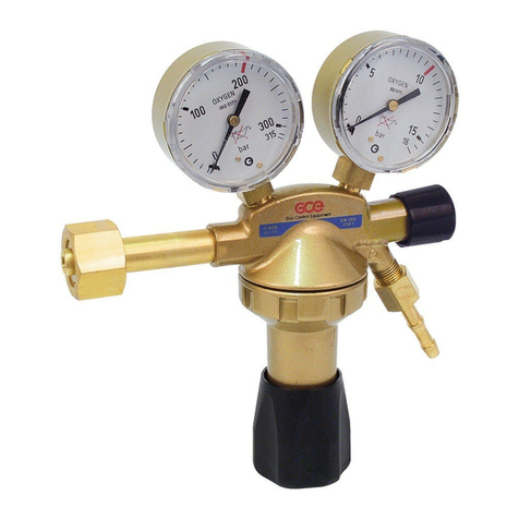
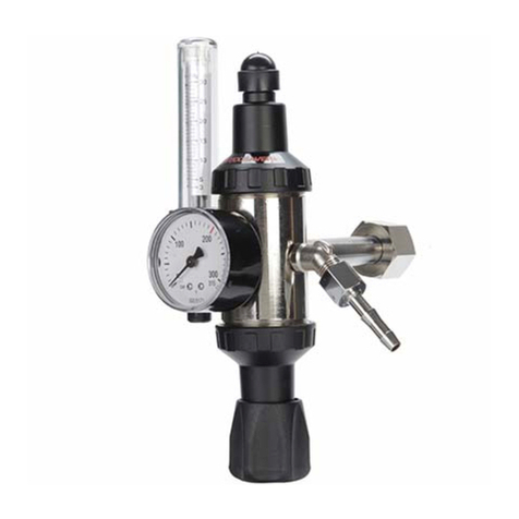
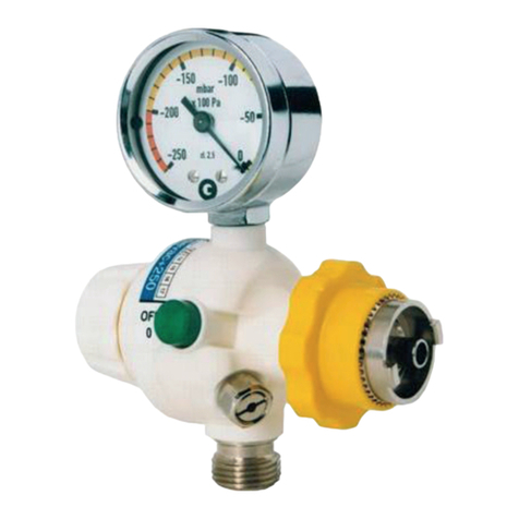
GCE MEDISELECT II User manual

GCE HEALTHCARE
HIGH PRESSURE REGULATORS; INSTRUCTION FOR USE
DRUCKMINDERER; BEDIENUNGSANLEITUNG
DÉTENDEURS HAUTE PRESSION; MANUEL D´UTILISATION
HOGEDRUK REDUCEER VENTIELEN; GEBRUIKSAANWIJZING
PALACKNYOMÁSCSÖKKENTŐK; HASZNÁLATI ÚTMUTATÓ
VYSOKOTLAKÉ REDUKČNÍ VENTILY; NÁVOD K POUŽITÍ
WYSOKOCIŚNIENIOWE ZAWORY REDUKCYJNE;
INSTRUKCJA OBSŁUGI
;
ИНСТРУКЦИЯ ПО ЭКСПЛУАТАЦИИ
REGULADORES DE ALTA PRESIÓN; INSTRUCCIONES DE USO
REDUTORES DE PRESSÃO; INSTRUÇÕES DE UTILIZAÇÃO
RIDUTTORI DI PRESSIONE; MANUALE D´USO
HÖGTRYCKS REDUCERINGSVENTILER;
ANVÄNDARANVISNING
HØYTRYKKREDUKSJONSVENTILER; BRUKSANVISNING
HØJTRYKEGULATORER; BRUGERVEJLEDNING
PAINEENALENNUSVENTTIILIT; KÄYTTÖOHJE
AUGSTSPIEDIENA REDUKCIJAS VĀRSTI;
LIETOŠANAS PAMĀCĪBA
AUKŠTO SLĖGIO REDUKCINIAI VENTILIAI;
NAUDOJIMOSI INSTRUKCIJA
KÕRGE SURVEGA REDUKTORVENTIILID; KASUTUSJUHEND
MEDISELECT® II, MEDIREG® II
EN
DE
CS
PL
RU
FR
ES
PT
IT
SV
NL
NO
DA
FI
HU
LV
LT
ET

A
B
C
D
E
F
FIG. 1
E
A
B
FIG. 2

3/195
EN
1. FOREWORD
GCE Medical Regulators are medical devices classified as class IIb
according to the Medical Device Directive 93/42/EEC.
Their Compliance with essential requirements of 93/42/EEC Medical Device
Directive is based upon EN 10524-1 standard.
2. INTENDED USE
GCE Medical Regulators are designed for use with high-pressure medical
gas cylinders equipped with a medical cylinder valve. They regulate
pressure and flow of medical gases to the patient. They are intended
for the administration of the following medical gases in the treatment,
management, diagnostic evaluation and care of the patient:
• Oxygen;
• Nitrous oxide;
• Air for breathing;
• Helium;
• Carbon dioxide;
• Xenon;
• Specified mixtures of the gases listed.
• Air or nitrogen to power surgical tools.
3. OPERATIONAL, TRANSPORT AND STORAGE
SAFETY REQUIREMENTS
Keep the product and its associated equipment away from:
• All sources of heat,
• Flammable materials,
• Oil or grease (including all hand creams),
• Water,
• Dust.
The product and its associated equipment must be prevented from falling
over.
Always maintain oxygen cleanliness standards,
Use only the product and its associated equipment in a well ventilated
area.
ENGLISH
INSTRUCTION FOR USE: MEDIREG® II, MEDISELECT® II

4/195
EN
Before initial use the product should be kept in its original packaging. GCE
recommends use of the original packaging (including internal sealing bag
and caps) if the product is withdraw from operation (for transport, storage).
Statutory laws, rules and regulations for medical gases, accident prevention
and environmental protection must be observed.
OPERATING CONDITIONS STORAGE AND TRANSPORT
CONDITIONS
-20/+60 °C -30/+60 °C
10/100% 10/100%
600/1200 mbar 600/1200 mbar
In case of storage at a temperature below -20 °C, d o not operate the re-
gulator until it has been allowed to increase its temperature to a minimum
of -20 °C.
At regulators intended for use with mixture of medical gases O2+N2O is
lower operation temperature limit +5°C. During normal use the flow outlet
and pressure outlet will sometimes have a frosty appearance. This is a
normal physical reaction in the valve, due to that the gas is going from
high pressure to low pressure (Joule Thompson eect). Ensure that all
equipment that is connected to the valve by at least a 2 metre hose.
4. PERSONNEL INSTRUCTIONS
The Medical Devices Directive 93/42/EEC states that product provider
must ensure that all personnel handling the product are provided with the
operating instructions & performance data.
Do not use the product without properly familiarization of the product and
its safe operation as defined in this Instruction for use. Ensure user is awa-
re of particular information and knowledge required for the gas in use.
5. PRODUCT DESCRIPTION
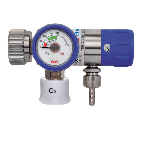
FIG. 1: Typical configuration of MediSelect®II regulator
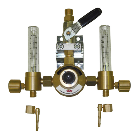
FIG. 2: Configuration of MediReg® II regulator with flowmeter
The regulator acts as a pressure-reducer, gas from the cylinder valve
passes through the pressure regulator to the user outlets.
A INLET STEM
Regulator is fitted to the medical cylinder valve by mean of an inlet stem.
The stem can be bull nose type (male thread), nut type (female thread) or
pin index type. The inlet stem includes a filter.

5/195
EN
B INLET PRESSURE INDICATOR OR SENSOR
The regulator is fitted with a pressure indicator or sensor which is intended
for cylinder gas content indication only, not for measuring purposes. The
pressure indicator or sensor can be equipped with output of electric signal.
The connection of pressure indicator with output of electric signal must be
carried out by trained personnel in accordance with national regulations
pertaining to the electric device and standard EN ISO 7396-1.
Output of electric signal shall be connected only to device which is in
accordance with standard EN ISO 60601-1 and 60601-1-2.
C, D, E FLOWMETERING DEVICE AND FLOW OUTLET
GCE regulators can be supplied with a flow-metering device - flow control
head “C” or flowmeter “D”. This function is used to supply a gas flow (l/min)
at atmospheric pressure directly to the patient through the flow outlet “E”,
e.g. through a cannula or a facemask.
The flow outlet “E” can be hose nipple (for cannula or mask) or outlet with
thread (for humidifier).
F PRESSURE OUTLET
The regulator may be fitted with a pressure outlet. The pressure outlet is the
outlet directly from the low-pressure chamber. Two types of the pressure
outlet can be used:
Pressure outlet I - is fitted with a gas specific medical quick connector also
called “quick coupler” . The user can connect another piece of equipment
to this outlet with a gas specific male probe. The quick connector self seals
when the male probe is disconnected. This outlet is for supplying gas at a
controlled pressure to power medical devices, e.g. medical ventilator.
Pressure outlet II – is fitted with a threaded connector. The regulator with
this type of pressure outlet shall be only an integral part of a medical
equipment (e.g. emergency ventilators, anaesthesia devices, etc.)
If the regulator is fitted with two pressure outlets, do not use both of them
at the same time. If you use both of them in the same time the performan-
ce of the regulator will not be according to specification (see appendix 1) !!!
Note also that the product colour (especially flow control knob) might not
be gas specific colour coded.
6. OPERATIONS
6.1. BEFORE USE
6.1.1. VISUAL INSPECTION BEFORE USE
• Check if there is visible external damage to the product (including product
labels and marking) and on the gas cylinder. If it shows signs of external
damages, remove it from service and identify its status.
• Visually check if the product or the medical gas cylinder is contaminated;
if needed, for the regulator, use the cleaning procedure detailed in this
section (if required for the cylinder, refer to the gas cylinder manufacturer
cleaning recommendation).

6/195
EN
• Check that the total life time of the product and the gas cylinder has not
been exceeded, (refer to GCE or owner’s date coding system). If life time
has been exceeded, remove the product (or the gas cylinder) from service
& suitably identify its status.
• Ensure that the product inlet stem is compatible with the medical cylinder
valve (gas/ thread type).
• Check the presence & the integrity of inlet stem seals / correct size of seal.
Always make sure the inlet stem o-ring is in good status, without damage.
Remove caps from inlet and/or flow outlet. Keep caps in a safe place for
reuse during transport or storage.
The product is dedicated only for use with the gas specified on its label-
ling. Never try to use for another gas.
6.1.2. FITTING TO MEDICAL CYLINDER VALVE
• Secure the gas cylinder stand.
SCREW CONNECTION BULL NOSE OR NUT TYPE
• Connection equipped with rubber sealing - tighten by hand!
• Connection equipped with metal to metal sealing or plastic sealing - tighten
by means of a torque wrench (max. tightening torque is 50Nm).
• Turn the regulator into the correct position for use and tighten the nut by
hand - do not use tools.
PIN INDEX CONNECTION
• Position the pin-index over the cylinder valve with the pin(s) on the pres-
sure regulator pointing towards the cylinder valve connector holes on the
cylinder valve.
• Press the regulator inlet connection pins into the cylinder valve connector
holes - do not use force, otherwise the pins or holes may be damaged.
• Tighten the screw on the regulator onto the cylinder valve connector via the
T-bar handle. Do not use tools.
• Position the equipment so that the regulator user outlets point away from
personnel or patient.
Fitting the regulator with too high a torque to the cylinder valve may result
in damage.
During fitting to the cylinder valve, do not apply torque/load to any other
parts of the product.
6.1.3. LEAKAGE CHECK BEFORE USE
• For regulators fitted with a flow-metering device, set the flow control knob
on the “ZERO” position - Ensure the flow control knob engages correctly.
• Open the cylinder valve slowly by turning the hand wheel in anticlockwise
direction approx 1 to 1½ turns.
Sudden opening of the cylinder valve could result in a danger of fire or
explosion arising from oxygen pressure shocks. Insucient opening of the
cylinder valve could reduce actual flow delivered.

7/195
EN
• Perform visual and audible check for possible leakages:
• regulator inlet connection to cylinder valve
• pressure indicator/sensor to regulator body
• pressure relief valve vent hole(s)
• flowmeter (if any)
• Turn o the cylinder valve by turning the hand wheel in an clockwise direc-
tion to stop position. Do not use excessive force.
If any leakage is detected, use the procedure in chapter 6.3 and return the
product to GCE for service.
6.1.4. FUNCTIONAL CHECKS BEFORE USE
• Ensure the flow control knob is on the “ZERO” position.
• Ensure the cylinder valve is open – in the “ON” position.
• Check that the gauge indicates pressure/contents. If the pointer reaches
the red area send the cylinder for the filling
• For regulators fitted with a flow-metering device check that there is gas flow
at each setting (for instance, by listening for the sound of gas flow or check-
ing presence of bubbles in a humidifier).
• Turn o the shut o cylinder valve by turning the hand wheel in a clockwise
direction to the stop position. Do not use excessive force.
• Reset the flow control knob to on the “ZERO” position once the gas flow
stops and the regulator is vented..
• For regulators fitted with a pressure outlet, ensure it is functional by con-
necting and disconnecting a male QC probe.
6.2. USER OUTLETS CONNECTION & USE
6.2.1. LIST OF RECOGNISED ACCESSORIES
TO BE CONNECTED TO THE FLOW OUTLET:
Humidifiers, breathing masks or cannulas, gas savers, nebulizers.
TO BE CONNECTED TO THE PRESSURE OUTLET:
Flexible hoses, flow meters, Venturi suction ejectors.
At regulators fitted with pressure outlet together with ejector outlet don´t
use quick coupler and ejector outlet in the same time. Especially when
inlet pressure is bellow 50 bar it may negatively aect performance of
the regulator.
Before connecting any accessory or medical device to the regulator,
always check that it is fully compatible with the product connection featu-
res & the product performances.
6.2.2. PRESSURE OUTLET CONNECTION
PRESSURE OUTLET I
• Ensure the male quick coupler is compatible with the pressure outlet fea-
ture.
• Connect the male quick coupler.
• Check if the male quick coupler is fully engaged.

8/195
EN
Regulator with threaded connector as pressure outlet shall be only an in-
tegral part of medical equipment. Do not use it for other purposes!
PRESSURE OUTLET II
• Ensure the counterpart is compatible with the pressure outlet features.
• Screw the counterpart.
• Check the counterpart is fully screwed.
When is pressure outlet used by medical product with high flow con-
sumption (for example lung ventilator with request of source flow
100 l/min at minimal pressure 2,8 bar) check the required capacity
of source device with regulator pressure outlet performance listed in
appendix 1. To obtain enough performance of the regulator is recomended
replace cylinder when gauge reach the red area.
6.2.3. FLOW OUTLET CONNECTION
When connecting any accessory to the flow outlet make sure that it is not
connected to the patient before operating the product.
• Ensure the hose/humidifier is compatible with the flow outlet feature.
• Push the hose onto the regulator flow outlet/outlet for humidifier.
• Ensure the hose/humidifier is well engaged.
6.2.4. USE OF PRODUCT THROUGH THE FLOW OUTLET FLOW
SETTING
• Ensure that the flow control knob is on the ZERO position.
• Ensure that the accessory is connected to the flow outlet.
• Slowly open the cylinder valve by turning the hand wheel in anticlockwise
direction approx. 1 to 1½ turns.
Sudden opening of the cylinder valve could result in a danger of fire or
explosion arising from oxygen pressure shocks. Insucient opening of the
cylinder valve could reduce actual flow delivered.
• Set the flow control knob on the required one of the available flow rates.
Always ensure that the flow control knob has engaged and not placed
between two settings otherwise the flow selector will not deliver the cor-
rect flow of medical gas.
Do not try to apply an excessive torque on the flow control knob when it
stops on the maximum flow position or in zero position.
The oxygen flow rate must be prescribed and administered by a clinically
trained user.
AFTER COMPLETION OF THE THERAPY
• Turn o the cylinder valve by turning the hand wheel in a clockwise direc-
tion to stop position. Do not use excessive force.
• Vent gas pressure from downstream equipment.
• Reset flow control knob on the ZERO position when gas venting has ceased.
• Disconnect the tube/humidifier from the flow outlet.

9/195
EN
6.2.5. USE OF PRODUCT THROUGH THE PRESSURE OUTLET.
• Ensure that the flow control knob is on the ZERO position (if any).
• Ensure the accessory IS NOT connected to the pressure outlet.
• Slowly open the cylinder valve by turning the hand wheel in anticlockwise
direction approx 1 to 1½ turns.
Sudden opening of the cylinder valve could result in a danger of fire or
explosion arising from oxygen pressure shocks. Insucient opening of the
cylinder valve could reduce actual flow delivered.
• Connect the accessory to the pressure outlet.
AFTER COMPLETION OF THE THERAPY
• Turn o the cylinder valve by turning the hand wheel in a clockwise direc-
tion to the stop position. Do not use excessive force.
• Vent gas pressure from downstream equipment.
• Disconnect the male QC probe from the pressure outlet.
6.3. AFTER USE
• Turn o the cylinder valve by turning the hand wheel in a clockwise direc-
tion to the stop position. Do not use excessive force.
• Reset the flow control knob on the “ZERO” position – when the gas venting
has ceased (valid for version with flow-metering device only).
• Ensure the pressure indicator does not show any residual pressure.
• Remove connections from user outlets.
• Refit pressure outlet and flow outlet protection caps. Before refitting the
caps, ensure they are clean.
7. CLEANING
Remove dirt with a soft cloth damped in oil free soap water & rinsed with
clean water. Disinfection can be carried out with an alcohol-based solution
(with damped wipes). If other cleaning solutions are used, check that
they are not abrasive and they are compatible with the product materials
(including labels) and gas (convenient cleaning solution - i.e. Meliseptol)
Do not use cleaning solutions containing ammonia!
Do not expose to water or any other liquid.
Do not expose to high temperature (such as autoclave).
To apply the cleaning solution do not spray it as the spray may enter into
the inner parts of product and cause contamination or damage.
Do not use pressure wash as it could damage or contaminate the pro-duct.
If the inner parts of the product have been contaminated do not continue
to use the product under any circumstances. It must be withdrawn from
service.

10/195
EN
8. MAINTENANCE
8.1. SERVICE AND PRODUCT LIFE TIME
8.1.1. SERIAL NUMBER AND DATE OF PRODUCTION
Form of nine digit serial number stamped on the product is following:
YY MM XXXXX
YY: year of production;
MM: month of production;
XXXXX : sequence number
Example: serial number 090300521 shows the regulator produced in March
2009, with sequence number 521.
8.1.2. MAINTENANCE
No special maintenance or service, apart from the tests before use, is
needed. However, to make sure the product is in good working order, it
would be good if the owner/cylinder distributor performs the checks (see
6.1) himself on a regular basis (ex. once every second year) and/or at every
cylinder exchange. This is just for the owner to ensure that the product
works well, especially in cases where the user has some health problems
and is not able to check the product himself properly.
8.1.3. MAXIMUM LIFE TIME AND WASTE MANAGEMENT
Maximum life time of the product is 10 years from the manufacturing date.
At the end of the product’s life time (10 years maximum), the product must
be withdrawn from service. The provider of the device shall prevent the
reuse of the product and handle the product in compliance with “Directive
of European Parliament and Council 2006/12/ES of 5th April 2006 on
waste“.
In accordance to Article 33 of REACH GCE, s.r.o. as responsible manufacturer
shall inform all customers if materials containing 0.1% or more of substances
included in the list of Substance of Very High Concern (SVHC).
The most commonly used brass alloys used for bodies and other brass
components contain 2-3% of lead (Pb), EC no. 231-468-6, CAS no. 7439-
92-1. The lead will not be released to the gas or surrounding environment
during normal use. After end of life the product shall be scrapped by an
authorized metal recycler to ensure ecient material handling with minimal
impact to environment and health.
To date we have no information that indicates that other materials containing
SVHC of concentrations exceeding 0.1% are included in any GCE product.
8.2. REPAIRS
8.2.1. REPAIRS
Repairs activities cover the replacement of the following damaged or
missing components:
• Inlet stem,
• Flow-metering device,
• Indicator,
• Piston,
• Pressure relief valve,
• Quick coupler.

11/195
EN
The repairs shall be carried out by a GCE authorised person only.
Any product sent back to a GCE authorised person for maintenance shall
be properly packaged. The purpose of the maintenance has to be clearly
specified (repair, overall maintenance). For product to be repaired a short
description of fault and any reference to a claim number might be helpful.
Some repair activities concerning to the replacement of the damaged or
missing components can be carried out by the owner of the product. The
following parts can be replaced only:
• Caps,
• Flow knob and stickers,
• Hose nipple (including o-ring)
• Inlet stem o-ring.
Contact our customer service for appropriate component number
All labels on the equipment must be kept in good, legible condition by the
owner and the user during the entire product life time.
All seals and o-rings must be kept in dry, dark and clean environment by
the owner and the user during the entire product life time.
Use only original GCE components!
9. GLOSSARY
Consult instruction for
use
Suitable for Home care
use
Caution Suitable for Hospital
care use
Keep away from heat and
flammable material
Suitable for Emergency
care use
Keep away from oil and
grease SN Serial number
Humidity limit REF Catalogue number
Temperature limit LOT Batch code
Keep dry Fragile, handle with care
Date of manufacture Manufacturer
Use by date Weight of product

12/195
EN
APPENDIX:
Nr 1- Technical and performance data
Nr 2 - Quick coupling feature and connecting/disconnecting procedure
MANUFACTURER:
GCE, s.r.o. Tel : +420 569 661 111
Zizkova 381 Fax : +420 569 661 602
583 01 Chotebor http://www.gcegroup.com
Czech Republic © GCE, s.r.o.
Inlet parameter Outlet parameter
P1Inlet pressure range P2Outlet pressure
P4
Max outlet pressure
(closing pressure) QOutlet flow
Take back equipment for
recycling. Do not dispose
into unsorted municipal
waste.
Ambient pressure limit
10. WARRANTY
The Standard Warranty period is two years from date of receipt by the
GCE Customer (or if this is not known 2 years from time of the product
manufacture shown on the product).
The standard warranty is only valid for products handled according to
Instruction for use (IFU) and general industry good practice and standards.

13/195
DE
1. VORWORT
Die Druckminderer von GCE sind gemäß Medizingeräteverordnung
93/42/EWG als medizinische Geräte der Klasse IIb klassifiziert.
Die Übereinstimmung mit den wesentlichen Anforderungen der Medizinge-
räteverordnung 93/42/EWG basiert auf der Norm ISO EN 10524-1.
2. VERWENDUNGSZWECK
Die Druckminderer sind für den Anschluss an Hochdruckflaschen mit Ab-
sperrventil bestimmt. Sie reduzieren Druck und Durchfluss der medizini-
schen Gase für Patienten.
Sie sind zur Verabreichung der folgenden medizinischen Gase für Be-
handlung, Management, diagnostische Beurteilung und Patientenpflege
bestimmt
• Sauersto;
• Lachgas (Stickstooxid);
• Medizinische Luft; (Air)
• Helium;
• Kohlendioxid;
• Xenon;
• spezielle Mischungen der aufgeführten
Gase;
• Druckluft für chirurgische Instrumente;
• Sticksto für chirurgische Instrumente.
3. SICHERHEITSANFORDERUNGEN FÜR BETRIEB,
TRANSPORT UND LAGERUNG
DAS PRODUKT UND DIE ZUGEHÖRIGEN GERÄTE SIND FERNZUHALTEN
VON:
• Wärmequellen (Feuer, Zigaretten usw.),
• brennbaren Materialien,
• Ölen oder Fetten, (besondere Vorsicht: keine Handcreme verwenden,
• Wasser,
• Staub.
Das Produkt und die zugehörigen müssen gegen Unkippen, Umschlagen
oder Sturz abgesichert werden.
Es sind alle Vorschriften und Regelungen zur Sauerstoreinheit einzuhal-
ten.
Das Produkt und die zugehörigen Geräte nur in gut belüfteten Räumen
einsetzen.
DEUTSCH
BEDIENUNGSANLEITUNG: MEDIREG® II, MEDISELECT® II

14/195
DE
Vor Erstinbetriebnahme muss sich das Produkt in seiner Originalverpa-
ckung befinden.
Im Falle der Außerbetriebsetzung (für Transport, Lagerung) empfiehlt GCE
die Originalverpackung anzuwenden. Es sind die nationalen Gesetze, Re-
gelungen und Vorschriften zu Unfallverhütung und Umweltschutz beim Ein-
satz von medizinischen Gasen zu beachten.
ARBEITSBEDINGUNGEN LAGER UND
TRANSPORTBEDINGUNGEN
-20/+60 °C -30/+60 °C
10/100% 10/100%
600/1200 mbar 600/1200 mbar
Bei Lagerung unter -20°C das Gerät nicht verwenden bis mindestens -20°
Umgebungstemperatur erreicht wurden.
Für Druckminderer für O2+N2O Mischgas ist die niedrigste erlaubte Be-
triebstemperatur +5°C. Während dem Betrieb kann d er Flowausgang ver-
eist aussehen. Dies ist eine normale physikalische Reaktion, die auftritt
wenn das Gas unter Hochdruck auf einen niedrigeren Druck entspannt
wird (Joule Thompson eect). Stellen Sie sicher das Angeschlossenes
Equipment über einen maximal 2 Meter langen Schlauch angeschlossen
ist.
4. ANWEISUNGEN FÜR MITARBEITER
Gemäß Medizingeräteverordnung 93/42/EWG, hat der Eigentümer des
Produkts sicherzustellen, dass alle Mitarbeiter, die mit dem Produkt
umgehen, mit der Bedienungsanleitung und den technischen Daten des
Produkts vertraut sind.
Verwenden Sie das Produkt nicht, ohne dass Sie das Produkt und seinen
sicheren Betrieb kennen, wie in dieser Bedienungsanleitung angegeben.
Stellen Sie sicher, dass der Benutzer über die für das verwendete Gas
erforderlichen Informationen und Kenntnisse verfügt.

15/195
DE
5. PRODUKTBESCHREIBUNG
FIG. 1: Typische Konfiguration der Druckmindererreihe MediSelect II
FIG. 2: Die Konfiguration der Druckmindererreihe MediReg II mit
Flowmeter
Der Druckminderer dient zur Gasdruckreduzierung. Das aus der Flasche
austretende Gas strömt durch den Druckminderer bis zu den Benutzeran-
schlüssen.
A ANSCHLUSSSTUTZEN
Das Reduzierventil wird mithilfe eines Gewinde-Anschlussstutzens an der
Gasflasche angeschlossen. Der Anschlussstutzen ist entweder mit einer
Mutter mit Innengewinde oder Außengewinde oder mit einem Pin Index
Bügel ausgestattet. Im Anschlussstutzen befindet sich ein Filter..
B VORDRUCKANZEIGER ODER VORDRUCKSENSOR
Der Druckminderers ist mit einem Druckanzeiger oder -sensor ausgestattet,
der nur für die Anzeige der Gasmenge in der Druckflasche vorgesehen ist.
Er ist nicht für die Messung bestimmt.
Der Druckminderers ist mit einem Druckanzeiger oder -sensor ausgestattet,
der nur für die Anzeige der Gasmenge in der Druckflasche vorgesehen ist.
Er ist nicht für die Messung bestimmt.
C, D, E FLOWREGLER UND FLOWANSCHLUSS
Die Druckminderer von GCE sind mit einem Flow-Regler „C“ oder einem
Durchflussmesser „D“ erhältlich. Der Flow-Regler ermöglicht eine direkte
Gasversorgung des Patienten (l/min) mit Atmosphärendruck über den
Flow-Anschluss „E“ mittels Nasenbrille oder Gesichtsmaske.
Der Durchflussausgang “E” kann ein Schlauchaufsatz (für die Nasenbrille
oder Maske) oder ein Gewindeausgang (für den Befeuchter) sein.
F DRUCKAUSGANG
Der Druckminderer kann mit einem Druckausgang versehen sein. Der
Druckausgang ist ein direkter Ausgang aus der Niederdruckkammer. Es
können zwei Druckausgangsarten angewandt werden:
Druckausgang I – ist mit der spezifischen gesundheitstechnischen Schnell-
spannverbindung „Schnellverbindung“ versehen. An diesen Ausgang kann
der Benutzer weitere Anlagen mit Hilfe des gasspezifischen Aufsatzes an-
schließen.
Bei der Abschaltung des Aufsatzes dichtet die Schnellverbindung selbst.
Dieser Ausgang ist für die Gaszufuhr mit geregeltem Druck zum Antrieb der
gesundheitstechnischen Anlagen, z.B. des gesundheitstechnischen Venti-
lators vorgesehen.
Druckausgang II – ist mit dem Gewindeanschluss versehen. Der Druckmin-
derer mit diesem Druckausgangstyp muss nur ein unteilbarer Bestandteil
der gesundheitstechnischen Anlage sein (z.B. Rettungsventilator, anästhe-
tisches Gerät usw.).

16/195
DE
Falls der Druckminderer über zwei Druckausgänge verfügt, dürfen diese
Druckausgänge nicht beide gleichzeitig verwendet werden. Wenn beide
Druckausgänge gleichzeitig verwendet werden, wird die Leistung des
Druckminderers nicht mit der Spezifikation übereinstimmen (siehe Anlage
Nr. 1) !!!
Dabei ist zu beachten, dass die Farbe der Schnellkupplung oder auch des
Druckminderers (insbesondere des Flow-Reglers) unter Umständen nicht
der Farbkodierung für Gase entspricht.
6. BEDIENUNG
6.1. VOR DEM EINSATZ
6.1.1. SICHTPRÜFUNG VOR DEM EINSATZ
• Den Druckminderers und die Gasflasche (inkl. Etiketten und Kennzeichnung)
auf äußere Beschädigungen überprüfen. Bei Anzeichen äußerer
Beschädigungen nicht verwenden und Produkte als nicht verwendbar
Kennzeichnen.
• Den Druckminderer und die Gasflasche mittels Sichtprüfung auf
Verunreinigungen überprüfen. Bei Bedarf gemäß GCE Reinigungsverfahren
reinigen. (Die Gasflasche bei Bedarf gemäß Reinigungsverfahren des
Flaschenherstellers reinigen).
• Anhand des Datumcode-Systems von GCE oder des Eigentümers
überprüfen, dass die Lebensdauer des Druckminderers und der Gasflasche
nicht überschritten wurde. Falls überschritten, Druckminderer bzw. die
Gasflasche nicht mehr verwenden und als nicht verwendbar Kennzeichnen.
• Der Anschlußstutzen des Druckminderers muss für die jeweilige Flasche
mit medizinischem Gas geeignet sein (Gas-/Gewindetyp). Anhang 1 enthält
Informationen über den Anschlußstutzen des Produkts
• Überprüfen, dass alle Dichtungen vorhanden und alle Dichtungsmaterialien
für das zu verwendende Gas geeignet sind. Versichern Sie sich immer, dass
der O-Ring am Eingangsstutzen nicht beschädigt ist.
Falls vorhanden, Schutzkappen vom Anschlußstutzen abziehen. Schutz-
kappen für eine spätere Wiederverwendung an einem sicheren Ort auf-
bewahren.
Das Produkt darf nur in Verbindung mit dem auf dem Etikett angegebenen
Gastyp eingesetzt werden. Das Produkt auf keinen Fall für einen anderen
als den auf dem Etikett angegebenen Gastyp verwenden!
6.1.2. ANSCHLUSS AN DAS FLASCHENVENTIL
• Die Flasche in die sichere Position bringen.
SCHRAUBVERBINDUNG TYP MIT AUSSEN ODER INNENGEWINDE
• Flaschenanschluss ausgestattet mit einer Gummidichtung– nur von Hand
festziehen
• Flaschenanschluss ausgestattet mit einer metallischen Abdichtung (Metall/
Metall)odereinerKunststodichtung–mitHilfeeinesDrehmomentschlüssels
festziehen (max. Anzugsmoment 50 Nm)

17/195
DE
• Den Druckminderer in die richtige Benutzerposition einstellen und die
Mutter manuell anziehen – kein Werkzeug verwenden.
PIN INDEX BÜGELVERBINDUNG
• Bügel auf den Flaschenanschluss aufsetzen, Stifte gegen Önungen am
Flaschenventil einstellen.
• Stifte des Anschlussstutzens in die Önungen am Flaschenventil drücken
– keine Gewalt anwenden, die Stifte oder Önungen könnten beschädigt
werden.
• Das Reduzierventil mittels T – Schraube am Bügel zum Flaschenventil
festschrauben. Kein Werkzeug verwenden.
• Die Flasche mit dem Druckminderer so stellen, dass die Benutzeranschlüsse
nicht zum Bedienungspersonal gerichtet werden.
Der Anschluss des Reduzierventils an das Flaschenventil durch zu hohes
Anziehmoment kann die Ventilbeschädigung verursachen.
Während des Anschlusses an das Flaschenventil keine anderen Produkt-
teile verwenden, den Druckminderer nicht belasten.
6.1.3. DICHTHEITSPRÜFUNG VOR DEM EINSATZ
• Beim Druckminderer mit Flowmeter am Flow-Regler den Nullwert einstellen
– für die richtige Position des Flow-Reglers sorgen.
• Durch das Drehen des Handrads um eine bis anderthalb Umdrehungen
gegen den Uhrzeigersinn langsam das Flaschenventil önen.
Ein zu schnelles Önen des Flaschenventils kann zu Feuer- und Explo-
sionsgefahr aufgrund austretenden Sauerstos führen. Ein nicht aus-
reichendes Önen des Haupt-Absperrventils kann zu einer zu geringen
Gasabgabe führen.
• Führen Sie optische und akustische Tests auf mögliche Leckagen durch:
• Druckminderer-Anschlussstutzen am Flaschenventil
• Anschluss des Druckanzeigers/-sensors am Ventilgehäuse
• Lüftungsönungen des Sicherheitsventils,
• Flowmeter (falls angeschlossen).
• Durch das Drehen des Handrads im Uhrzeigersinn in die Position „Stopp“
das Flaschenventil schließen. Keine übermäßige Kraft aufwenden.
Falls Leckstellen gefunden werden, gemäß Anweisungen im Kap. 6.3 wei-
ter unten vorgehen und das Ventil zur Überprüfung an GCE schicken.
6.1.4. FUNKTIONSPRÜFUNG VOR DEM EINSATZ
• Das Flaschenventil önen – Position “ON”.
• Überprüfen, ob das Manometer den Druck anzeigt. Wir empfehlen beim
Erreichen des Roten Druckbereiches des Manometers rechtzeitig eine
Ersatzflasche anzuschließen.
• Beim Druckminderer mit Flowmeter den Gasdurchfluss überprüfen, dass
bei jeder Einstellung Gas fließt (z. B. durch akustische Überprüfung auf
Zischlaute oder visuelle Überprüfung auf Gasbläschen in einem Befeuchter).
• Durch das Drehen des Handrads im Uhrzeigersinn das Flaschenventil
schließen. Das Flaschenventil beim Schließen nicht überdrehen.

18/195
DE
• Flow-Regler in NULLSTELLUNG zurückdrehen und überprüfen, dass er
einrastet.
• Druckminderer mit Druckanschluss: Überprüfen, dass der Druckmindrer
einsatzbereit ist. Dazu einen Stecker in die Schnellkupplung einstecken
und wieder abziehen.
6.2. PATIENTENANSCHLÜSSE UND EINSATZ AM PATIENTEN
6.2.1. LISTE ZUGELASSENEN ZUBEHÖRS
Folgende Vorrichtungen können an den Flow-Anschluss angeschlossen
werden: Befeuchter, Atemmasken und Nasenbrillen, Gassparer, Ionisato-
ren.
Folgende Vorrichtungen können an den Druckanschluss angeschlossen
werden: Druckschläuche, Flowmeter, Venturi-Absaugeinheiten.
Bei Druckminderern mit einen Druckausgang (Schnellkupplung) und ei-
nem angebauten Injektor dürfen beide nicht zusammen verwendet wer-
den. Speziell wenn der Flascheninhaltsdruck unter 50 bar beträgt kann
nicht genug Flowleistung zum betreiben beider Anschlüsse zur Verfügung
stehen.
Vor dem Anschluss eines Zubehörteils oder medizinischen Geräts an den
Druckminderer überprüfen, dass das Zubehörteil oder medizinische Ge-
rät für den Anschluss an den Druckminderer und dessen Leistungsdaten
geeignet ist.
6.2.2. ANSCHLUSS AN DEN DRUCKAUSGANG
DRUCKAUSGANG I
• Sorgen Sie dafür, dass der Aufsatz der Schnellverbindung mit dem
Druckausgang kompatibel ist.
• Schließen Sie den Schnellverbindungsaufsatz an.
• Kontrollieren Sie den richtigen Anschluss des Aufsatzes.
Der Druckminderer mit dem Gewindeanschluss als Druckausgang muss
nur ein unteilbarer Bestandteil der gesundheitstechnischen Anlage sein.
Verwenden Sie den Druckminderer zu keinen anderen Zwecken!
DRUCKAUSGANG II
• Sorgen Sie dafür, dass das Gegenstück des Anschlusses mit dem
Druckausgang kompatibel ist.
• Schrauben Sie das Gegenstück auf.
• Kontrollieren Sie die richtige Schraubverbindung des Gegenstücks.
Prüfen Sie vor dem anschließen eines Beatmungsgerätes oder anderen
Medizinproduktes mit hohem Flowbedarf, dass die Flowanforderung
dieses Gerätes bei max. 100 Liter/min liegt (bezogen auf mind. 2,8 bar
Ausgangsdruck). Entsprechend den Flowkurven in Anhang 1. sind bei hö-
heren Fülldrucken in der Flasche auch höhere Flowleistungen verfügbar.
Wir empfehlen beim Erreichen des Roten Druckbereiches des Manome-
ters (50 bar) rechtzeitig eine Ersatzflasche anzuschließen.

19/195
DE
6.2.3. FLOWANSCHLUSSVERBINDUNGEN
Vor dem Anschluss von Zubehör an den Flow-Anschluss überprüfen, dass
kein Patient angeschlossen ist.
• Überprüfen, dass der Schlauch/Befeuchter für den Flow-Anschluss
geeignet ist.
• Den Schlauch auf den Flow-Anschluss des Druckminderers stecken/
Befeuchter aufschrauben.
• Überprüfen, dass der Schlauch/Befeuchter fest auf dem Anschluss sitzt.
6.2.4. NUTZEN DES FLOWANSCHLUSSES EINSTELLEN DES FLOWS
• Überprüfen, dass sich der Flow-Regler in der NULLSTELLUNG befindet.
• Überprüfen, dass das Zubehör an den Flow-Anschluss angeschlossen ist.
• Durch das Drehen des Handrads um eine bis anderthalb Umdrehungen
gegen den Uhrzeigersinn langsam das Flaschenventil önen.
Ein zu schnelles Önen des Flaschenventils kann zu Feuer- und Explo-
sionsgefahr aufgrund von Sauerstos Druckstößen führen. Ein nicht aus-
reichendes Önen des Haupt-Absperrventils kann zu einer zu geringen
Gasabgabe führen.
• Den Flow-Regler auf einen Flow Wert einstellen.
Überprüfen, dass der Flow-Regler einrastet und nicht zwischen zwei Ein-
stellung stehen bleibt, da in diesem Fall eine falsche Gasmenge abgege-
ben werden könnte.
Den Flow-Regler nicht mit Gewalt weiterdrehen, wenn er in der Stellung
für den maximale Flow Wert oder in der Nullstellung stehen bleibt.
Der Sauersto-Flow-Wert muss von einem Arzt verordnet und verabreicht
werden.
NACH DER BEHANDLUNG
• Durch Drehen des Handrads im Uhrzeigersinn das Flaschenventil schließen.
• Den Gasdruck aus den nachgeschalteten Geräten ablassen.
• Bedienungsknopf in NULLSTELLUNG zurückdrehen und überprüfen, dass
der Knopf einrastet.
• Den Schlauch/Befeuchter vom Flow-Anschluss abziehen.
6.2.5. NUTZEN DES DRUCKANSCHLUSSES
• Überprüfen, dass sich der Bedienungsknopf in der NULLSTELLUNG
befindet (gilt nur für Druckminderer mit Flow-Meter).
• Überprüfen, dass KEIN Zubehör an den Druckanschluss angeschlossen ist.
• Durch das Drehen des Handrads um eine bis anderthalb Umdrehungen
gegen den Uhrzeigersinn langsam das Flaschenventil önen.
Ein zu schnelles Önen des Flaschenventils kann zu Feuer- und Explo-
sionsgefahr aufgrund von Sauersto Druckstößen führen. Ein nicht aus-
reichendes Önen des Haupt-Absperrventils kann zu einer zu geringen
Gasabgabe führen.
• Das Zubehör an den Druckanschluss anschließen.

20/195
DE
NACH DER BEHANDLUNG
• Flaschenventil schließen, nicht mit Gewalt drehen.
• Den Gasdruck aus den nachgeschalteten Geräten ablassen.
• Den Stecker für die Schnellkupplung vom Druckanschluss abziehen.
6.3. NACH DEM EINSATZ
• Flaschenventil schließen, nicht mit Gewalt drehen.
• Überprüfen, dass sich der Flow-Regler in der NULLSTELLUNG befindet. (gilt
nur für Druckminderer mit Flow-Meter).
• Überprüfen, dass der Druckanzeiger /-sensor keinen Restdruck anzeigt.
• Alle angeschlossenen Einrichtungen von Benutzeranschlüssen abziehen.
• Die Schutzkappen des Flow-Anschlusses und des Druckanschlusses
wieder aufsetzen. Vor dem Aufsetzen der Schutzkappen überprüfen, dass
diese sauber sind.
7. REINIGEN
Verschmutzungen mit einem weichen, mit ettfreiem Seifenwasser getränk-
ten Lappen entfernen und mit klarem Wasser nachwischen. Eine Desinfek-
tion kann mittels eineralkoholhaltigen Lösung (Feuchttücher) erfolgen.
Bei der Verwendung anderer Reinigungsmittel sicherstellen, dass diese
nicht scheuern und mit den Produktmaterialien (einschließlich Etiketten)
und dem verwendeten Gas kompatibel sind (zu den geeigneten Reini-
gungslösungen gehört u. a. Meliseptol).
Druckminder nicht mit Reinigungsmitteln reinigen, die Ammoniak enthal-
ten!
Druckminderer nicht in Wasser oder eine andere Flüssigkeit tauchen.
Druckminderer vor hohen Temperaturen schützen, nicht autoklavieren.
Reinigungslösung nicht auf das Produkt sprühen, da das Spray in die In-
nenteile des Druckminderers eindringen und eine Verunreinigung oder
Schädigung verursachen könnte.
Keine Hochdruckreinigung anwenden, da dadurch der Druckminderer be-
schädigt oder verunreinigt werden könnte.
Wurden die Innenteile des Druckminderers verunreinigt, das Ventil unter
keinen Umständen weiter verwenden. Es muss unverzüglich außer Be-
trieb gesetzt werden.
This manual suits for next models
1
Table of contents
Languages:
Other GCE Controllers manuals
Popular Controllers manuals by other brands
Assured Automation
Assured Automation K4 Series Installation, operation & maintenance manual

NEC
NEC NEC Express5800 Series user manual

Akai
Akai MPD26 manual
S&C
S&C TripSaver II user guide
Storm Manufacturing
Storm Manufacturing Buckner Superior Sterling Series Frequently asked questions

Viking
Viking SRC-1 Technical practice
Hansen
Hansen HA4A series Specifications, Applications, Service Instructions & Parts
Zamel
Zamel Exta Life EFC-01 Installation

Linear
Linear ANALOG DEVICES EZ-PD CCG3 Demo Manual
Danfoss
Danfoss ECL Comfort 310 installation guide
Robus
Robus RVACCT1-WIFI Installation
REXROTH
REXROTH VT-HACD-DPQ Series Technical data
