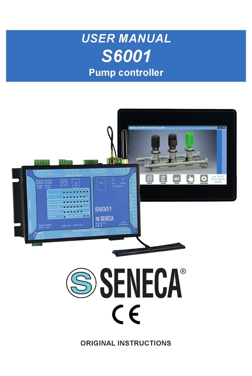
Seneca S6001 User manual

MI00415-1-EN INSTALLATION MANUAL 1/6
DOCUMENTATION
S6001-RTU-4GWW
DOCUMENTATION
S6001-RTU-E-4GWW
DOCUMENTATION
S6001-PC-4GWW
S6001 RTU
S6001 PUMP CONTROLLER
MODELS:
S6001-RTU4GWW ; 66001-RTU-E-4GWW ; S6001-PC-4GWW
INSTALLATION MANUAL
SENECA s.r.l.; Via Austria, 26 – 35127 – PADOVA – ITALY; Tel. +39.049.8705359 - Fax +39.049.8706287
WARNING: The full content of this manual must be read before any operation. The module must only be used by
qualied electricians. Specic documentation is available via QR-CODE shown on page 1.
Electrical and electronic waste disposal (applicable in the European Union and other countries with recycling).
The symbol on the product or its packaging shows the product must be surrendered to a collection centre
authorized to recycle electrical and electronic waste.
The module must be repaired and damaged parts replaced by the Manufacturer. The product is sensitive to
electrostatic discharges. Take appropriate measures during any operation.
PRELIMINARY WARNINGS
The word WARNING preceded by the symbol indicates conditions or actions that put the user's safety at risk.
The word ATTENTION preceded by the symbol indicates conditions or actions that might damage the
instrument or the connected equipment. The warranty shall become null and void in the event of improper use or
tampering with the module or devices supplied by the manufacturer as necessary for its correct operation, and if
the instructions contained in this manual are not followed.
CONTACT INFORMATION
This document is the property of SENECA srl. Copies and reproduction are prohibited unless authorised.
The content of this document corresponds to the described products and technologies.
Stated data may be modied or supplemented for technical and/or sales purposes.

MI00415-1-EN INSTALLATION MANUAL 2/6
MODULE LAYOUT
LED STATUS LED meaning
DO
(from terminal 1 to 15)
On Output enabled
Off Output disabled
DI
(from terminal 1 to 8)
On Input activated
Off Input deactivated
Signal level LED 6 ON Maximum reception level
LED 1 ashing Minimum reception level
PWR On Device powered
RX
(port COM2 and COM4)
On RS485 connection check
Flashing Reception of data packet completed on RS485
TX
(port COM2 and COM4)
On RS485 connection check
Flashing Reception of data packet completed on RS485
L1 L2
(level control)
L1 OFF / L2 OFF Liquid below the minimum level
L1 ON / L2 OFF Liquid between the minimum and maximum levels
L1 ON / L2 ON Liquid above the maximum level
SIGNALS VIA LED ON FRONT PANEL
Weight: 720 g
CERTIFICATIONS
https://www.seneca.it/products/s6001/doc/CE_declaration
INSULATION
POWER SUPPLY Voltage: 24Vac/Vdc ± 15% @ 50/60Hz
Absorption: 10VA max
ENVIRONMENTAL
CONDITIONS
Operating temperature:
-10°C ÷ +65°C
Humidity: 10% ÷ 90% non condensing
Storage temperature: -40°C ÷ +85°C
Altitude: up to 2000 m above sea level
TECHNICAL SPECIFICATIONS
1500 Vac
3000 Vac
60 mm
190 mm
105 mm
COM1
COM2
COM4
ETH
POWER
SUPPLY
ANALOG
I/O OUTPUT
INPUT

MI00415-1-EN INSTALLATION MANUAL 3/6
ASSEMBLY 35mm DIN rail IEC EN60715 or panel
CPU AND MEMORIES
CPU: 32 bits, 400MHz;
CPU I/O: 8 bits, 24MHz
Flash: 1GB
RAM: 64MB
FeRAM: 8KB FeRAM, divided into two (4KB) partitions for redundancy
DIGITAL
INPUTS
Type: PNP: Number of channels: 15; Connections: Removable terminals from 1 to 18
Optical isolation: YES; Current ON: > 4mA: Current OFF: < 3mA
DIGITAL
OUTPUTS
Type: SPDT free contact relay; Number of channels: 8;
Maximum current: 3A; Maximum voltage: 250Vac; Minimum load: 0.5W; Isolation: 3kV
ANALOGUE
INPUTS
Number of channels: 4; All in 0 – 20mA current;
Resolution: 12 bit; Precision: ± 0.3% compared to full scale; Input impedance: 50Ω
ANALOGUE
OUTPUTS
Number of channels: 1 @ 0 – 10Vdc; 1 @ 0 – 20mA
Resolution: 12 bit; Precision: ± 0.3% compared to full scale
Output impedance: Voltage: ≥ 1 kΩ; Current: ≤ 500 Ω
LIQUID LEVEL
CONTROL
INPUTS
Type: Conductive level control;
Number of channels: 2
Sensitivity: Adjustable
COMMUNICATION
PORTS AND
MEMORIES
Ethernet: 10/100 Base Tx with RJ45 connector
RS485 #COM2: Isolated serial port from 110 to 115200 bit/s (terminals 57-58-59)
RS485 #COM4: Isolated serial port from 110 to 115200 bit/s (terminals 54-55-56)
RS232 #COM1: Serial port complete with DB9 male connector
USB#1 host: USB A maximum current 300 mA @ 5Vdc
SD card supported: MicroSD card, max. 32 GB
SIM card (optional with Modem): Mini SIM type @ 3V with pressure slot
4G / LTE
WORLD WIDE MODEM
LTE-FDD: B1/B2/B3/B4/B5/B7/B8/B12/B13/B18/ B19/B20/B25/B26/B28 LTE-TDD: B38/B39/
B40/B41/B66 - WCDMA: B1/B2/B4/B5/B6/B8/B19
GSM: B2/B3/B5/B
For further information, refer to the User Manual.
Certications: Deutsche Telekom (Europe) Verizon*/AT&T*/T-Mobile*/Sprint* (North America)
TRANSMISSION
POWER
Class 4 (33 dBm ±2 dB) for GSM850
Class 4 (33 dBm ±2 dB) for EGSM900
Class 1 (30 dBm ±2 dB) for DCS1800
Class 1 (30 dBm ±2 dB) for PCS1900
Class E2 (27 dBm ±3 dB) for GSM850 8-PSK
Class E2 (27 dBm ±3 dB) for EGSM900 8-PSK
Class E2 (26 dBm ±3 dB) for DCS1800 8-PSK
Class E2 (26 dBm ±3 dB) for PCS1900 8-PSK
Class 3 (24 dBm +1 / -3 dB) for WCDMA bands
Class 3 (23 dBm ±2 dB) for LTE-FDD bands
Class 3 (23 dBm ±2 dB) for LTE-TDD bands
The Ethernet port with RJ45 connector can be used to connect an HMI display such as the VISUAL4 Seneca display or a
DCS or SCADA device.
ETHERNET PORT

MI00415-1-EN INSTALLATION MANUAL 4/6
RS232 / RS485 SERIAL PORTS
RS232 SERIAL PORT:
RS485 SERIAL PORT (COM2 and COM4):
The entire RS232 serial port is available through the male DB9 connector on the left side of the S6001.
To connect the RS232 devices, the CS-DB9F-DB9F cable is supplied on request.
The signals of the RS232 port in the DB9 connector are listed in the following table:
S6001 provides two RS485 ports with removable terminals: COM2 and COM4.
For more information, see the User Manual.
Terminals 60 - 61 - 62 provide an optional
communication bus.
Pin Name / Description Type
1 DCD; Data carrier detect; In
2 RXD; Receive data; In
3TXD; Transmit data; Out
4 DTR; Data terminal ready; Out
5 SG; Signal Ground;
6 DSR; Data set ready; In
7 RTS; Request to send; Out
8CTS; Clear to send; In
9 RI; Ring indicator; In
COM4:
54
55
56
B
A
COM2:
57
58
59
B
A
ELECTRICAL CONNECTIONS
POWER SUPPLY ALARM OUTPUT
52
51
53
38
37
39 Terminals 37 and 38 can be used to connect,
for example, a 12 Vdc 50mA max acoustic
alarm.
Terminal 39 must remain unconnected.
Switch the module off before connecting inputs and outputs.
To meet the electromagnetic immunity requirements:
- use shielded signal cables;
- connect the shield to a preferential instrumentation earth system;
- separate shielded cables from other cables used for power installations (transformers, inverters, motors, etc...).
CAUTION

MI00415-1-EN INSTALLATION MANUAL 5/6
DIGITAL INPUTS
All PNP type inputs are optically isolated.
17 D.I.14
18 D.I.15
16 D.I.13
15 D.I.12
14 D.I.11
13 +13 Vdc
0
11 D.I. 9
12 D.I.1
10 D.I. 8
9 D.I. 7
8 D.I. 6
7 +13 Vdc
5 D.I. 4
6 D.I. 5
4 D.I. 3
3 D.I. 2
2 D.I. 1
1 +13 Vdc
INPUTS FOR LIQUID LEVEL CONTROL
Terminals 40, 41 and 42 allow analogue control of the liquid
level in a tank or a cistern.
The uid level control inputs are software congurable.
41
40
42
COM LEVEL
LEVEL 1
LEVEL 2
ANALOGUE INPUTS AND OUTPUTS
Terminals 43 to 46 allow the connection of active
sensors.
Terminal 49 is a power output for passive current
sensors.
A.I. (0-20mA)
A.I. (0-20mA)
A.I. (0-20mA)
A.I. (0-20mA)
A.O. (0-20mA)
A.O. (0-10Vdc)
49 (12 Vdc)
50 (GND-A)
48
47
46
45
44
43
V
+
mA
+
+
+
++

MI00415-1-EN INSTALLATION MANUAL 6/6
CONNECTION IDENTIFICATION
A RS 232c
B Ethernet
C Power supply
D, E Analogue inputs /analogue outputs
F, I, L Relay outputs
G USB #1 Host
M, N, O Digital inputs
P, Q RS485
R Optional bus
S MicroSD card slot
T SIM card slot
U Main antenna
V Mobile antenna
A
B
E
F
D
C
S6001
I
N
M
L
O
P
Q
R
S
T
U
V
S6001
ASSEMBLY REGULATIONS
ASSEMBLY ON DIN RAIL
PANEL INSTALLATION
It is possible to install on DIN EN 60715 rail.
For installation on a DIN rail, use the supplied data supports.
Installation in the lower part of the electrical panel is
recommended.
Drill 4 holes for the screws (diameter 5 mm max), with the
distances marked in the figure. Fix the device with suitable
fastening elements (screws or rivets).
Be careful not to drop the device during the fixing operations
to avoid damaging it.
Installation in the lower part of the electrical panel is
recommended.
180 mm
65 mm
Other manuals for S6001
1
This manual suits for next models
3
Table of contents
Other Seneca Controllers manuals
Popular Controllers manuals by other brands

SmartWireless
SmartWireless SL9600TW quick start

Honeywell
Honeywell T775 Series Application guide and cross reference

Go Power
Go Power GP-RVC-R quick start guide

Schwank
Schwank ThermoControl Plus M2 OPERATING AND INSTALLATION Manual

Koma Elektronik
Koma Elektronik KOMMANDER user manual

Super Hot
Super Hot BC-1 manual