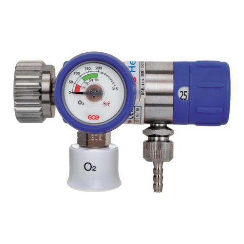
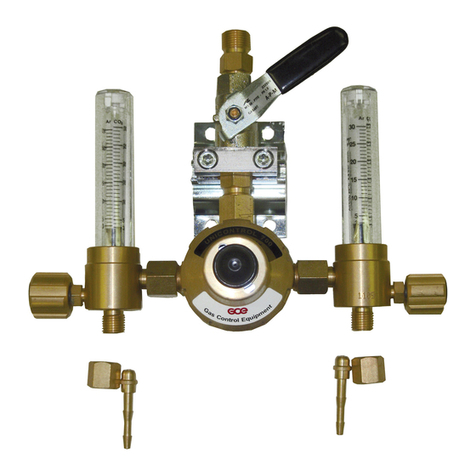
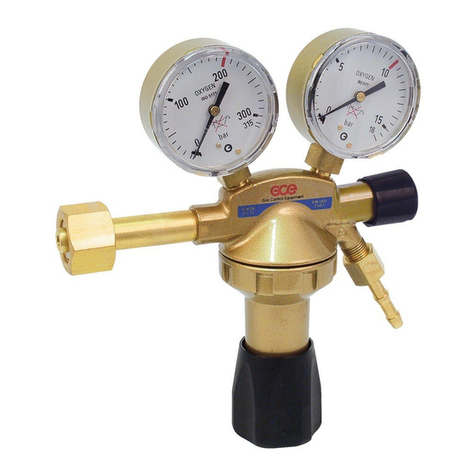
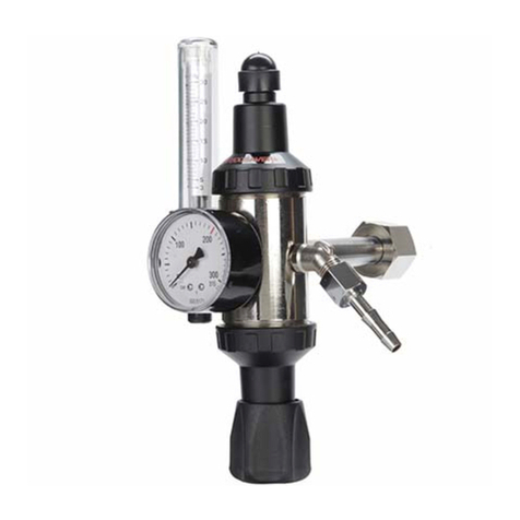
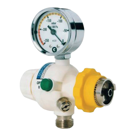
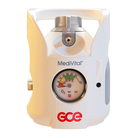
GCE mediline MEDIREG II User manual

Regulators IFU GB,FR,DE,NL Rev 03 Page 1/44 12/02/2010
MEDIREG
®
II, MEDISELECT
®
II
MEDICAL HIGH PRESSURE REGULATORS
Document Nr: 735 800 000 092
Date of issue: 12/02/2010
Revision Nr: 3
GB
FR
DE
NL

Regulators IFU GB,FR,DE,NL Rev 03 Page 2/44 12/02/2010
GCE Medical Regulators are medical devices classified as class IIb according to the
Medical Device Directive 93/42/EEC.
Their Compliance with essential requirements of 93/42/EEC Medical Device Directive is
based upon EN 10524-1 standard.
GCE Medical Regulators are designed for use with high-pressure medical gas cylinders
equipped with a medical cylinder valve. They regulate pressure and flow of medical
gases to the patient. They are intended for the administration of the following medical
gases in the treatment, management, diagnostic evaluation and care of the patient:
- oxygen;
- nitrous oxide;
- air for breathing;
- helium;
- carbon dioxide;
- xenon;
- specified mixtures of the gases listed.
- air or nitrogen to power surgical tools.
Operations
Transport
Storage
•Keep the product and its associated equipments away from
- heat sources (fire, cigarettes, …),
- flammable materials,
- oil or grease, (especially be carefull if hand cream is
used)
- water,
- dust.
•The product and its associated equipments must be prevented
from falling over.
•Always maintain oxygen cleanliness standards.
•Use only the product and its associated equipments in well
ventilated area.
Before initial use the product should be kept in its original packaging. GCE recommends
use of the original packaging (including internal sealing bag and caps) if the product is
withdraw from operation (for transport, storage).
Statutory laws, rules and regulations for medical gases, accident prevention and
environmental protection must be observed.

Regulators IFU GB,FR,DE,NL Rev 03 Page 3/44 12/02/2010
-20/+60 °C -30/+60 °C
10/100 % 10/100 %
600/1200 mbar 600/1200 mbar
•In case of storage at a temperature below -20 °C, d o not operate the regulator
until it has been allowed to increase its temperature to a minimum of -20 °C
•At regulators intended for use with mixture of medical gases O
2
+N
2
O is lower
operation temperature limit +5°C. During normal use the flow outlet and
pressure outlet will sometimes have a frosty appearance. This is a normal
physical reaction in the valve, due to that the gas is going from high pressure
to low pressure (Joule Thompson effect). Ensure that all equipment that is
connected to the valve by at least a 2 metre hose.
According to Medical Devices Directive 93/42/EEC the product owner must ensure that
all personnel handling the product are provided with the operating instructions &
performance data and are fully trained to carry out that operation. Trainees need to be
supervised by an experienced person.
The regulator acts as a pressure-reducer, gas from the cylinder valve passes through
the pressure regulator to the user outlets.
(Typical configuration of MediSelect II regulator)
(Configuration of MediReg II regulator with flowmeter)
A
B
D
F
E
B
C
F
A
E

Regulators IFU GB,FR,DE,NL Rev 03 Page 4/44 12/02/2010
!"
Regulator is fitted to the medical cylinder valve by mean of an inlet stem. The stem
can be bull nose type (male thread), nut type (female thread) or pin index type. The
inlet stem includes a filter.
#"
A cylinder contents pressure gauge is provided to indicate the cylinder contents (the
medical cylinder valve shut-off valve must be set to the ON position to allow the
pressure to register on the gauge).
$%&'"(
GCE regulators can be supplied with a flow-metering device - flow control head “C”
or flowmeter “D”. This function is used to supply a gas flow (l/min) at atmospheric
pressure directly to the patient through the flow outlet “E”, e.g. through a cannula or
a facemask.
The flow outlet “E” can be hose nipple (for cannula or mask) or outlet with thread (for
humidifier).
"
The regulator may be fitted with a pressure outlet. The pressure outlet is the outlet
directly from the low-pressure chamber. Two types of the pressure outlet can be
used:
Pressure outlet I - is fitted with a gas specific medical quick connector also called
“quick coupler” . The user can connect another piece of equipment to this outlet with
a gas specific male probe. The quick connector self seals when the male probe is
disconnected. This outlet is for supplying gas at a controlled pressure to power
medical devices, e.g. medical ventilator.
Pressure outlet II – is fitted with a threaded connector. The regulator with this type of
pressure outlet shall be only an integral part of a medical equipment (e.g.
emergency ventilators, anaesthesia devices, etc.)
•If the regulator is fitted with two pressure outlets, do not use both of them at
the same time. If you use both of them in the same time the performance of
the regulator will not be according to specification (see appendix 1) !!!
Note also that the product colour (especially flow control knob) might not be gas specific
colour coded.
)
)#
•Check if there is visible external damage to the product (including product labels and
marking) and on the gas cylinder. If it shows signs of external damages, remove it
from service and identify its status.

Regulators IFU GB,FR,DE,NL Rev 03 Page 5/44 12/02/2010
•Visually check if the product or the medical gas cylinder is contaminated; if needed,
for the regulator, use the cleaning procedure detailed in this section (if required for
the cylinder, refer to the gas cylinder manufacturer cleaning recommendation).
•Check if the product service is due or that the total life time of the product and the
gas cylinder has not been exceeded, (refer to GCE or owner’s date coding system).
If service or life time has been exceeded, remove the product (or the gas cylinder)
from service & suitably identify its status.
•Ensure that the product inlet stem is compatible with the medical cylinder valve (gas/
thread type).
•Check the presence & the integrity of inlet stem seals / correct size of seal.
•Remove caps from inlet and/or flow outlet. Keep caps in a safe place for reuse
during transport or storage.
•The product is dedicated only for use with the gas specified on its labelling. Never
try to use for another gas.
•Secure the gas cylinder stand.
Screw connection (bull nose or nut type)
•Manually screw the bull nose or the nut onto the cylinder valve connector.
•Turn the regulator into the correct position for use and tighten the nut by hand - do
not use tools.
Pin index connection
•Position the pin-index over the cylinder valve with the pin(s) on the pressure
regulator pointing towards the cylinder valve connector holes on the cylinder valve.
•Press the regulator inlet connection pins into the cylinder valve connector holes - do
not use force, otherwise the pins or holes may be damaged.
•Tighten the screw on the regulator onto the cylinder valve connector via the T-bar
handle. Do not use tools.
•Position the equipment so that the regulator user outlets point away from personnel
or patient.
•Fitting the regulator with too high a torque to the cylinder valve may result in
damage.
•During fitting to the cylinder valve, do not apply torque/load to any other parts
of the product.
•For regulators fitted with a flow-metering device, set the flow control knob on the
“ZERO” position - Ensure the flow control knob engages correctly.
•Open the cylinder valve slowly by turning the hand wheel in anticlockwise direction
approx 1 to 1½ turns.
•Sudden opening of the cylinder valve could result in a danger of fire or
explosion arising from oxygen pressure shocks. Insufficient opening of the
cylinder valve could reduce actual flow delivered.

Regulators IFU GB,FR,DE,NL Rev 03 Page 6/44 12/02/2010
•Visually check possible leakages:
- regulator inlet connection to cylinder valve
- pressure gauge to main body
- pressure relief valve vent hole(s)
- flowmeter (if any)
•Turn off the cylinder valve by turning the hand wheel in an clockwise direction to
stop position. Do not use excessive force.
•If any leakage is detected, use the procedure in chapter 6.3 and return the product
to GCE for service.
•Ensure the flow control knob is on the “ZERO” position.
•Ensure the cylinder valve is open – in the “ON” position.
•Check that the gauge indicates pressure/contents. If the pointer reaches the red
area send the cylinder for the filling
•For regulators fitted with a flowmetering device check that there is gas flow at each
setting (for instance, by listening for the sound of gas flow or checking presence of
bubbles in a humidifier).
•Turn off the shut off cylinder valve by turning the hand wheel in a clockwise direction
to the stop position. Do not use excessive force.
•Reset the flow control knob to on the “ZERO” position once the gas flow stops and
the regulator is vented..
•For regulators fitted with a pressure outlet, ensure it is functional by connecting and
disconnecting a male QC probe.
)*+,-
To be connected to the flow outlet:
Humidifiers, breathing masks or cannulas, gas savers, nebulizers.
To be connected to the pressure outlet:
Flexible hoses, flow meters, Venturi suction ejectors.
•At regulators fitted with pressure outlet together with ejector outlet don´t use
quick coupler and ejector outlet in the same time. Especially when inlet
pressure is bellow 50 bar it may negatively affect performance of the
regulator.
•Before connecting any accessory or medical device to the regulator, always
check that it is fully compatible with the product connection features & the
product performances.
Pressure outlet I
•Ensure the male quick coupler is compatible with the pressure outlet feature.
•Connect the male quick coupler.
•Check if the male quick coupler is fully engaged.
•Regulator with threaded connector as pressure outlet shall be only an integral
part of medical equipment. Do not use it for other purposes!

Regulators IFU GB,FR,DE,NL Rev 03 Page 7/44 12/02/2010
Pressure outlet II
•Ensure the counterpart is compatible with the pressure outlet features.
•Screw the counterpart.
•Check the counterpart is fully screwed.
•When is pressure outlet used by medical product with high flow consumption
(for example lung ventilator with request of source flow 100 l/min at minimal
pressure 2,8 bar) check the required capacity of source device with regulator
pressure outlet performance listed in appendix 1. To obtain enough
performance of the regulator is recomended replace cylinder when gauge
reach the red area.
•When connecting any accessory to the flow outlet make sure that it is not
connected to the patient before operating the product.
•Ensure the hose/humidifier is compatible with the flow outlet feature.
•Push the hose onto the regulator flow outlet/outlet for humidifier.
•Ensure the hose/humidifier is well engaged.
•Ensure that the flow control knob is on the ZERO position.
•Ensure that the accessory is connected to the flow outlet.
•Slowly open the cylinder valve by turning the hand wheel in anticlockwise direction
approx 1 to 1½ turns.
•Sudden opening of the cylinder valve could result in a danger of fire or
explosion arising from oxygen pressure shocks. Insufficient opening of the
cylinder valve could reduce actual flow delivered.
•Set the flow control knob on the required one of the available flow rates.
•Always ensure that the flow control knob has engaged and not placed
between two settings otherwise the flow selector will not deliver the correct
flow of medical gas.
•Do not try to apply an excessive torque on the flow control knob when it stops
on the maximum flow position or in zero position.
•The oxygen flow rate must be prescribed and administered by a clinically
trained user.
After completion of the therapy
•Turn off the cylinder valve by turning the hand wheel in a clockwise direction to stop
position. Do not use excessive force.
•Vent gas pressure from downstream equipment.
•Reset flow control knob on the ZERO position when gas venting has ceased.
•Disconnect the tube/humidifier from the flow outlet.

Regulators IFU GB,FR,DE,NL Rev 03 Page 8/44 12/02/2010
•Ensure that the flow control knob is on the ZERO position (if any).
•Ensure the accessory IS NOT connected to the pressure outlet.
•Slowly open the cylinder valve by turning the hand wheel in anticlockwise direction
approx 1 to 1½ turns.
•Sudden opening of the cylinder valve could result in a danger of fire or
explosion arising from oxygen pressure shocks. Insufficient opening of the
cylinder valve could reduce actual flow delivered.
•Connect the accessory to the pressure outlet.
After completion of the therapy
•Turn off the cylinder valve by turning the hand wheel in a clockwise direction to the
stop position. Do not use excessive force.
•Vent gas pressure from downstream equipment.
•
Disconnect the male QC probe from the pressure outlet.
)!
•Turn off the cylinder valve by turning the hand wheel in a clockwise direction to the
stop position. Do not use excessive force.
•Reset the flow control knob on the “ZERO” position – when the gas venting has ceased
(valid for version with flow-metering device only).
•Ensure the pressure gauge does not show any residual pressure.
•Remove connections from user outlets.
•Refit pressure outlet and flow outlet protection caps. Before refitting the caps, ensure
they are clean.
.$
Remove general contamination with a soft cloth damped in oil free oxygen compatible
soapy water & rinse with clean water.
Disinfection can be carried out with an alcohol-based solution (spray or wipes).
If other cleaning solutions are used, check that they are not abrasive and that they are
compatible the product materials (including labels) and gas.
•Do not use cleaning solutions containing ammonia!
•Do not immerse in water or any liquid.
•Do not expose to high temperature (such as autoclave).
/0
/(1
Form of nine digit serial number stamped on the product is following:
YY MM XXXXX
YY: year of production
MM: month of production

Regulators IFU GB,FR,DE,NL Rev 03 Page 9/44 12/02/2010
XXXXX : sequence number
Example: serial number 090300521 shows the regulator produced in March 2009, with
sequence number 521.
GCE recommend that a product Periodic inspection is undertaken every year to check
proper functionality of the regulator.
GCE recommend that after 5 years of operation an Overall maintenance function is
undertaken. This maintenance consists of preventive maintenance operations,
replacement of critical components and re-testing of the product. Overall maintenance
shall be carried out by GCE authorised person only.
.
It should not be assumed that the Periodic Inspection and Overall Maintenance period
recommended by GCE cover every safety procedure or practice required by local
regulations or statutory requirements, or that abnormal or unusual circumstances may
not warrant or suggest further requirements or additional procedures.
Maximum life time of the product is 10 years.
At the end of the product’s life time, the product must be withdrawn from service. The
owner shall put in place a relevant procedure to ensure the product cannot be used
again.
/2
!
Repairs activities cover the replacement of the following damaged or missing
components:
•Inlet stem,
•Flow-metering device,
•Gauge,
•Piston,
•Pressure relief valve,
•Quick coupler.
The repairs shall be carried out by a GCE authorised person only.
Any product sent back to a GCE authorised person for maintenance shall be properly
packaged. The purpose of the maintenance has to be clearly specified (repair, overall
maintenance). For product to be repaired a short description of fault and any reference
to a claim number might be helpful.
Some repair activities concerning to the replacement of the damaged or missing
components can be carried out by the owner of the product. The following parts can be
replaced only:
•Caps,
•Flow knob and stickers,
•Hose nipple (including o-ring),
•Inlet stem o-ring.
•Contact our customer service for appropriate component number
•All labels on the equipment must be kept in good, legible condition by the owner
and the user during the entire product life time.

Regulators IFU GB,FR,DE,NL Rev 03 Page 10/44 12/02/2010
•All seals and o-rings must be kept in dry, dark and clean environment by the owner
and the user during the entire product life time.
•Use only original GCE components!
34
Consult instruction for use Suitable for Home care use
Caution
Suitable for Hospital care use
Keep away from heat and flammable
material
Suitable for Emergency care
use
Keep away from oil and grease
Serial number
Upper and lower humidity limit Reference number
Upper and lower temperature limit
Batch number
Keep dry Fragile
Date of manufacture Manufacturer
Use by date Weight of product
Inlet parameter
Outlet parameter
P
1
Inlet pressure range P
2
Outlet pressure
P
4
Max outlet pressure (closing pressure) Q Outlet flow
Service or disposal date
The serial number indicates the year
the product has to undergo the overall
maintenance activities or has to be
disposed off. Refer to the serial number
note to determine the Overall
maintenance or disposal.
Ambient pressure limit
56
GCE guarantees the regulator for one year or in accordance with statutory warranty
rights, from date of delivery, against faulty design, material & workmanship.
GCE shall not be liable for loss of production, loss of profit or any other consequential
damage or indirect loss. In the event of any fault in the goods due to defective design,
materials or workmanship, our liability is limited to replacement of these goods, provided
that written notification is given to GCE within three months of the date of delivery or

Regulators IFU GB,FR,DE,NL Rev 03 Page 11/44 12/02/2010
deemed delivery, or such shorter time as may be specified in the quotation. Goods
returned to GCE will not be accepted unless GCE written consent to their return has
previously been obtained.
The liability of the regulator is irrevocably transferred to the owner or operator to the extent
that it is modified, serviced or repaired by personnel not employed or authorised by GCE or if
the apparatus is used in a manner not conforming to its intended use.
GCE cannot be held responsible for the misuse of the equipment in case of non-application
of the instructions for use.
APPENDIX :
Nr 1- Technical and performance data
Nr 2 - Quick coupling feature and connecting/disconnecting procedure
Manufactured by
GCE s.r.o.
Zizkova 381
583 81 Chotebor
Czech Republic
Tel : +420 569 661 111
Fax : +420 569 661 602
http://www.gcegroup.com
© GCE s.r.o.
This manual suits for next models
1
Table of contents
Other GCE Controllers manuals
