manuals.online logo
Brands
  1. Home
  2. •
  3. Brands
  4. •
  5. Midea
  6. •
  7. Controllers
  8. •
  9. Midea KJR-29B/BK-E User manual

Midea KJR-29B/BK-E User manual

R410A DC Inverter V4 Plus 50Hz MCAC-VTSM-2013-03
Control syste 185

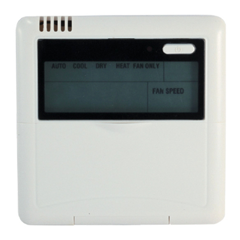
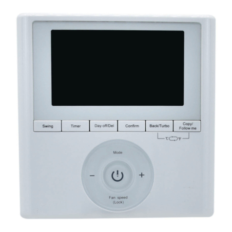
2.3 Touch- style key wired controller: KJR-29B/BK-E

KJR-29B/BK-E
Wired controller specifications
Model KJR-10B/DB(T)-E
Power Supply Voltage 5.0V DC
A bient Te perature Range -5°C~43°C
A bient Hu idity Range RH40%~RH90%
Perfor ance Features
1. Operating ode: Cool, heat, dry, fan and auto.
2. Set the ode through buttons.
3. Indoor setting te perature range: 17°C ~30°C.
4. LCD (Liquid Crystal Display).
5. Touch-style key
2.3.1 Function summarize
KJR-29B is the touch-style key wired controller.
New function Basic function
Air filter cleaning re inding function ON and OFF the air-conditioner
Indoor unit address setting function Auto-restart function
Re ote control receiver function Ti e ON and Ti e OFF setting
Lock the wired controller Clock setting
26 operation shortcut ℃setting and 26 operation lock℃
Setting the Operating ode, Te perature
Follow e Fan speed and Swing functions
MCAC-VTSM-2013-03 R410A DC Inverter V4 Plus 5
0Hz
186 Control Syste
2.3.2 Wired controller appearance
(1) Remote signal receiving function
There is the signal receiver for wireless re ote controller on the KJR-29B.You can use the wireless re ote
controller to control the air-conditioner through the wired re ote controller when the syste has been powered
on.
otes: The wired controller will not receive the swing controlling instruction. For the indoor unit with swinging function, you can
directly use the re ote controller to control swinging through the display panel of the indoor unit, or use the swing button on the
wired re ote controller to control the indoor unit for swinging.
(2) O /OFF Button
Press the ON/OFF button to control the indoor unit on and off status. When the unit is turned off, press the
ON/OFF button, the unit will be turned on and the operating icon lights up. When the unit is turned on, press
the ON/OFF button, the unit will be turned off and the operating icon lights off.
(3) Mode Button
Press the ode button to set the operating ode, after each button press the operation ode will circle as
follow:
When the controller has been set to cool-only, then there is no HEAT ode.
(4) Fan speed setting
Under COOL, HEAT and FAN odes, press the fan speed button can adjust the fan speed setting. After each
fan speed button press will circle as follow:
AUTO→LOW→MID→HIGH→AUTO
Under AUTO and DRY odes, the fan speed is not adjustable and the default fan speed is auto.
AUTO
COOL
DRY
HEAT
FAN
R410A DC Inverter V4 Plus 50Hz MCAC-VTSM-2013-03
Control syste 187
(5)Temperature setting
Under AUTO, COOL, DRY, HEAT odes, press the Te p adjust Up/Down buttons to set the te perature, the
adjusting range is 17℃~30 (℃or 62℉~88 ). The setting te perature cannot be adjusted under FAN ode.℉
(6)Timer on and Timer off setting
Press the ti er/clock setting button, then enter into the ti er on setting status, and the screen will display ti er
icon and .
You can press Te perature setting buttons to adjust the ti e. When the ti e setting is less than 10 hours,
each press the Te p setting buttons will increase or decrease 0.5 hour. When the ti er setting is ore than
10 hours, each press Te p setting buttons will increase or decrease 1 hour, the axi u ti er setting is 24
hours. After finish adjusting the ti e on setting, press the 26℃/OK button or wait for 5 seconds to confir and
exit the ti e on setting.
otes: If the wired re ote controller has been set ti er on/ off, press the ON/OFF button to turn on/ turn off the unit then the
ti er will be canceled si ultaneously.
(7) Clock setting
Long press the ti er/clock setting button for 3 seconds, and then enter into the clock setting status. The hour
position of the clock will flash, and can press Te p setting buttons to adjust the hour value.
After finish the hour setting, press left button or right button to switch to inute position setting, then the inute
position will flash, press Te p setting buttons to adjust the inute value. After finish the clock setting, press
the button or wait for 5seconds to confir and exit the setting state.
(8)26℃
℃℃
℃/OK button
Under AUTO, COOL, DRY, HEAT odes, press the 26℃/OK button can set the operating te perature to 26℃.
Long press this button for 3 seconds, the wired controller will lock the setting te perature to 26℃, and the
locking icon will be lighted up. Under the 26℃ operation locking state, the wired controller cannot adjust the
setting te perature through the te perature setting buttons, and also will not respond to the te perature
adjusting instruction fro the wireless re ote controller.
Long press 26℃/OK button for 3seconds, can unlock the 26℃operation locking state.
(9) Wired controller locking
Press the te perature adjusting UP and DOWN buttons si ultaneously, the wired controller enters into
locking state, and the locking icon will be lighted up. Under the locking state, the wired controller will not
respond to buttons by pressing and the control instruction fro the wireless re ote controller. Si ultaneously
press te perature adjusting buttons again can cancel the locking state.
(10) Air filter cleaning reminding function
The wired controller records the total running ti e of the indoor unit, when the accu ulated running ti e
reaches the pre-set value, air filter cleaning re inding icon will be lighted up, to re ind that the air filter of the
indoor unit needs to be cleaned. Long press left button for 3 seconds, and clear the re inding icon and the
wired controller will re-accu ulate the total running ti e of the indoor unit.
otes: The default setting value of re inding function is 2500 hours, and it can change to be 1250 hours, 5000 hours or 10000
hours. The setting ethods please refer to the installation anual.
(11)Swing Function
If the indoor unit supports swing function, press the right button to adjust the air outlet direction of the indoor
unit. Long press this button for 3 seconds can turn on or turn off the auto-swing function. When the auto-swing
MCAC-VTSM-2013-03 R410A DC Inverter V4 Plus 5
0Hz
188 Control Syste
function is turned on, the swing icon will be lighted up.
(12)Follow me function
When the syste is running and the operating ode is AUTO. COOL or HEAT, press the left button will
activate the Follow Me function. Press left button again will cancel follow e function. When the operating
ode is changed, and then will cancel this function as well. When the Follow Me function is activated, the icon
will be light up, and the wired controller will display roo te perature read fro the local sensor, and trans it
the te perature value to the indoor unit every 3 inutes.
(13) Setting addresses
Press the Te p. UP and DOWN button si ultaneously for ore than 8 seconds, then the controller gets
into address setting ode.
In the address setting ode, there are 2 ain functions:
Querying address: Press MODE button, the corresponding indoor unit will display its address.
Setting address: Use the UP and DOWN buttons to choose an address you want. Then press the FAN
button to set the indoor unit's address. The corresponding indoor unit will display the new address and
record it. After about 4 seconds, this displaying will fade out and indoor units turn to nor al display ode.
After setting addresses, users can press the 26℃/OK button can exit the address setting ode.
After each setting address and enter the query / set ode again, it will display the last set of address, but if
re-power, this address will be cleared.
In the address setting ode, wired controller does not respond to any co and fro re ote controller.
2.3.3 Installations
※ Preparation before Installation:
Make sure the following pasts has been prepared.
NO.
Na e QTY. Re arks
1 Wired Controller 1 /
2 Cross round heat wood
Mounting Screw 3 M4×20(For ounting on the wall)
3 Cross round heat
ounting Screw 2 M4×25(For Mounting on the electrical switch box)
4 Installation Manual 1 /
5 Owner's Manual 1 /
6 Plastic expansion pipe 3 For Mounting on the Wall
7 Plastic screw bar 1 For fixing on the 86 electrician box
8 Switching wires for
signal receiving board 1 For connecting the signal receiving board
and 4-core shielding wire
9 Switching wires for wired
controller signal 1 (If needed) For connecting the ain control
panel and 4-core shielding wire
R410A DC Inverter V4 Plus 50Hz MCAC-VTSM-2013-03
Control syste 189
※ Prepare for the following at installation site.
NO.
Na e Qty.(e bedded
into wall)
Specification re arks
(only for reference) Re arks
1 4-core Shield Cable 1 RVVP-0.5 2×4 0.05
2
×5 cable
no ore than 12M
2 86 electrician box 1 / /
3
Wiring Tube (Insulating
Sleeve and Tightening
Screw)
1 / /
※ Dimensions: 120*120*20mm
※ Wiring principle sketch:
Figure A
C
D
A
B
C
D
A
B
+5V
GND
+5V
GND
IR+
IR-
Wired Controller
4-Core Shield Cable, the length is decided by installation
Infraed Pipe
Indoor Unit
Indoor Unit Switch Board
MCAC-VTSM-2013-03 R410A DC Inverter V4 Plus 5
0Hz
190 Control Syste
※ Wiring figure:
1) Connect two ter inals of e bedded 4-core shielding wire with the switching wires of wired re ote controller
and signal receiving board. Make sure the sequence of 4 ter inals (A/B/C/D) should correspond to the wire
sequence of signal switching wires (A/B/C/D).
2) If e bedded 4-core shielding wire cannot go through the wired controller, it can use signal switching for
connection and ake sure the wires are reliable and fir . The tightening torque range of the screw
is0.8~1.2N . (8~12 kgf . c ).
※ Back cover installation
1) Use straight head screwdriver to insert into the buckling position in the botto of a wired controller, and spin
the screwdriver to take down the back cover. (Pay attention to spinning direction, if not you aybe da age the
back cover.)
C
D
A
B
C
D
A
B
CD
AB
+5V
GND
IR+
IR-
4-core shielding wire e bedded in the wall
Attached connecting wires for the signal receiving panel
Signal receiving panel
Front cover
Control panel
Screw
Signal switching wire
4-core shielding wire
e bedded in the wall
Attached connecting wires for
the signal receiving panel
Buckling position
Back cover
Front cover
Straight head screwdriver
R410A DC Inverter V4 Plus 50Hz MCAC-VTSM-2013-03
Control syste 191
2) Use three GB950-86 M4X20 screws to directly install the back cover on the wall.
3) Use two M4X25 GB823-88screws to install the back cover on the 86 electrician box, and use one GB950-86
M4X20 screw for fixing the wall.
4) Adjust the length of two plastic screw bars in the accessory to be the standard length fro the electrical box
screw bar to the wall. Make sure when install the screw bar to the electrical box screw bar, ake it as flat as
the wall.
otes: 1.Use cross head screws to fix the wired controller botto cover in the electric control box through the screw bar. Make
sure the wired controller botto cover is on the sa e level after installation, and then install the wired controller back to the
botto cover.
2. Over fasten the screw will lead to defor ation of the back cover.
Screw hole installed on
the wall,use three
GB950-86 M4X20
Screw hole fixed on
the wall,use one
GB950-86 M4X20
Screw hole installed
on 86 Electrician box,
use two M4X25
GB823-88
86 Electrician box
Signal switching wires
Back cover
MCAC-VTSM-2013-03 R410A DC Inverter V4 Plus 5
0Hz
192 Control Syste
※ Wiring
1) Wiring, three outlet positions
2) Shielded wiring
※ Front cover installation
1) After adjusting the front cover and then buckle the front cover; avoid cla ping the co unication switching
wire during installation.
2) Correct install the back cover and fir ly buckle the front cover and back cover, if not you aybe ake the
front cover drop off.
Upper left wire outlet
T
op side
wire outlet
Left iddle
side wire
outlet
Cutting place of top
side wire outlet
Cutting place of upper
left wire outlet
Cutting place of left
iddle side
wire outlet
Putty
Putty
Putty
Trap
Trap Trap
3) Avoid water enters into the wired controller, use
trap and putty to seal the connectors of wires during
wiring installation.
When under installation, reserve a certain length of
the connecting wire for convenient to take down the
wired controller while during aintenance.
R410A DC Inverter V4 Plus 50Hz MCAC-VTSM-2013-03
Control syste 193
※ Wired controller initial parameters setting:
1. Change the related functions of the controller through adjusting the initial para eters, details refer to table 1
2. The wired controller initial para eter includes two codes "XY", the first code "X" eans function class, and
the second code "Y" eans the detailed configuration of this function.
3. Setting ethod:
1)Si ultaneously press "Mode" and "Fan" button of the wired controller for 5 seconds to enter the para eter
setting state;
2) The value of this first code "X" is "0"; press the te perature setting button UP and DOWN to adjust the
second code value;
3) After setting the second code value, press 26/OK button to switch the first code to the next value;
4) When the first code value is "6", press 26/OK button again to exit the para eters setting.
4. The para eters setting function only under the situation which needs to adjust the default functions' setting
states; otherwise there is no need to do the setting.
Table 1
First code
Functions Second code
0 1 2 3 4
0 Cool-only/ Cool-Heat
selection
Cool-Heat
(Default) Cool-only / /
1
Indoor unit
co unication
address setting
Yes
(Default) None / / /
2 Auto-restart Yes
(Default) None / / /
3 Air filter cleaning
re inding function
Cancel the
re inding function
1250 hours 2500 hours
(Default) 5000hours
10000
hours
5 Re ote receiving
function
Yes
(Default) None
6 Centigrade/
Fahrenheit display Centigrade Fahrenheit / / /

Other Midea Controllers manuals

Midea KJR-12B/DP(T) User manual

Midea

Midea KJR-12B/DP(T) User manual

Midea KJR-120M(X4)/BGEF Installation instructions

Midea

Midea KJR-120M(X4)/BGEF Installation instructions

Midea CCM-270A/WS User manual

Midea

Midea CCM-270A/WS User manual

Midea CCM30/BKE-A User manual

Midea

Midea CCM30/BKE-A User manual

Midea KJR-29B/BKE-E User manual

Midea

Midea KJR-29B/BKE-E User manual

Midea KJR-120C/TF-E Operating instructions

Midea

Midea KJR-120C/TF-E Operating instructions

Midea KJR-120G1/TFBG-E Installation instructions

Midea

Midea KJR-120G1/TFBG-E Installation instructions

Midea KJRH-120H / BMKO-E User manual

Midea

Midea KJRH-120H / BMKO-E User manual

Midea KSACN0401AAA User manual

Midea

Midea KSACN0401AAA User manual

Popular Controllers manuals by other brands

RDZ 1057230 Technical sheet

RDZ

RDZ 1057230 Technical sheet

Graco 24G621 Instructions - parts

Graco

Graco 24G621 Instructions - parts

Uniden Bearcat BC-RH96 owner's manual

Uniden

Uniden Bearcat BC-RH96 owner's manual

Omron C200HS Series Replacement guide

Omron

Omron C200HS Series Replacement guide

BEIFANG VALVE ACTUATOR 920 Series instruction manual

BEIFANG VALVE ACTUATOR

BEIFANG VALVE ACTUATOR 920 Series instruction manual

Hach sc200 user manual

Hach

Hach sc200 user manual

Roger Technology H70/200AC Instruction and warnings for the installer

Roger Technology

Roger Technology H70/200AC Instruction and warnings for the installer

LG MultiSITE MS8000 Series user manual

LG

LG MultiSITE MS8000 Series user manual

Element Labs Versa Drive C1 user manual

Element Labs

Element Labs Versa Drive C1 user manual

Qorvo PAC5556 user guide

Qorvo

Qorvo PAC5556 user guide

Borg Warner Delco Remy 28MT Diagnostic Procedures Manual

Borg Warner

Borg Warner Delco Remy 28MT Diagnostic Procedures Manual

SE Controls TWIN SECO N 24 25 Technical information and operating instructions

SE Controls

SE Controls TWIN SECO N 24 25 Technical information and operating instructions

Mecc Alte DER1 instruction manual

Mecc Alte

Mecc Alte DER1 instruction manual

CADSBI motion SMART Operating and safety instructions

CADSBI

CADSBI motion SMART Operating and safety instructions

Mircom TX3 Series Installation quick reference

Mircom

Mircom TX3 Series Installation quick reference

Extron electronics MLC 62 Series Setup guide

Extron electronics

Extron electronics MLC 62 Series Setup guide

Omnia REGS12/08M manual

Omnia

Omnia REGS12/08M manual

Hober HBDC750 manual

Hober

Hober HBDC750 manual

manuals.online logo
manuals.online logoBrands
  • About & Mission
  • Contact us
  • Privacy Policy
  • Terms and Conditions

Copyright 2025 Manuals.Online. All Rights Reserved.