KONTRONIK BEAT User manual

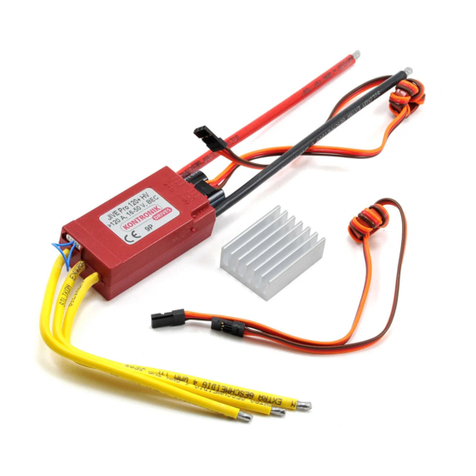
BEAT Speed Controller
Operation Manual

Technical data of the BEAT speed controllers
The BEAT speed Controllers are designed for brushless motors. They work without
sensors in the motor and have full part load capability. They are very sensitive and
have a soft and yet very fast start up. The built-in RPM control optimizes the app-
lication with helicopters and the mode programming helps essentially to program all
the various parameters. The Car Mode 2 allowed to drive back and forth.
BEAT controllers with BEC, 6-12 cells:
BEAT 40-6-12
40 A continuous current, 50 A for 15 sec
14 g / 33 g without / with cables - 52 x 26 x 7,5 mm
BEAT 70-6-12
70 A continuous current, 90 A for 15 sec
21g / 37 g without / with cables - 52 x 26 x 11 mm
BEAT – controllers with opto, 6-18 cells:
BEAT 40-6-18
40 A continuous current, 50 A for 15 sec
14 g / 33 g without / with cables - 52 x 26 x 7,5 mm
BEAT 55-6-18
55 A continuous current, 70 A for 15 sec
14 g / 33 g without / with cables - 52 x 26 x 7,5 mm
BEAT 80-6-18
80 A continuous current, 100 A for 15 sec
21g / 37 g without / with cables - 52 x 26 x 11 mm
BEAT FAI 7/10
150 A continuous current, 200 A for 15 sec
28g / 40 g without / with cables - 52 x 26 x 12 mm
BEAT – controllers with opto., 8-24 cells:
BEAT 40-8-24
40 A continuous current, 50 A for 15 sec
14 g / 33 g without / with cables - 52 x 26 x 7,5 mm
BEAT 60-8-24
60 A continuous current, 70 A for 15 sec
21g / 37 g without / with cables - 52 x 26 x 11 mm
BEAT FAI 24
150 A continuous current, 200 A for 15 sec
28g / 40 g without / with cables - 52 x 26 x 12 mm
BEAT – controllers with opto., 8-30 cells:
BEAT 30-8-30
30 A continuous current, 38 A for 15 sec
14 g / 33 g without / with cables - 52 x 26 x 7,5 mm
BEAT 50-8-30
50 A continuous current, 60 A for 15 sec
21g / 37 g without / with cables - 52 x 26 x 11 mm
BEAT FAI 27
100 A continuous current, 150 A for 15 sec
28g / 40 g without / with cables - 52 x 26 x 12 mm
Features of the BEAT speed controllers
The BEAT speed controllers utilize a operation mode programming for the users
convenience. In most cases it makes it unnecessary to program the individual
properties itself (as the EMF-brake or the undervoltage cut off ect.). If the properties
should be modified individually this is possible via the computer programming
software CPS PRO (order no. 9650).
sensorless, no sensor signals from the motor are required
mode programming
Auto-Programming-Mode (APM)
Glider-Mode
Motor-Plane- / Boot-Mode
Heli-Mode, active RPM control possible
Competition-Mode (F5B / F5B 10 cells / F5D)
Car-Mode 1: one direction, proportional brake
Car-Mode 2: back and forth
Reverse Motor Rotation
EMF-brake with variable brake rate, can be disabled
automatic undervoltage cut off at 0.8 V/cell, adjustable, can be disabled,
reducing power instead of cut off possible.
unlimited part load capability
analysis of switching off reason (shown by LED)
adjusting monitored by LED or audible signal
smooth start up
very sensitive control characteristic
selfadjusting beat frequence (8-32kHz), based on the sensing and computing of
the actual motor data
sensing of motor rotation direction
loose of one phase detection (connection off)
start up protection at power up, blocked motor protection, overtemperature
protection
over current limitation
100% surface mount technology (very small and light)
digital microprocessor control, therefore no thermal drift
highly flexible, heat-resistant cables
24 months warranty, fast repair service
CE tested, Made in Germany

Connection of the cables
Motor cables (red - green - blue)
The sequence is arbitrary. The motor rotation will be reversed by changing 2 motor
cables (see also mode programming Mode 7).
This speed controller needs no sensor information. If there is a sensor cable at the
motor, it will not be used.
Use only polarized connectors for the battery cables! Connecting the battery
with reverse polarity will destroy the speed controller. It contains a polarity sensor,
so incorrect polarity can easily be monitored.
Setting up the speed controller to your equipment:
The speed controller comes with an APM (Auto-Programming-Mode), so it will
adapt itself to the throttle positions of the RC.
Proceed as follows:
a) Switch on the Tx and Rx.
b) Set the throttle control to off.
c) Connect the battery to the BEAT speed controller.
d) Give 1 sec. full throttle or start with full throttle.
e) Ready.
If the motor fails to start, disconnect the battery and change over the throttle
servo reverse switch in the Tx. Start again from a) above.

Auto-Programming-Mode APM (Mode 1)
In APM the speed controller equalizes itself after every battery connection to the
actual throttle control. The brake rate is set to average (appx. 0.5 sec.), the
undervoltage cut off to 0.8 V/cell. Programming the APM deletes all previous
settings.
Programming sequence of Auto-Programming-Mode APM
Affix the jumper on any two of the 3 pins.
For an audible signal connect the motor to the BEAT.
Turn on the Tx and the Rx. Set the throttle
to EMF-brake position (back position).
Connect the battery.
Wait 2 sec. or until
Remove the jumper.
Set the throttle to full speed (front position).
Monitoring output
Ready - Disconnect the battery.

Glider-Mode (Mode 2)
All required properties for electric powered glider airplanes are preadjusted in this
mode.
The brake speed is set to average (app. 0.5 sec) and therefore suitable for direct
drive and many geared drives.
The undervoltage cut off is set to 0.8 V/cell and improves the battery endurance.
The overtemperature cut off and the overcurrent cut off is activated in order to
disconnect the motor at over load condition.
The throttle characteristic is optimized for the use of propellers.
The start parameters are optimized for large propellers running at low RPM.
The throttle positions are stored during the mode programming, so the
equalizing procedure is no more in use.
It’s possible to program a separate motor off position. In this throttle position the
motor is off and the EMF-brake is not activated. So a folding propeller keeps
open and can be used as an air brake.
If no separate motor off position is programmed, the motor off position is
identical to the brake position.
If flying with undervoltage disconnection and with out brake, change the trim
after programming so that the brake position is not reached in flight.

Programming sequence of Glider-Mode (Mode 2)
Affix the jumper on any two of the 3 pins.
For an audible signal connect the motor to the BEAT.
Turn on the Tx and the Rx. Set the throttle
to EMF-brake position (back position).
Connect the battery.
Wait 2 sec. or until
Remove the jumper.
...
Set the throttle to full speed (front position).
Now it’s possible to adjust a separate
motor off position (optional).
Monitoring output
Ready - Disconnect the battery.

The Motor-Plane-/ Boat-Mode (Mode 3)
All required properties for electric powered motor airplanes and boats are
preadjusted in this mode.
The EMF-brake is disabled.
The undervoltage cut off is disabled because the decreasing battery voltage can
easily be recognized. So the maneuverability will not be affected.
The overtemperature cut off and the over current limitation are activated to cut
off the motor at over load conditions.
The throttle characteristic is optimized for the use of propellers in boats and
planes.

Programming sequence of Motor-Plane- / Boat-Mode (Mode3)
Affix the jumper on any two of the 3 pins.
For an audible signal connect the motor to the BEAT.
Turn on the Tx and the Rx. Set the throttle
to motor off position (back position).
Connect the battery.
Wait 2 sec. or until
Remove the jumper.
... ...
Set the throttle to full speed (front position).
Monitoring output
Ready - Disconnect the battery.

The Heli-Mode (Mode 4)
In Heli-Mode the BEAT operates with active RPM control. This means, that the
motor RPM will be kept constant and changes of the load and the battery voltage
will be compensated. So it’s not necessary to use any mixer in the Tx to stabilize
the RPM. Just plug the receiver cable of the BEAT in a free slot of the Rx which can
be independently operated from the Tx with a slider. Program the BEAT to Heli-
Mode using this slider.
To start the motor push the slider towards full throttle. The BEAT will ramp up the
motor RPM in a few seconds in open mode. When the designated RPM is reached
the BEAT switches over to close loop speed. The more the slider position comes to
full throttle, the higher is the designated motor RPM.
With the slider back in motor-off position the motor will be switched off. Be aware
not to do so in flight, otherwise it would take several seconds to start the motor
again.
The range of RPM selected by the slider is self adjusted by the BEAT. When the
motor is started for the first time after the Heli-Mode has been programmed, the
BEAT is doing this adjustment. You must start the motor build in the helicopter, with
blades mounted. Otherwise RPM control will not work correct. So it may be
necessary to reprogram the BEAT to Heli-Mode when using an other cell count or
an other motor. Also if the BEAT is tested in HELI-Mode before it is used in the
helicopter, than it will be necessary to reprogram the BEAT to Heli-Mode again
before the first flight.
There is a check whether the battery, the motor, the gear ratio and the helicopter
are fitting well together: with the lowest possible RPM which can be selected after
the BEAT has adjusted it should not be possible to hover the helicopter. If it is
possible, the BEAT is operating out of it’s limit and can be destroyed! Use a higher
gear ratio or a motor with less RPM and more torque.
2 protection functions are still active in Heli-mode. If there is no Tx signal for a
longer time the motor is set to off. On overtemperature, the speed controller lowers
the power slowly (30 sec.) to zero. Restart is possible after disconnecting and
reconnecting the battery. (see also errors during flight)

Programming sequence of Heli-Mode (Mode 4)
Affix the jumper on any two of the 3 pins.
For an audible signal connect the motor to the BEAT.
Turn on the Tx and the Rx. Set the throttle
to motor off position (back position).
Connect the battery.
Wait 2 sec. or until
Remove the jumper.
... ... ...
Set the throttle to full speed (front position).
Monitoring output
Ready - Disconnect the battery

Competition-Mode (Mode 5)
All required properties for competition F5B airplanes are preadjusted in this mode.
The EMF-brake is set to maximum rate to fold the propeller immediately.
Caution: All components have to resist the resulting forces.
The undervoltage cut off and the overtemperature cut are disabled for
competition purpose.
Caution: Have enough cooling.
The start-up sequence is optimized to start the motor with large propellers as
quick as possible.
To prevent the speed controller from overload the time for partial load is limited.
If the speed controller is used in partial load too long it will switch off.
»For launch, the time period of partial load is limited to 6sec. If you want to
test before, a total running time of less the 2sec is free of charge. During
flight, a time of 1sec per running time is allowed. If the FAI Beat is used
longer in partial load it will be switched off.

Programming sequence of Competition-Mode (Mode 5)
Affix the jumper on any two of the 3 pins.
For an audible signal connect the motor to the BEAT.
Turn the Tx and the Rx on. Set the motor switch
to brake position (back position).
Connect the battery.
Wait 2 sec. Or until
Remove the jumper.
... ... ...
Set the motor switch to full speed (front position).
Monitoring output
Ready - Disconnect the battery.

Car-Mode 1: one direction, proportional brake (Mode 6)
All required properties for car models are preadjusted in this mode.
The EMF-brake is proportional. Therefore enough distance between the EMF-
brake position and the motor-off position of the throttle control is necessary.
The undervoltage cut off of 0.8V/cell is disabled.
The overtemperature cut off and the overcurrent limitation is activated to cut off
the motor at over load conditions.
The throttle characteristic is optimized for cars.
The response of the BEAT is as fast as possible to start driving as quick as
possible and to provide a direct drive feeling.
The throttle characteristic is optimized for cars.
Reverse Motor Rotation (Mode 7)
The motor rotation will be reversed by changing 2 motor cables or
programming mode 7. This mode does not change any other feature
programmed before. Wait during the programming on 7 signals, all others
like programming mode 3. Mode 7 only works if any mode except mode 1
has been programmed before.

Programming sequence of Car-Mode 1:
one direction, proportional brake (Mode 6)
Affix the jumper on any two of the 3 pins.
For an audible signal connect the motor to the BEAT.
Turn the Tx and the Rx. Set the throttle
to on motor-off position (middle position).
Connect the battery.
Wait 2 sec. or until
Remove the jumper.
... ... ...
Set the throttle to full speed (front position).
Now set the throttle to EMF-brake position
(back position)
Monitoring output
Ready - Disconnect the battery.

Car-Mode 2: back and forth direction (Mode 8)
All required properties for car models are preadjusted in this mode.
The speed controller is prepared to run back and forth
Runs the car in opposite direction as commended, it will be braked to stop and
then accelerated correctly.
The start parameters are optimized for cars.
The undervoltage cut off is disabled.
The overtemperature cut off and the overcurrent limitation are activated to cut off
the motor at over load conditions.
The throttle characteristic is optimized for cars.
The response of the BEAT is as fast as possible to start driving as quick as
possible and provide a direct drive feeling.

Programming sequence of Car-Mode 2:
both directions (Mode 8)
Affix the jumper on any two of the 3 pins.
For an audible signal connect the motor to the BEAT.
Turn the Tx and the Rx. Set the throttle
to on motor-off position (middle position).
Connect the battery.
Wait 2 sec. or until
Remove the jumper.
... ... ...
Set the throttle to full speed (front position).
Now set the throttle to EMF-brake position
(back position)
Monitoring output
Ready - Disconnect the battery.

Notes on safety
Never plug off the battery from the BEAT speed controller as long as the motor is
running.
In principle, do not attach the speed controller with cable ties, or similar things.
Electronic parts may be damaged.
As soon as a battery and a motor are connected to the speed controller, the
possibility exist, that the motor starts (e.g. by operating error or through electric
defect). Use caution from now on!
A motor (especially with propeller) can cause considerable injuries. Also parts
flying away can cause considerable injuries.
The use of this speed controller is only permissible in situations in which damage
of objects and injuries to persons are excluded.
Under no circumstances use a damaged speed controller further on (e.g. through
mechanical or electric reason, through moisture, a.s.o.). Otherwise it can come
later to a sudden failure of the speed controller.
The speed controller is constructed only for use in environments in which no
discharge of static electricity occurs.
The speed controller may only be supplied by NiCd or NiMH batteries. A use of
power supply or lead batteries units is not permissible. Any contact to the AC
mains network is prohibited.
A prolongation of the battery or motor cables should not be done. Otherwise
compliance with legal rules is not guaranteed. Also a destruction of the speed
controller can happen.
In the case of current measurement, a tie meter has to be used since an inserted
meter can damage the speed controller.

Error while programming
No signal appears:
The Tx is not turned on.
The receiver battery is not connected.
The speed controller is not connected to the Rx or pocketed wrong.
The jumper was not affixed and/or not removed again.
Signals, then steady burning light or nothing:
The throttle position „back" (brake and/or motor off position) is too dense to
the throttle position „front" (full speed position).
The distance between the throttle position „back" (brake and/or motor off
position) and throttle position „front" (full speed position) is too large. This
error can only occur with a computer Tx.
Correction: Program throttle control to +/-100%, if necessary lower.
The speed controller is pocketed in a wrong receiver socket.
Large shift of the throttle positions to long pulses (one of the throttle positions
must have a pulse length less than 2 msec.). This mistake can only occur with
computer Tx.
Correction: Set no shift to the throttle control (offset) at the Tx.
Errors in use
Unexpected motor cut off: The LED shows the reason if not turned on the throttle
again after cut off
»LED is blinking one time - Under voltage disconnection of 0.8V/cell reached.
»LED is blinking two times (not in Heli-mode) - Over current disconnection
while too long to much current.
Correction: Smaller prop or less cell count.
»LED is blinking tree times - Over temperature.
Correction: Improve the cooling of the speed controller

»LED is blinking four times - No Tx pulses.
Correction: Install the Rx and the antenna with more distance from the
speed controller and motor.
»LED is blinking five times - Too long partial load in F5B modes.
»LED is blinking six times - Internal error.
Correction: disconnect the battery and start again.
»LED is blinking seven times (only in Heli-mode) - Over current disconnec-
tion.
Correction: Better cooling or other gear ratio.
If the disconnection can not reliable be stopped, the KONTRONIK service
should be contacted to avoid the damage of the speed controller.
Motor can not be started:
The speed controller only unlocks the motor after connection of the battery when
recognising the throttle position EMF-brake and/or motor-off position. If the speed
controller do not recognise these positions no
is produced and the motor remains off.
Correction:
Consider the position of the trim of the throttle control and adjust to motor-off
and/or brake position.
Program the speed controller to the current throttle positions.
Some Rx’s show thermal drift. In this case, it’s recommended to keep some
distance to the end of the throttle control positions while programming, in
order to have some reserve available in use.
If there is a blinking signal the speed controller has detected a damage during
start-up. Send to KONTRONIK with description of blink code.
This manual suits for next models
12
Other KONTRONIK Controllers manuals

KONTRONIK
KONTRONIK JIVE Pro 80+ HV Installation manual

KONTRONIK
KONTRONIK KOSMIK 170 HV-I User manual

KONTRONIK
KONTRONIK KOBY 40+ LV User manual

KONTRONIK
KONTRONIK ProgUNIT User manual

KONTRONIK
KONTRONIK KOSMIK 160 HV User manual

KONTRONIK
KONTRONIK KOSMIK 160 HV User manual

KONTRONIK
KONTRONIK KOLIBRI 90 HV-I User manual

KONTRONIK
KONTRONIK Smile Series User manual

KONTRONIK
KONTRONIK KOSMIK 160 HV User manual

KONTRONIK
KONTRONIK KOLIBRI 60 LV User manual