GCE proFIT User manual
STRaIGHT LInE PoRTaBLE CUTTInG MaCHInE GB
TRaGBaRE BREnnSCHnEIDMaSCHInE
FüR GERaDES BREnnSCHnEIDEn DE
Přenosný řezací stroj Pro Přímé řezání kyslíkem
machine d’oxycouPage droite Portable CZ
MaCCHIna Da TaGLIo PoRTaTILE PER TaGLIo DIRETTo aD
oSSIGEno FR
máquina Portátil de corte transversal con oxígeno máquina cortadora
Portátil Para corte recto a oxigénio IT
Portabel skärmaskin för rätlinjig skärning med oxy-fuel
Переносной режущий агрегат для Прямой резки кислородом
Przenośny Półautomat do Prostoliniowego cięcia tlenem
hordozható lángvágógéP oxigénnel történő közvetlen vágásra
INSTRUCTION FOR USE
BEdIENUNgSaNlEITUNg
Návod k použití
MOdE d’EMplOI
ES
PT
SE
RU
PL
HU

MaNUalE d´USO
INSTRUCCIONES dE USO
INSTRUçõES dE USO
BRUkSaNvISNINg
ИнструкцИя по эксплуатацИИ iNstrukcja obsługi HaSzNálaTI úTMUTaTó
Page 1/156


4/222
GB
1. DESCRIPTIon
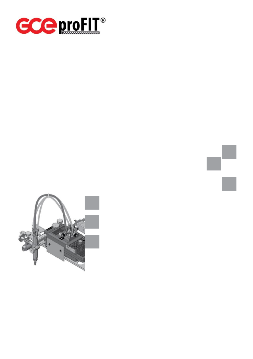
gCE proFIT®is portable oxy-fuel cutting machine
that cuts unalloyed steel by material combustion
with using of oxygen –fuel gas preheating flame.
This machine can also be used for linear and
circular cutting or for cutting curved (patterned)
profiles (figures) by moving manually or by
installing additional parts. there is an option to use
second cutting torch if necessary.
gCE proFIT®can be used for straight cutting,
curved cutting or bevel cutting with one or two
cutting torches at maximum. Maximal material
thickness to be cut is 150 mm with one cutting
torch and 100 mm with two cutting torches.
Complete machine consists of more parts to be
ordered separately, please see instructions and
recommendation below.
gCE proFIT® machine can also be used for plasma ®
Fig.1 Machine GCE proFIT with Zn-coated guide rail
cutting, preheating and welding but with additional equipment (not supplied with the machine) and by
making necessary changes. these operating instructions explain safe and efficient operation of gcE
proFit® .
GCE proFIT®portable cutting machine should be used taking the
warnings specified in the instructions into consideration.
operators of the machine shall have learnt the content of this Instruction for Use and shall be
experienced with oxy-fuel equipment and trained according to request of iso, en or national
standards with respecting all requests of legal authorities.
2. FEaTURES
2.1 TECHnICaL DaTa
Cutting capacity
Cutting speed
up to 150mm with one torch, up to 100mm with two torches
75 - 700mm/min
Operation
forward and reverse with variable speed
Circle cutting diameter
80 –1340 mm (optional up to 2340mm)
Max. strip width
485mm (cutting with two torches parallel)
power supply
Engine supply
230v aC / 50Hz
24v dC
Oxygen inlet connection
g1/4“, up to 8bar, hose min. dN8
Fuel gas inlet connection
g3/8“LH, up to 1bar, hose min. dN8

5/222
GB
Machine dimensions
180x380x160 (WxlxH) without torch, hoses and torch bar
Weight
13kg with one torch, 16kg with two torches
2.2 basic machine Package includes:
•equipment for one torch-cutting application
•one nozzle-mix cutting torch (only for 548900060001)
•torch holder, torch bar, stainless steel heat shield
•internal gas hoses, gas manifold with shut-off valves
•circle cutting pole, circle centre-piece
•10m electric cable with plug
•nozzle mounting and cleaning accessories
•flame lighter
•guide rail is delivered separately from the machine
2.3 ITEMS To BE oRDERED
Cutting machines and guiding rail-tracks
art number
Description
548900060001
gCE proFIT®machine with one nozzle mix torch, without track
548900060000
gCE proFIT®machine without torch, without track
304605904
Extension kit for second cutting torch
14088703
guide rail track 2 m, extruded aluminium profile with connecting clip
60010
guide rail track 2 m, zn/coated steel
cutting torches to be ordered with machine 548900060000, see also Fig.2:
Fig.2 Cutting torches

6/222
GB
art number
Description
Gas
type
Recomended cutting
nozzles
Pos.
0766262
Nozzle mix cutting torch
apMYF
aNME, aMd Collex,
pNME, k50pUz
1
0766221
BIR Mini, injector cutting torch
a
aC, (aSd)
2
0766222
BIR Mini, injector cutting torch
pMYF
pUz, (pSd)
2
0766173
FIT Mini, injector cutting torch
a
Ma133
3
0766174
FIT Mini, injector cutting torch
pMYF
Mp133, (MY133)
3

7/222
GB
2.4 MaCHInE CUTTInG RanGE
adjustment
cutting torch vertical movement adjustment:
75mm. distance of cutting torch center from the
edge of body:
•from 40 mm to 170 mm, with one cutting torch
•from 40 mm to 345 mm, with extension kit for
two cutting torches
circle cutting pole adjustment:
•from 40 mm to 670 mm, with one cutting torch
•from 40 mm to 840 mm, with extension for two
cutting torches
distance between cutting torches in case of
extension is used:
•60 mm, with two cutting torches next to each
other at the same side
•485 mm, with two cutting torches opposite to
each other
circle cutting dimensions:
•Ø80 mm –Ø1340 mm, with one cutting torch
•Ø80 mm –Ø1680 mm, with extension for two cutting torches
by adding a circle pole extension piece and second circle pole:
•For one cutting torch: from 40 mm to1170 mm (Ø 80 –Ø 2340 mm)
•For two cutting torches: from 40 mm to 1340 mm (Ø 80 –Ø 2680 mm)
2.5 CUTTInG noZZLES
Fig.3: GCE proFIT
®
with one cutting torch
Fig.4: GCE proFIT
®
with two cutting torches

8/222
GB
14001010
14001011
14001012
14001013
14001014
14001015
14001020
14001021
14001350
14001351
14001352
14001353
14001354
14001355
14001147
14001148
3-10
10-25
25-40
40-60
60-100
100-200
3-100
100-300
3-10
10-25
25-40
40-60
60-10
100-200
3-10
100-300
600-730
410-620
340-410
310-340
250-320
210-270
** H. n.
** H. n.
550-600
400-560
350-400
310-340
260-310
180-260
** H. n.
** H. n.
2,0-3,0
4,5-5,0
4,0-5,0
4,0-5,0
5,0-6,0
6,5-7,5
2,0-3,0
4,5-5,0
4,0-5,0
4,5-5,5
5,0-6,0
5,5-6,5
2
2,5
2,5
2,5
3
3,5
2
2,5
2,5
2,5
2,5
3,0-5,0
0,5
0,5
0,5
0,5
0,5
0,5
0,2
0,2
0,2
0,2
0,2
0,3
1,3-1,7
2,3-2,8
2,3-2,8
4,1-5,1
8,1-9,5
12,0-13,0
1,3-1,7
2,8-3,4
2,8-3,4
4,6-5,6
8,1-9,5
12,6-14,4
0,4
0,5
0,5
0,5
0,5
0,6
1,3
1,5
1,5
1,5
1,5
1,7-2,5
0,3
0,35
0,35
0,35
0,4
0,5
0,33
0,38
0,3
0,38
0,38
0,50-0,7
a
a
a
a
a
a
a
a
B
B
B
B
B
B
B
B
* cutting and heating nozzles are delivered separately, cutting nozzles in the 5 pcs package.
** H. n. = Heating nozzle
Pic. A: Injector nozzles
AC*
Fuel gas: A
Use with torch: BIR Mini
A, 0766221
Pic B: Injector nozzles
PUZ*
Fuel gas: PM
Use with torch: BIR Mini
PMYF, 0766222
Pic. C: Injector nozzles
MA133
Fuel gas: A
Use with torch: FIT Mini A,
0766173
Pic. D: Injector nozzles
MP133
Fuel gas: PM
Use with torch: FIT Mini
PMYF, 0766174
Pic. E Mixing nozzles
A-MD Coolex
Fuel gas: A
Use with torch:
Nozzle mix,
60009
Pic. F: Mixing nozzles K50
PUZ and K70 PUZ
Fuel gas: PMYF
Use with torch: Nozzle
mix, 60009
Pic. G: Mixing nozzles
ANME
Fuel gas: A
Use with torch: Nozzle mix,
60009
Pic. H: Mixing nozzles
PNME
Fuel gas: PMYF
Use with torch: Nozzle
mix, 60009

9/222
GB
202150330
202150331
202150332
202150333
202150334
202150335
202150336
202150320
202150321
202150322
202150323
202150324
202150325
202150326
14001450
14001451
14001452
14001453
14001454
14001455
14001456
14001749
14001750
14001751
14001753
14001755
14001761
3-8
8-15
15-30
30-50
50-70
70-100
100-200
3-10
10-15
15-30
30-50
50-70
70-10
100-200
3-5
6-10
10-25
25-40
40-60
60-100
100-150
3-10
10-25
25-40
40-60
60-100
100-200
650-900
600-800
460-680
360-575
340-475
250-365
150-250
600-750
540-635
440-610
380-510
320-460
280-400
150-250
750-800
700-750
500-650
420-500
360-420
270-360
210-270
550-660
400-560
340-400
300-340
260-310
180-260
3-5 5-
6
6-7
6,5-7,5
7,5
7-8
5,5-7,5
4-5 5-
6
6-7
6,5-7,5
7-7,5
7-8
5,5-7,5
2-3
4-5
6,5-7,5
6,5-8
6,5-8,5
6,5-8
6,5-7
2-3
3-4,5
4-5
4,5-5,5
5-6
5,5-6,5
1,5
1,5
1,5
1,5
2,3
2,3
2,0-2,5
0,1-0,8
0,1-0,8
0,1-0,8
0,1-0,8
0,1-0,8
0,1-0,8
0,1-3,8
1
1
1
1
1,5
1,5
1,5
2,5
3
3
3
3
3,5-5,5
0,2-0,8
0,2-0,8
0,2-0,8
0,2-0,8
0,2-0,8
0,2-0,8
0,6
0,1-0,8
0,1-0,8
0,1-0,8
0,1-0,8
0,1-0,8
0,1-0,8
0,1-0,8
0,3
0,3
0,3
0,3
0,3
0,3
0,4
0,3
0,3
0,3
0,3
0,3
0,4
0,25-1,85
2,15-2,6
3,6-4,15
5,2-5,85
7,8-8
11,1-12,3
11,7-15,7
2
2,32-2,6
3,6-4
4,85-5,7
7,4-7,75
11,1-12,3
11,7-15,7
0,4-0,55
1,2-1,4
3,2-3,7
4,6-5,5
5,6-7,1
9,1-11
12,2-12,9
1,3-1,7
1,7-2,6
2,8-3,4
4,6-5,6
8,1-9,5
12,6-14,4
0,55
0,55
0,55
0,55
0,715
0,715
0,75-0,85
2
2
1,6-1,75
2
2
2
2
1
1
1
1
1
1
1
1,4
1,6
1,6
1,6
1,6
1,8-2,6
0,5
0,5
0,5
0,5
0,65
0,65
0,58-0,77
0
0
0,40-0,44
0
1
1
1
0,5
0,5
0,5
0,5
0,7
0,7
0,7
0,36
0,41
0,41
0,41
0,41
0,49-0,7
C
C
C
C
C
C
C
d d
d d
d d
d
E
E
E
E
E
E
E
F
F
F
F
F
F
0768670
0768635
0768599
0768636
0768662
0769494
0769495
0769496
0769497
0769498
3 - 6
5 - 12
10 - 75
70 - 100
90/-150
3-6
5-12
10-75
70-100
90-150
1/32
3/64
1/16
5/64
3/32
1/32
3/64
1/16
5/64
3/32
470/-560
390/-480
205/-400
150/-220
125/-160
430/-150
360/-440
205/-380
150/-220
125/-160
2,5-3,5
2,0-4,0
3,5-4,5
4,5-5,5
5,5/-6,0
2,5/-3,5
3,0/-4,0
3,5/-4,5
4,5/-5,5
5,5/-6,5
0,3
0,3
0,3
0,5
0,5
0,2
0,2
0,2
0,4
0,4
1,25-1,65
2,12-3,2
3,2-4,45
8,4-9,8
9,2/-14,6
1,8/-2,98 3,3/-
4,95
5,0/-4,95
9,4/-12,8
14,0/18,6
0,3
0,4
0,45
0,6
0,75
0,3
0,4
0,45
0,6
0,75
g g
g g
g
H
H
H
H
H
10/222
GB
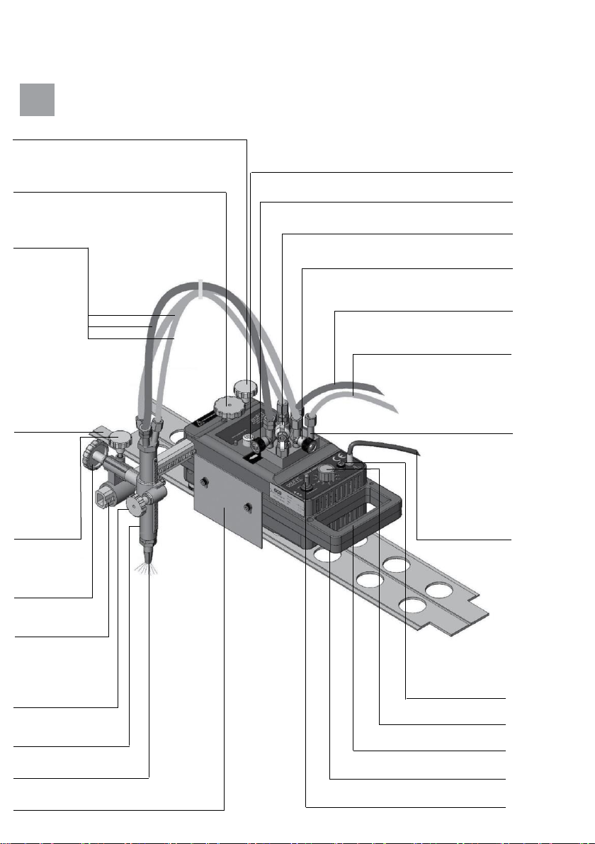
Fuel gas shut-off valve
Cutting oxygen shut-off valve
Heating oxygen shut-off valve
guiding
rail-track
Heat shield
Castor wheel for manual steering
Cutting nozzle
Cutting torch
with rack
Torch height
adjustment
hand-wheel
Forward-backward movement control
Machine body
Fuse (3a)
power cable
with plug (10m)
distance
adjustment bar
Cutting angle
hand-wheel
Torch
holder fixing
hand-wheel
Speed control
Internal gas
hoses
distance adjustment bar set up
handwheel
oxygen inlet connection: g1/4
Fuel gas inlet connection:
g3/8 lH
gas manifold
distance adjustment bar fixing hand-wheel

11/222
GB
Clutch lever
Fig.5: Machine description
3. MaCHInE InSTaLLaTIon
Machine is delivered partly dismounted with cutting torch and arm parts separated. take all parts out of the
pack. install them in sequence as below to operate it.
3.1. Power suPPly
check power supply before connecting the machine to the network (see above the point 2.1. technical data).
only undamaged plug and cable can be connected to the power network. only the way of connection
conforming to national standards shall be used.
description of the colours of the power cable single wires:
•brown: phase
•blue: Neutral
•green / Yellow: Earth
3.2. oxygen and fuel gas suPPly
3.2.1. inlet fuel gas hose should be with 8mm internal diameter at least (depends on the hose length). only
hoses according to iso3821 / EN559 shall be used. Machine hose in let connection is g3/8”LH with fitting
acc. to EN560. For fuel gas pressure and flow-rate follow please cutting nozzles chart with all details above.
3.2.2. Inlet oxygen hose should be with 6mm internal diameter (depends on the hose length and cutting
thickness). only hoses according to iso3821 / EN559 shall be used. Machine hose inlet connection is g1/4”
with fitting acc. to EN560. For oxygen pressure and flow-rate follow please cutting nozzles chart with all
details above (always the higher value should be taken from both heating and cutting oxygen).
note: in order to prevent flashback (flame backfire) hazards, appropriate flashback arrestors should be
used specified in accessories below. note: only undamaged gas hoses with undamaged, clean and properly
fastened fittings shall be used. Tightness of the hoses shall be tested every three months at latest with using
of maximal working pneumatic pressure in water bath. it is recommended to exchange all gas hoses every
three years at latest.
3.3. InSTaLL CaBLE anD InTERnaL GaS HoSES
together e.g. with using of hose brace.
3.4. install cutting torch bar, cutting torch holder and CUTTInG ToRCH
as shown at the pic. 5 to 8 in accordance with requested cutting shape.
3.5. ConnECT InTERnaL HoSES To CUTTInG ToRCH anD GaS ManIFoLD.
as the hose connection of each gas hose is different, it’s not possible to mix them together.
3.6. insert the Power Plug of your machine
to a proper socket (use the type of connection according to national standard). connect inlet oxygen hose
and inlet fuel gas hose to proper supply system. noTE: install your machine to an earthed plug in order to
avoid electrical power hazards.
4. oPERaTIon
4.1. BEFoRE STaRT CUTTInG
4.1.1. the operator shall be aware of safety operation specified in this instruction for use before any handling
with gCE proFIT®. the operator shall be experienced with oxy-fuel equipment and trained according to
request of iso, EN or national standards with respecting all requests of legal authorities.

12/222
GB
4.1.2. only the cutting nozzle according to chart above shall be used. Nozzle-mix/injector type of the cutting
torch has to be respected as well as type of the fuel gas. use only undamaged nozzle with undamaged and
clean seat.
4.1.3. please check also cutting torch head seat before mounting the nozzle into the cutting torch head. only
cutting torch from the list above with undamaged and clean nozzle seat can be used. Nozzle-mix/ injector
type of the cutting torch has to be respected as well as type of the fuel gas.
4.1.4. noZZLE CHooSInG please follow the chart with cutting nozzles above. use proper nozzle size
according to metal plate thickness. gcE cutting nozzles are designed for cuts of quality level 1 according to
EN iso 9013. it is possible to reach
maximal cutting speed by set-up cutting
parameters according to chart above,
cutting of straight cuts, by using of clean
metal sheet surface, quality cutting
machine, undamaged cutting nozzle and
oxygen with purity 99,5% or better. gas
pressures are measured at the torch
inlet.
4.1.5.tightening torque of the nozzles:
Nozzle-mix cutting torch: 22-30 Nm cutting
torch Fit Mini: 22-30 Nm cutting torch bir
Mini: 12 Nm for inner cutting nozzle and
18Nm for outer heating nozzle.
noTE: all parts in contact with oxygen should
be free of oil and grease due to explosion
hazards! check whether all threaded joints
and sealing surfaces, e. g. cones and balls,
are clean and undamaged!
4.2. FLaME IGnITIon anD SET UP
4.2.1. check all gas connection tightness.
4.2.2.adjust inlet gas pressures according to
the values in the table of cutting nozzles
above, see point 2.5. (1 bar = 1,05 kpa
100kpa = 105 N/m2, 1 bar = 14,22 psi). the
operating pressures for the heating oxygen
and fuel gas should be adjusted with open
torch valves. Open the fuel gas valve and
heating oxygen valve. ignite the outgoing
mixture with proper lighter supplied with the machine. With correct pressure adjustment is produced
carburizing flame. a neutral heating flame is to be adjusted with the fuel gas valve to suit the cutting task.
the heating oxygen valve remains fully open. Use a proper lighter given along with the machine to ignite the
flame. do not use hot metal or matchstick.
4.2.3. Open shortly the cutting oxygen valve to see correct adjustment of neutral flame and close it
afterwards (see also Fig.6).
4.3.CUTTInG PRoCESS InITIaTIon
Bring the torch to the initial cutting position and start locally heating the workpiece to the ignition
temperature, approximately bright red / yellow colour. then open the cutting oxygen valve and switch on
the feed in the same moment.
4.4. THE CoRRECT CUTTInG SPEED
can be seen from the slag production, from the Fig.7: Zn coated track extension almost vertical spray of sparks
and from the cutting noise. the approximate values of the cutting speed can be taken from relevant cutting
nozzle table as above.
Fig.6: Flame adjustment
Carburazing fl
ame
during ignitin
g
Neutral flame
Neutral flame wit
h
cutting oxygen jet
approx. 1 mm
Workpiece
Straight
edge
13/222
GB
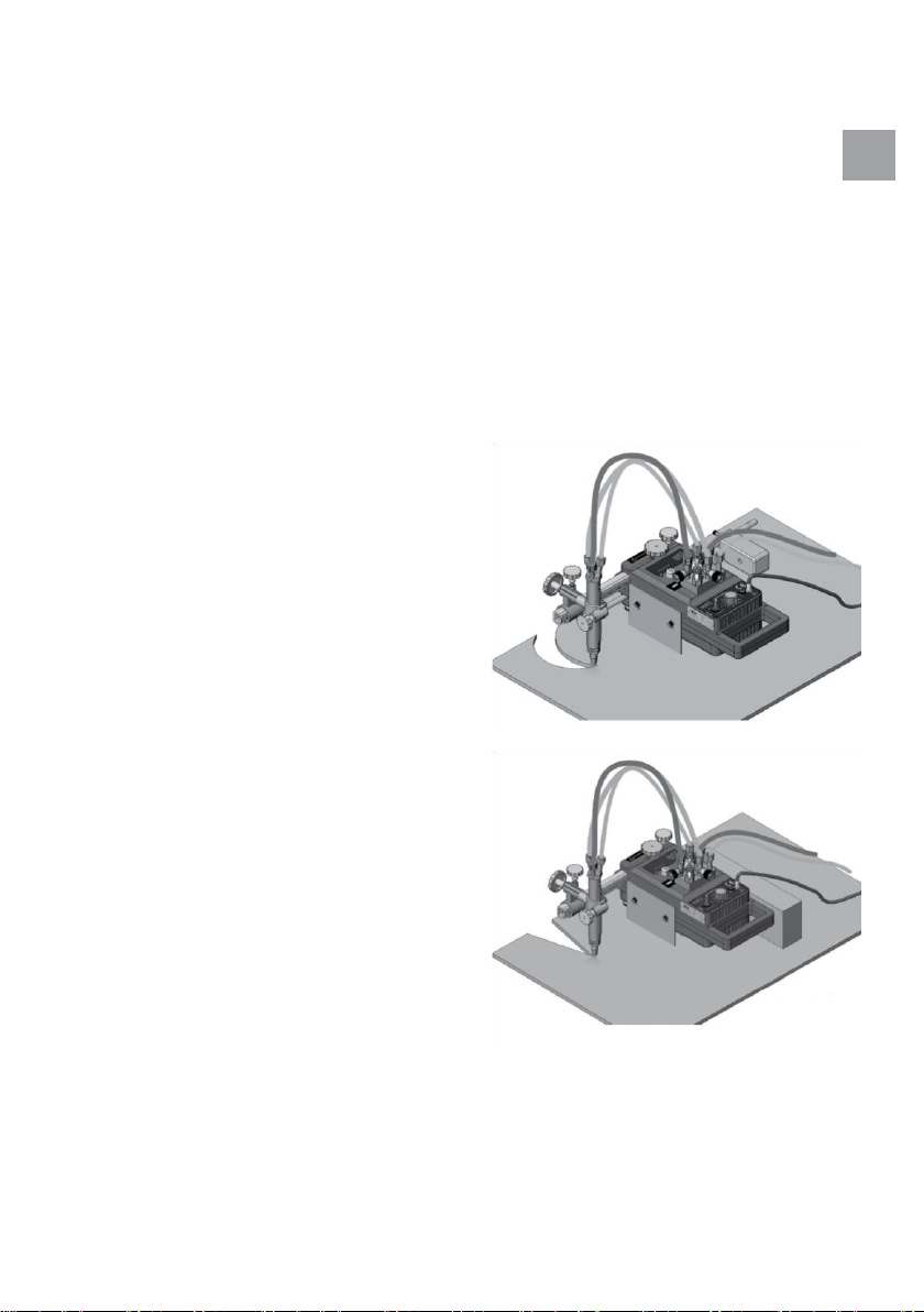
4.5. striPs cutting with guiding rail
4.5.1. place the rail on the part to be cut. if there is a need for a length more than 2m then connect the second
rail with the first as shown on Figure 7.
4.5.2. place gCE proFIT®on the rail. Make sure that front and rear wheels fit in the rail furrows.
rear wheel should fit,wthat it doesn’t move.
4.5.3. adjust the cutting speed in relation to particular nozzle and material thickness. adjust also movement
direction. turn clutch lever to the direction of arrow to stand-by position.
4.5.4. set the cutting torch on the metal sheet at the place of cut start. ignite and set pre- heating
flame as required according to instruction above. preheat the material on the ignition temperature.
4.5.5. Fully open cutting oxygen valve in the same time and start moving machine by switching of
movement control knob in requested direction as shown on the Figure 3 or 4.
4.5.6. after the cutting is over, stop the machine by bringing the movement control switch in central position,
shut all the gases of. gas valves shall be closed in following sequence: 1. cutting oxygen, 2. fuel gas,
3. heating oxygen.
4.6. striPs cutting with beam
(profile) guidance (see Figure 8)
4.6.1. use a metal profile which is 15 mm high at
least and fix it on the metal sheet according to
Figure 8.
4.6.2.Smooth edges of the metal beam should be
300 mm away from the edge to be cut.
4.6.3. Castor wheel should be slightly leant to the
template so that it moves to lean on the beam
when the machine moves backward.
4.6.4. continue according to points 4.5.3. –4.5.6.
4.7. CIRCLE anD RaDIUS CUTTInG
4.7.1. Install the components of circle pole and
centre piece as shown in Figure 9 for circular and
Fig.9: Circle cutting radius cutting. if circles with
small diameters are to be cut, then cutting torch
should be installed on the side of circle pole.
4.7.2. Make a punch sign on the center of the
circle to be cut which is 1.5 mm deep and 60
degree angle. disengage the revolving wheel and
place gCE proFIT®on the metal sheet.
4.7.3. It is recommended to drill 3 mm hole at the
place of cut start-end to ensure smooth cut
connection. it is possible to pierce also material
directly by oxygen which is usually recommended
for metal sheets with thickness below 80mm.
4.7.4. place the machine at the cut start point to
have cutting nozzle in exact position against the
drilled hole. start cutting according to points 4.5.3.
–4.5.6.
Fig.8: Cutting with beam guidance

14/222
GB
4.8. manually guided cutting
gCE proFIT®can be guided manually by the operator for free pattern cut over the outer line of the
pattern to be cut. castor wheel is to be adjusted
free for all directions and all of the three wheels
should be in contact with the panel. see also
Figure 10.
4.9. PREPaRInG oF THE METaL
sheet edges before welding
–bevel cutting with one torch (without weld root
face creation). prepare gCE proFIT® according to
point 4.5. above. Lose a bit the cutting angle
hand-wheel and turn the torch with the torch
holder to get requested angle. then tighten
properly again cutting angle hand-wheel. proceed
according to point 4.5. afterwards
4.10. cutting with two ToRCHES
In case the gCE proFIT®machine is equipped for
only one torch cutting operation, it is necessary to
mount Extension kit with second torch (part
number 304605904) first (see Fig. 11).
Please follow the steps:
1. dismount gas manifold for one torch from
the machine body and hoses from the
manifold.
2. Remove torch holder with torch from
distance adjustment bar and take the bar
from the machine.
3. Install second heat shield (6) at the
second side of the machine, opposite to
existing heat shield using distance
washer (7), imbus screw M6x20, washer
and spring washer (8, 9,10).
4. Mount gas manifold for two torches (1) on
the machine body.
5. put distance adjustment bar for two
torches into the machine.
6. Install both torch holders with cutting
torches at the distance adjustment bar.
7. Connect both torches and gas manifold Fig.11: Extension kit with second cutting torch with proper gas
hoses.
8. use proper cutting nozzles according to point 2.5 above. gcE proFit®machine with two
torches can be used for bevel cutting and for strip cutting as shown at the Figure 12.
Fig.10: Manually guided cutting

15/222
GB
Fig.12: Bevel cutting and strip cutting with two torches
noTE: in case when two torches are to be used too close to eachother, the required distance can be
adjusted this way that the first torch holder is directed to the front and the second one to the back of the
machine.
5. MaInTEnanCE
5.1. daily
•Continuously check the tightness of the nozzle-torch seat
•Wipe gCE proFIT®with a cloth to clean it from slag and metal oxides.
•check if there are damages in the hoses and electric cable. Exchange damaged parts.
•Lubricate the spindle of rotating wheel with shell “vitrea 31” or its equivalent.
5.2. monthly
•Make sure that vertical and horizontal torch movement is going well and all hand wheels are functional.
•clean torch rack, distance adjustment bar and all parts of the torch holder.
•check tightness the gas hoses and gas manifold incl. adjustment valves. tighten leaking connections and
replace the damaged parts.
5.3. quarterly
•dismount the clutch lever and screws and separate the upper part of the machine body from the lower part.
(make sure that motor cables are not stretched).
•clean the interior parts of the machine carefully without damaging the speed control unit.

16/222
GB
•
lubricate the engine connection parts, gears and clutch with a
molybdenum-disulphide based lubricant as a precaution.
•
reinstall body lids without compression any cables. connect
clutch lever.
•
Lubricate front and rear wheel bearings components.
•
Check if machine works properly and check gas tightness before
starting operating gCE proFIT
®
.
voltage changing
a proper transformer for 240v and 110v aC is installed within the
machine. the machine
is set for the voltage specified on the
identification label placed on the body of the machine. Following this
instruction to change the voltage of the machine:
•
dismount clutch lever and screws and separate upper part of the
machine body from
the lower part.
•
Change the position of electric cable from the switch panel as
shown in Figure 13.
•
Mount the upper and lower lids of the body together after closing
them.
•
Change the voltage marking on the
identification labels.
when separating the upper and lower parts of the body, make
sure that motor cables are not stretched.
note:
it is useful to mark on the identification shield the new voltage
value after changing . connecting machine to a wrong voltage can
lead to failures or caused dangerous conditions for the operator.
ELECTRICaL DIaGRaM
6.
Fig.13: Changing of the voltage
240V-110
V
110
v
v
240
7.
TRoUBLE SHooTInG
8.
v Control panel
240
110
v Control panel

17/222
GB
Failure
Cause
Repair
drive wheel
does not turn
Cable connections are loose
check the solder of the cables.
defective commutator
check the cable connection.
check the commutator with a test
device.
Failure of the main electric cable
Check the main electric cable with a
test device.
defective motor
check it with a test device. check if the
motor spindle rotates.
Ragged
Cutting
Surface
(see also
adjustment
recommendation
below)
a ragged surface
unfitting rail
Make sure that the surface to be cut is
smooth enough for the rail to fit
Rotating speed of the motor is
wrong
check or replace the control units.
External vibration
Stop vibrations
Wrong cutting parameters
adjustments
check the speed of cutting with the
ruler.
abnormal delays in propulsion
gear component
repair it or get it repaired.
distortion of the torch
replace it.
9. storage, carrying and transPortation
9.1. Packing
gCE proFIT®is surrounded by preservations all around
the box. cutting machine body is in the box separated
from the accessories; the box is divided into two parts.
9.2. SToRaGE
If the cutting machine is not going to be used for a long
time, keep the electric components, torch and nozzles
in the box to protect them from dust, humidity and other
impurities.
9.3. carrying
keep the product in the box to prevent failures arising
from shocks and vibrations during carrying.
9.4. TRanSPoRTaTIon
keep the product properly in its box to prevent it from
damages during transportation.storage, carrying and
transportation
Fig 14. An example of packing

18/222
GB
10. safety instruction
10.1. PRECaUTIonS oF oPERaTIon anD USInG
•Fix the machine position and install the machine properly before starting to use and check.
•Make sure that the switch is in “middle” position before inserting the plug into power socket.
•keep these operating and safety instructions with you when operating the machine.
•do not carry the machine while flame is on.
•prevent metal pieces or burr fall if the machine is working above the floor level.
•be very careful when transporting the machine to another place.
10.2. Protection Precautions regarding electricity system
•check the network voltage power before starting using. Maximal voltage variations should be ±10% of
the specified voltage. Machine shall not be used with different voltage.
use cutting machine only with the specified voltage.
•Earthen the cable of your machine.
•Send the machine to the authorized Service or the dealer you bought the machine from when following
situation happen:
•broken or worn cables.
•if water drips from your machine or if water leaks into the machine.
•if you see there is something wrong about operation in spite of proper operation.
•if the machine breaks down.
•complicated fault requiring repair.
•periodically check the electricity system.
10.3. MaInTEnanCE anD ConTRoL PRECaUTIonS
•assign a competent authorized person for maintenance and control.
•remove the plug from the socket before machine body opening and machine repair.
•apply periodical maintenance to the machine.
only use the proper cutting torch and nozzles. Respect the fuel gas type when choosing torch and
nozzle.
safety suits
•safety suits (gloves, protective glasses with proper light filter, helmet, and protetive shoes) shall be
used by operator during cutting operation.
•Wet clothes can lead to electricity accidents.
•keep the clothes free of oil and grease to avoid reaction with oxygen
11.

19/222
GB
12. Precautions which shall be taken in working aREa
•keep the flame away from the gas source, keep at least 3m safety distance (gas cylinders, pipeline, and
hoses)
•do not expose acetylene cylinder, pipeline, hoses and tubes to temperatures higher than 50°c (130°F).
•oxygen does not catch fire by itself, however in case of contact with another flammable material it easily
catches fire.
•Make sure that rate of oxygen within the working area is not higher than the rate in atmosphere.
•Flame forming as a result of contact of oxygen with lubricant, grease or other hydro-carbons lead to fire
and explosions. keep all components which can be in touch with oxygen free from oil and grease.
•oxygen, propane, propylene and their mixtures are heavier than air.
•ventilate the working room sufficiently during cutting.
•keep fire extinguisher, sand, water, etc. available in working area.
•keep flammable materials away from the location of cutting and from the sparks.
it is strongly recommended using of flashback arrestors for all gases. arrestors are to be mounted at the cutting
torch inlets. it is also recommended and according to local rules also mandatory to use flashback arrestors
mounted at the pressure regulator or pipeline outlet point.
flashback arrestors for machine cutting torches en 730-1
art number
Gas
Connection (En 560)
14008408
Cutting oxygen
g3/8”
14008263
Heating oxygen
g1/4”
14008278
Fuel gas
g3/8” LH
safety labels
Relevant labels are post on the machine for
proper using. Follow the instructions as necessary
and do not take out the labels while using the
machine. Make sure that the labels are always
clean and legible.
13.
flashback arrestors
14.

20/222
GB
adjustment recommendation for Perfect machine cutting
narrowing of kerf
(divergent)
•Forward speed of torch
too fast
•distance between nozzle
and sheet metal too big
•dirty and / or damaged
narrowing of kerf
(convergent)
•Forward speed of torch
too fast
•distance between nozzle
and sheet metal too big
•Cutting oxygen pressure
too high
Concave cut surface
beneath top edge
•Cutting oxygen pressure
too high
•dirty and / or damaged
nozzle
•distance between
nozzle and sheet metal
too big Step at bottom
edge
•Forward speed of torch
too fast
•dirty and / or damaged
nozzle
Melted down top edge
with adherent slag
•Cutting oxygen pressure
too high
•Heating flame too strong
•distance between nozzle
and sheet metal too big
Lower edge rounded
•Cutting oxygen pressure
too high
•Forward speed of torch
too fast
•dirty and / or damaged
nozzle
Excessive cut drag line
depth
•Forward speed of torch too
fast or irregular
•distance between nozzle
and sheet metal too small
•Heating flame too strong
Excessive cut drag line
depth
•Forward speed of torch too
fast or irregular
•distance between nozzle
and sheet metal too small
•Heating flame too strong
Single gouges
•Forward speed of torch
too slow
•Scaled or corroded or
dirty sheet metal surface •distance between nozzle
and sheet metal too small
•Flame too weak
•Flame extinguished with
a ban
concave cut surface profile
•Forward speed of torch too
fast
•dirty and/or damaged
nozzle or nozzle size too
small for the thickness to be
cut
•Cutting oxygen pressure too
low
irregular cut surface profile
•Cutting oxygen pressure too
low
•dirty and / or damaged
nozzle
•Forward speed of torch too
fast
Edge melting on
•Forward speed of torch too
slow
•Heating flame too strong
•distance between nozzle and
sheet metal too big to too
small
•Nozzle size too big for the
thickness to be cut
string of solidified droplets
• Heating flame too strong
•distance between nozzle
and sheet metal too small
•Scaled or corroded sheet
metal surface
nozzle
Table of contents
Languages:
Other GCE Cutter manuals

Popular Cutter manuals by other brands


Alpha Professional Tools
Alpha Professional Tools ESC-150 instruction manual

JMA
JMA VOLGA BIT user manual

ICS
ICS SpeedHook 814PRO Operator's manual

Mejix
Mejix CMER 200B Original manual translation

Mul-t-lock
Mul-t-lock KC5 User's operation manual

Gastrodomus
Gastrodomus TA25K Installation, use and maintenance


