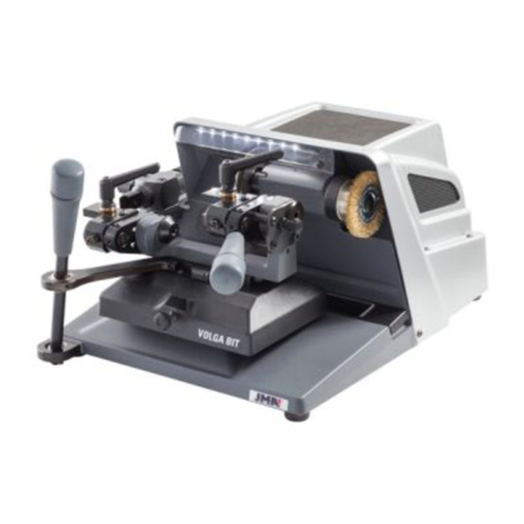
JMA VOLGA BIT User manual

VOLGA BIT
www.jma.es
MÁQUINA DUPLICADORA
MANUAL DE INSTRUCCIONES
KEY CUTTING MACHINE
MUSER MANUAL
SCHLÜSSELKOPIERFRÄSE
ANWEISUNGSHANDBUCH
MACHINE A REPRODUIRE
MANUEL D’INSTRUCTIONS
MÁQUINA DUPLICADORA
MANUAL DE INSTRUÇÕES
MASZYNA DO KOPIOWANIA
PODRĘCZNIK UŻYTKOWNIKA


ENGLISH
VOLGA-BIT
USER MANUAL
KEY CUTTING MACHINE

ENGLISH
1.- PRESENTATION AND GENERAL ASPECTS
1.1 GENERAL ASPECTS
1.2 TRANSPORTATION AND PACKAGING
1.3 IDENTIFICATION LABEL
2.- MACHINE CHARACTERISTICS
2.1 ACCESSORIES
2.2 ELECTRIC CIRCUIT
2.3 TECHNICAL DETAILS
2.4 MAIN ELEMENTS OF THE MACHINE
2.5 COMPONENTS AND FUNCTIONAL PARTS
2.5.1 Changing the cutter and tracer
2.5.2 Cutter speed
2.5.3 Locking the slide on the “X” axis
2.5.4 Tracer movement spring
2.5.5 Vertical adjustment of the tracer
3.- KEY CUTTING
3.1 KEY CUTTING PROCESS
3.2 KEY CUTTING
3.2.1 SEA-1 key
3.2.2 OP-WH.P and OP-WY.P keys
3.2.3 HU-HAA.P key
3.2.4 BM-6.P key
3.2.5 ME-4.P, ME-6.P, ME-7.P and ME-8.P keys
3.2.6 KA-2, KA-3 and KA-4 keys
3.2.7 WIN-1D, WIN-2D, WIN-3D and WIN-4D keys
3.2.8 JIS-4.P key
3.2.9 FO-6.P key
4.- MAINTENANCE
4.1 ADJUSTING THE CLAMP
4.2 REPLACING THE FUSES
4.3 TIGHTENING AND REPLACING THE BELT
4.4 REPLACING THE MOTOR
4.5 REPLACING THE CONNECTIONS PLATE
4.6 REPLACING THE LED LIGHTS
5.- SAFETY
6.- MACHINE WASTE
6.1 PACKAGING
6.2 SWARF
6.3 MACHINE
7.- ASSEMBLY DRAWING
8.- KEY-CUTTER-TRACER-ADAPTOR TABLE
11
11-12
12-13
13-14
14
14
42
43- 46

ENGLISH
13
1.- MACHINE OVERVIEW
1.1 GENERAL ASPECTS
The VOLGA-BIT cutting machine has been designed taking into account the safety
regulations in force in the EEC.
The safety of the personnel involved in the handling of this type of machine is
only achieved with a well-designed personal safety programme, such as the
implementation of a maintenance programme and follow-up to the recommended
advice, as well as compliance with safety regulations contained in this manual.
Although the installation of the machine presents no difficulty, it is preferable that you
do not attempt to install, adjust or handle it without reading this manual first.
The machine leaves our factory ready for use and only needs calibration operations for
the tools that are going to be used.
1.2 TRANSPORTATION AND PACKAGING
The VOLGA-BIT machine is presented in a sturdy cardboard box protected with
packaging foam, of the following dimensions:
Width = 570 mm; Depth = 570 mm; Height = 380 mm;
Weight (including packaging) = 28 Kg.
When unpacking the machine, carefully inspect it for any damage during transport.
If you find any anomaly, immediately notify the carrier and do nothing with the
machine until the carrier’s agent has carried out the corresponding inspection.
To move the machine from one place to another, we recommend that you only lift the
machine by its base and not by other parts.
1.3 IDENTIFYING LABEL
The VOLGA-BIT cutting machine comes with an identifying label, with specification of
the serial number or machine registration, name and address of the manufacturer, CE
mark and year of manufacture.
2 MACHINE FEATURES
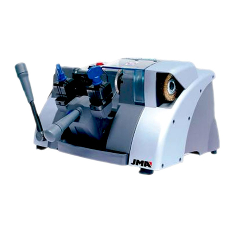
The VOLGA-BIT is a modern cutting machine for mortise-type keys and frontal keys.
2.1 ACCESSORIES
The machine is supplied with a series of accessories for its use and maintenance:
- 2 Counterpoints for female keys with narrow holes
- 2 Counterpoints for female keys with wide holes
- 2 Counterpoints for special male keys
- 2 Rods to make the adjustment (Ø5x70)
- 1 Rod for the change of cutter or brush (7x70)
- 1 Fixed key of 18
- 1 Set of Allen keys (2, 2.5, 3, 4, 5, 6)
2.2 ELECTRICAL CIRCUIT
The main components of the electrical and electronic circuit are the following:
1. Plug
2. Start switch (RED light)
3. Push button for brush (BLACK)
4. Motor
5. Transformer
6. LED lighting diodes
7. Connection plate
2.3 TECHNICAL DATA
Motor: Single phase 220V; 50Hz; 0,25Kw; 1,500 rpm (Optional: 110V; 60Hz; 0,25Kw;
1,500 rpm)
Cutter: FP19 HSS (Ø80x1.4x16)
Cutter speed: 750 rpm
Transmission: Ribbed belt.
Clamps: Self-centring
Movements: Guides with roller cages
Useful courses: X = 62 mm; Y = 47 mm
Lights: Led
Dimensions: Width = 370 mm; Depth = 460 mm; Height: 260 mm
Weight: 26 Kg
2.4 NOMENCLATURE OF THE KEY
1. Head
2. Stem
3. Bit
4. Teeth
2.5 MAIN ELEMENTS OF THE MACHINE
1.- Cutter
2.- Brush
3.- Clamp
4.- Clamp handle
5.- Carriage forward control
6.- Round point control
7.- Probe support
8.- Copier index
9.- Lighting
10.-Start-up switch
12
34
5
6
7
8
9
10
11
12
13
14
15
16
17 18
19
20
2.6 COMPONENTS AND FUNCTIONAL PARTS
2.6.1 CLAMP
The clamp is a fundamental part of the VOLGA-BIT machine. It has been studied to be
able to cut as many keys as possible, using counterpoints for the cutting of some of
them.
2.6.2 ROTATION LOCK OF THE RIGHT-HAND SIDE CLAMP
The clamp on the right side of the BIT carriage has the handle “16”, which allows the
locking and unlocking of the rotation.
Locking the rotation of this clamp is useful for:
• Copying frontal keys.
• Facilitating the fastening of the keys in the clamp.
• Facilitating the realization of the “bit stop against the cutter” (in the case of
short keys).
2.6.3 COUNTERPOINTS (USE MODE)
The VOLGA-BIT machine has three pairs of counterpoints, to facilitate the attachment
of different types of keys:
1
234
11.- Push button of the brush
12.- Adjustment control in depth of the probe
13.- Carriage fixing handle
14.- Carriage locking handle in the X direction
15.- Handle for the probe’s spring
16.- Grip lock handle of the clamp
17.- Tray for accessories
18.- Hole for locking the head
19.- Chip tray
20.- General power socket

ENGLISH
14
FINE POINT COUNTERPOINTS: for FEMALE keys with a small hole
Hole: from Ø3 to Ø4 Stem: greater than Ø5
THICK POINT COUNTERPOINT: for FEMALE keys with a large hole
Hole: from Ø4 to Ø5.5 Stem: greater than Ø6
TAPERED HOLE COUNTERPART: for MALE keys with plastic head, with square stem, ...
Stem: greater than Ø4
The correct way to use the counterpoints, is the following:
1) FASTEN THE KEY:
Fasten the keys, as follows:
FEMALE key: make a stop against the LATERAL STOP
MALE key: make a stop against the CUTTER-PROBE.
2) FIT THE COUNTERPOINTS:
Choose the pair of counterpoints, depending on the type of key.
NOTE: To help identify them, they have different engravings on the end of the head.
The counterpoint is inserted inside the carriage bushing, manually threading it. Stop
inserting it when you see it has reached as far as the key (DO NOT FORCE IT).
3) RELEASE THE KEYS:
Release the keys, before removing the counterpoints.
4) REMOVE THE COUNTERPOINTS:
Remove the counterpoints, turning them manually.
2.6.4 MAXIMUM LENGTH OF KEY
The VOLGA-BIT machine has been designed in such a way that there is no limitation
on the length of the key to be cut.
It has clamps at two heights, in such a way that the clamp on the left side does not
prevent the attachment of any key length.
2.6.5 PROBE SPRING
The VOLGA-BIT machine has the handle “15” that activates the probe’s spring.
The probe spring facilitates the insertion of the probe between the teeth of the key,
for the subsequent guidance of the key towards the cutter.
2.6.6 LOCKAGE OF THE X AXIS
The VOLGA-BIT machine has the handle “14” that locks-unlocks the movement of the
carriage in the X direction.
The locking function of the X axis is useful when we want the carriage to move
forward and without the possibility of lateral movements. It is also useful when we
want to cut keys with the optional clamp carriage for vertical cuts.
Locking the X axis also facilitates the operation of fastening-releasing the keys from
its clamps, by preventing the carriage from sliding to the sides.
2.6.7 Y AXIS LOCKING
The machine also has a slight lock at the end of the course of the Y axis, to prevent
the carriage from sliding forward during the operation of fastening-releasing the keys
from its clamps.
Just bring the carriage of the machine to its most extreme position towards the user,
so that we can see that the carriage is locked by means of a small spring.
To unlock the carriage, simply push the carriage lever forward slightly.
2.6.8 CLAMP CARRIAGE FOR VERTICAL CUTS (OPTIONAL)
The VOLGA-BIT machine has a special carriage (optional purchase), to make vertical
cuts of some models of keys. It is called clamp carriage for vertical cuts.
To swap the BIT carriage and the clamp carriage for vertical cuts, the machine has the
handle “13”, which locks-unlocks the carriage.
Before performing the carriage swap operation, it is very useful to lock the X and Y
axes of the machine.
The carriages are removed and inserted on the right side of the machine.
3 OPERATION AND FUNCTION
3.1 ADJUSTMENTS
The VOLGA-BIT cutting machine is adjusted from the factory. However, it is advisable
to make some adjustments after any of the following situations:
• After replacing a cutter, probe or clamp.
• After a long period of use.
3.1.1 SIDE ADJUSTMENT
• Lock the rotation of the clamp on the right side, operating the handle “16”.
• Tie a frontal virgin key, in the right-side clamp.
• Move the central area of the key towards the cutter.
• Lock the X axis of the carriage, operating the handle “14”.
• Execute a straight groove of approximately 8 mm. of depth.
16
• Release the key on the right-side clamp and fasten it on the left side clamp.
• Slightly loosen the two “L” screws that secure the probe support “7”.
• Move the probe support “7” to the left or right, until the probe is inserted into
the slot that we previously made in the key.
• In this position, fasten the probe support “7” by means of the two “L” screws.
• Now you can unlock the X axis of the carriage, operating the handle “14”
7
L
L

ENGLISH
15
3.1.2 CUTTING DEPTH ADJUSTMENT
• Lock the rotation of the clamp on the right side, operating the handle “16”.
• Fasten the adjustment rods in the clamp.
• Unlock the rotation of the handle “12”, loosening the screw “M”.
• Activate the probe spring, acting on handle “15”.
• Move the carriage forward, so that the adjustment rods rest on the “T” probe
and the “C” cutter.
• Operating the handle “12”, move the probe forward or backward, until the
probe “T” is resting on the adjusting rod “VT”, the “C” cutter lightly rubs the
adjustment rod “VC”.
• Re-tighten the “M” screw.
16
12
M
15
T
C
VT
VC
3.1.3 LATERAL STOP ADJUSTMENT
• The BIT carriage is supplied with the factory-set Lateral Stops, so it is NOT
necessary to adjust them again.
• However, after replacing the Lateral Stops, the way to set them would be as
follows:
• Support the right side of the Lateral Stop “N1”, against the internal bushing
“C1”
• In this position, tighten the “R” screw to fix the Lateral Stop “N1”.
• Attach a “long male” type key to the right-side clamp, so that the bit is butted
against the Lateral Stop “N1”.
• Lock the “X” axis of the carriage, operating the handle “14”.
• Execute a straight groove of approximately 8 mm. of depth.
N1
R
C1
• Loosen the screw “Q” that fixes the internal bushing “C2”.
• Release the key on the right-hand side clamp and attach it to the left side clamp,
so that the “T” probe is inserted into the slot that we have made in the key.
• In this key position, support the left side of the lateral stop “N2”, against the bit
of the key.
• In this position of the Lateral Stop “N2”, tighten the screw “R” to fix the Lateral Stop
“N2”.
• Move the inner bushing “C2”, until it touches the right-side of the Lateral Stop “N2”.
• In this position of the internal bushing “C2”, lock it by means of the “Q” screw.
• Now you can unlock the X axis of the carriage, operating the handle “14”
N2 C2
Q
T
R
3.2 ENCRYPTION
3.2.1 ENCRYPTION OF THE MORTISE KEYS
Fasten the key in the clamp. Depending on the type of key we want to cut, the stop of
the key will be made in one of the following ways:
- Key with stop on the stem:
Stop against the left side of the clamp.
- SHORT key (male/female) (simple/double probe):
Stop of the right side of the bit against the side left of the Cutter and the Probe.
- LONG MALE key (simple/double probe):
Stop against the Lateral Stop.
- LONG FEMALE key (simple/double probe):
Stop against the Lateral Stop. Use counterpoints for female key.
-SPECIAL MALE key: with plastic head, with square stem, ......:
Cutter-Probe Stop. Use counterpoints for male key.
• For greater comfort when fastening the keys in the clamps, it is recommended
to lock the X axis and the Y axis (in this way, the machine carriage stays still).
It is also recommended to lock the rotation of the right clamp, to facilitate the
orientation of the key bit.
• Start the rotation of the cutter, activating the corresponding switch.
• Carefully bring the keys towards the Cutter and the Probe. We recommend
working slowly, without forcing the cutter.
• The round point is achieved by turning the lever “6” (moving the lever from top
to bottom). This rotation is internally limited. In the case of deep teeth located
on the right end of the bit, limit the rotation of the lever so that the bit does not
touch the Lateral Stop.
• For double-bit keys, turn both keys 180º and repeat the operations already
described.
• If during cutting, burrs are produced in the cut key, these will be eliminated
using the brush that has been provided with the machine for this purpose.

ENGLISH
16
3.2.2 ENCRYPTION OF FRONTAL KEYS
• Lock the rotation of the right-hand side clamp. To do this, operate handle “16”.
• Place the key in the throat cross-section of the clamp.
• Place the key so that the asymmetric bit is facing downwards of the clamp.
• Push the key until the back part of the bit reaches the front face of the clamp.
• It is important that the key bit is as horizontal as possible.
• Keeping these details in mind, fasten the keys in the clamps.
• For greater comfort when fastening the keys in the clamps, it is recommended
to lock the X axis and the Y axis (in this way, the machine carriage stays still).
• Start the rotation of the cutter, activating the corresponding switch.
• Bring the keys towards the Cutter and the Probe. We recommend working
slowly, without forcing the cutter.
• If during cutting, burrs are produced in the cut key, these will be eliminated
using the brush.
3.2.3 ENCRYPTION OF VERTICAL CUTS
• Replace the BIT carriage with the clamp carriage for vertical cuts.
• For greater comfort when changing these carriages, it is recommended to lock
the X axis and the Y axis of the machine. This way, the main carriage of the
machine remains still.
• The BIT carriage and the clamp carriage for vertical cuts are released and
fastened by means of the handle “13”.
• The BIT carriage is pulled out by pulling it to the right side.
• The clamp carriage for vertical cuts is introduced from right to left, until an
internal stop is felt.
• Fasten the virgin key and the key to be encrypted in its corresponding clamps,
operating the “S” handles.
• The bit of the key must stop against the lower part of the clamp.
• The key bit must rest against the vertical wall of the clamp.
• Start the rotation of the cutter, activating the corresponding switch.
• With the lever “W” in its highest position, bring the keys to the cutter “C” and “T” probe.
• Insert the probe into the groove of the key to be cut.
• Gently move lever “W” downwards. We recommend working slowly, without
forcing the cutter.
• Repeat this same operation, as many times as necessary until completing the
encryption of the vertical cuts of the key.
• If during encryption, burrs are produced in the cut key, these will be eliminated
using the brush.
4 MAINTENANCE
When executing any maintenance operation, it is necessary to complete the following
requirements:
• Never carry out any operation while the machine is running.
• The power cable must be disconnected from the electrical connection.
• The instructions in this manual must be followed strictly.
• Use original spare parts.
4.1 REPLACEMENT OF THE CUTTER
To replace the cutter, proceed as follows:
• Turn off and unplug the machine.
• Insert rod “A” supplied with the accessories into the hole that blocks the
rotation of the head. To find it, turn the head by hand.
• With the fixed key “B” which is also supplied together with the accessories,
loosen nut “E”. Take into account that nut “E” has a left-handed thread.
• Remove the worn cutter “C”.
• Install the new cutter “C”, and tighten it by tightening nut “E”. Check that the
cutter is mounted with its cutting teeth pointed in the correct position. Take into
account that the cutter rotates clockwise.
• Remove rod “A”.
• After replacing the cutter, it is recommended to carry out the “Cutting depth
adjustment”. This procedure is indicated in section 3.1.2 of this Manual.
ABC
E
4.2 REPLACING THE PROBE
To replace the probe, proceed as follows:
• Turn off and unplug the machine.
• Loosen screw “F”, using Allen key number 4 supplied with the accessories.
• Remove the worn “T” probe.
• Install the new “T” probe. Make sure that the rear part of the probe rests
against the support “G”, and tighten screw “F”.
• After replacing the probe, it is recommended to carry out the “Cutting depth
adjustment”. This procedure is indicated in section 3.1.2 of this Manual.
G
T
F
4.3 BRUSH REPLACEMENT
To replace the brush, proceed as follows:
• Turn off and unplug the machine.
• Insert rod “A” supplied with the accessories into the hole that blocks the
rotation of the head. To find it, turn the head by hand.
• Loosen screw “H”, using Allen key number 4 supplied with the accessories.
• Remove the worn brush “J”.
• Install the new brush “J” and tighten it by tightening screw “H”. Do not tighten
it too hard, so that in the next replacement of the brush, the “H” screw can be
easily released.
• Remove rod “A”.
SS
W
T
C

ENGLISH
17
4 MAINTENANCE
When executing any maintenance operation, it is necessary to complete the following
requirements:
• Never carry out any operation while the machine is running.
• The power cable must be disconnected from the electrical connection.
• The instructions in this manual must be followed strictly.
• Use original spare parts.
4.1 REPLACEMENT OF THE CUTTER
To replace the cutter, proceed as follows:
• Turn off and unplug the machine.
• Insert rod “A” supplied with the accessories into the hole that blocks the
rotation of the head. To find it, turn the head by hand.
• With the fixed key “B” which is also supplied together with the accessories,
loosen nut “E”. Take into account that nut “E” has a left-handed thread.
• Remove the worn cutter “C”.
• Install the new cutter “C”, and tighten it by tightening nut “E”. Check that the
cutter is mounted with its cutting teeth pointed in the correct position. Take into
account that the cutter rotates clockwise.
• Remove rod “A”.
• After replacing the cutter, it is recommended to carry out the “Cutting depth
adjustment”. This procedure is indicated in section 3.1.2 of this Manual.
ABC
E
4.2 REPLACING THE PROBE
To replace the probe, proceed as follows:
• Turn off and unplug the machine.
• Loosen screw “F”, using Allen key number 4 supplied with the accessories.
• Remove the worn “T” probe.
• Install the new “T” probe. Make sure that the rear part of the probe rests
against the support “G”, and tighten screw “F”.
• After replacing the probe, it is recommended to carry out the “Cutting depth
adjustment”. This procedure is indicated in section 3.1.2 of this Manual.
G
T
F
4.3 BRUSH REPLACEMENT
To replace the brush, proceed as follows:
• Turn off and unplug the machine.
• Insert rod “A” supplied with the accessories into the hole that blocks the
rotation of the head. To find it, turn the head by hand.
• Loosen screw “H”, using Allen key number 4 supplied with the accessories.
• Remove the worn brush “J”.
• Install the new brush “J” and tighten it by tightening screw “H”. Do not tighten
it too hard, so that in the next replacement of the brush, the “H” screw can be
easily released.
• Remove rod “A”.
A J H
4.4 REPLACEMENT OF THE BELT
The belt of the VOLGA-BIT machine is elastic, so it does not require tensioning
operations.
If replacement of the belt is necessary, proceed as follows:
• Turn off and unplug the machine.
• Remove the carriage from the machine (BIT or Clamp carriage for vertical cuts).
• Remove the “K” mat from the top.
• Remove the “N” cover that hides the motor. To do this, release the 11 screws
that hold it to the bench.
• Remove the “O” sheet. To do this, loosen the 2 screws.
• Remove the “J” brush. This procedure is indicated in section 4.3 of this Manual.
• Remove the old “I” belt. To remove it from the pulleys, we manually rotate the
belt at the same time as we force it on the side.
• Fit the new belt. To do this, point the machine so that the rear part faces us.
First, insert the belt onto the motor pulley. Then, place the other end of the belt
on the diameter of the side of the head pulley. Finally, force the belt laterally
while turning the head with the key No. 13 inserted on the nut of the cutter.
• Check that the belt is fitted correctly.
4.5 MOTOR REPLACEMENT
To replace the motor, proceed as follows:
• Turn off and unplug the machine.
• Remove the “I” belt. This procedure is indicated in section 4.4 of this Manual.
• Remove the lower protective plate “P”. To do this, release the 8 screws that
hold it to the bench.
• Unplug the motor power cable.
• Remove the “Z” motor. To do this, loosen the 4 screws that hold the motor base
to the bench.
• Remove the “Y” pulley. To do this, loosen the grub screw “X”.
• To mount the new motor, carry out the same operations described, but in
reverse order.
4.6 REPLACING THE FUSES
If the machine does not start when the start-up switches are operated, it is necessary
to check the condition of the fuses.
This operation is performed in the following way:
• Turn off and unplug the machine.
• Using a small screwdriver, remove the “U” fuse holder from the socket.
• Check the fuses with a tester, as it may seem that they are in good condition,
even when they are electrically defective.
• If necessary, replace the fuses with others of the same type and value.
4.7 REPLACING THE LIGHTING LEDS
To replace the lighting LEDs, proceed as follows:
• Turn off and unplug the machine.
• Remove the carriage from the machine (BIT or Clamp carriage for vertical cuts).
• Remove the “K” mat from the top.
• Remove the “N” cover that hides the motor. To do this, release the 11 screws
that hold it to the bench.
• Remove the cutter “C”. This procedure is indicated in section 4.1 of this Manual.
• Remove the cutter guard “D”. To do this, release the 3 screws that hold it to the
bench.
• Unscrew the 2 wires of the “9” LED strip, from the connection strip.
• Take off the LED strip “9” from the support on which it is attached.
• Remove the strip of LEDs “9”, so that their cables exit through the hole in the
support.
• To mount the new LED strip “9”, carry out the same operations described, but in
reverse order.
K
N
C
D
9
U
P
Z
Y
X
K
N
J
IO
4.4
4.5
4.6
4.7

ENGLISH
18
4.8 REPLACEMENT OF THE CONNECTION PLATE
To replace the connection plate, proceed as follows:
• Turn off and unplug the machine.
• Remove the carriage from the machine (BIT or Clamp carriage for vertical cuts).
• Remove the “K” mat from the top.
• Remove the “N” cover that hides the motor. To do this, release the 11 screws
that hold it to the bench.
K
N
• Turn the machine and rest it on the right side, to have access to the lower part
of the machine.
• Remove the lower protective plate “P”. To do this, release the 8 screws that
hold it to the bench.
• Disconnect the 3 connectors of the connection plate “V”, noting the position of
each one beforehand.
• Remove the connection plate “V”. To do this, unscrew the 4 screws “L2” that
hold it in place.
• To mount the new connection plate “V”, carry out the same operations
described, but in reverse order.
P
L2 V
5 SAFETY
For your safety, we recommend that you follow the following guidelines:
Do not attempt to start or handle the machine, until all safety issues, installation
instructions, operator guidance and maintenance procedures have been completed
and understood.
Always disconnect the power supply before carrying out any cleaning or maintenance
work.
Keep the machine, as well as its surroundings, clean at all times.
Work with dry hands.
Always use protective glasses, even if the machine already has protective panels.
Make sure the machine is earthed.
We recommend working with the machine at a height at which the user is
comfortable.
6 WASTE DISPOSAL
Waste refers to any substance or object from human activities or natural cycles,
abandoned or intended to be abandoned.
6.1 PACKAGING
As the packaging in which the VOLGA-BIT is supplied is made of cardboard, it could be
recycled as packaging.
Waste as such is equated with urban solid waste, and therefore cannot be thrown
away anywhere but in special containers used for cardboard.
The protection that protects the machine inside the cardboard box is made of
polymeric material comparable to urban solid waste and, therefore, cannot be thrown
away except in normal waste disposal facilities.
6.2 SHAVINGS
The waste from the key cuttings, are classified as special waste, but are equivalent
to urban solid waste, such as, for example, a metal scouring pad. This waste will
be disposed of according to how it is classified by the laws in force in the EU, by
delivering it to special waste disposal facilities.
6.3 MACHINE
Before dismantling the machine, it must be taken out of service, cutting off the power
supply and separating the plastic parts from the metal parts.
After carrying out this operation, all waste may be disposed of, in accordance with the
laws in force in the country where the machine is used.

TI-100
CarroBIT
III-2018
V:00
DX-185
M-VOL

NT-18
NT-5
PR-156
EC-215
NT-63
NT-13
NT-8
EC-215
NT-9
NT-26
EC-80
EC-215
DX-72
DK-179 TIN-9
EC-18
TIN-30 DX-51
NT-1
DK-183
DX-146
EC-249
DKN-731
EC-215 NT-24
NT-57
DKN-701
NT-42 DX-54
DX-55
EC-304
DK-178 EC-174
EC-262
DU-108
EC-78 NT-38
NT-49
EC-80
NT-27
NT-28
NT-20
DX-120
NT-12
EC-215
NT-23
KI-49
EC-77
TIN-36
DK-182 NT-31
NT-30
TI-33
NT-15
DX-124
PR-200
NT-53
DK-128
NT-70 DK-180
DX-95
TIN-44
FP-19 TI-73
TI-72
DX-87
DX-89
DX-140 DX-88
DX-87
NT-25
DK-200
TIN-45
C-3
DX-98 TIN-43
NT-6
EC-191
NT-72
AVN-202
EC-90
DK-193
NT-19
NT-52
GOR-515
CP-101
DX-118
PR-295
NT-61
DK-207
PR-144
PR-301
NT-71
CP-101
PR-145
NT-29 DX-175
VOLGA BIT
III-2018
V:00
PR-295
CP-58
CP-57
PR-295
PR-301
PR-223
PR-301
PR-295
PR-223
PR-295
PR-223
NT-50
CP-58
CP-57
PR-295
PR-223
PR-295
CP-101 NT-39
PR-143
CP-61
DX-118
NT-51
DK-199
CP-107
PR-200
EC-249
DK-188
DK-197
DK-207
NEO-37
DK-200
DX-185
NT-69
NT-68
NT-66

www.jma.es
Member Of Altuna Group
JMA HEADQUARTERS
JMA ALEJANDRO ALTUNA, S.L.U.
Tel +34 943 79 30 00
Fax +34 943 79 72 43
Bidekurtzeta, 6
P.O.Box - Apdo. 70
20500 Arrasate - Mondragón
Gipuzkoa – SPAIN
www.jma.es
JMA ARGENTINA
JMA ARGENTINA S.A.
Tel +54 336 4 462 422
Fax +54 336 4 462 422
Av. Central Acero Argentino Oeste 678
Parque industrial COMIRSA
2900 San Nicolas (Prov. Buenos Aires)
www.jma-argentina.com.ar
JMA FRANCE
Tel +33 01 39 22 42 10
Fax +33 01 39 22 42 11
Technoparc
13, rue Edouard Jeanneret
F- 78306 Poissy Cedex
www.jmafrance.fr
JMA INDIA
JMA KEYS INDIA PVT. LTD
Tel +91 124 428 5450
Fax +91 124 428 5451
H-239 & H-240, Sushant Shopping Arcade
Sushant Lok-1, Block B
122002 Gurgaon
Haryana
www.jmakeys.in
JMA MAROC
JMA MAROC S.A.R.L.
Tel +0520 150 535
Fax +0520 150 536
83,85 Bd Oued ZIZ, El Oulfa
Casablanca
Marruecos
www.jma.ma
JMA MEXICO
LLAVES ALTUNA DE MEXICO S.A de C.V
Tel +52 33 3777 1600
Fax +52 33 3777 1609
Av. Aviación No. 5520
Col. San Juan de Ocotán
C.P. 45019 Zapopan, Jalisco
www.jma.com.mx
JMA PERÚ
JMA Perú S.A.C.
Tel +51 639 9300
Av. Los Paracas 130, Urbanización Salamanca,
Distrito Ate, Lima
www.jma-peru.com
JMA POLSKA
JMA POLSKA Sp. z.o.o.
Tel +48 42 635 12 80
Fax +48 42 635 12 85
www.jmapolska.pl
JMA PORTUGAL
ALTUNA PORTUGAL
COMERCIO DE CHAVES UNIPESSOAL, LDA.
Tel +351 219 947 470
Fax +351 219 947 471
Rua de Goa Nº22
2690-356 Santa Iria de Azoia (Loures - Lisboa)
www.jmaportugal.com
JMA UK
SKS LTD
Tel +44 144 229 1400
Fax +44 144 286 3683
Unit 2, Canalside
Northbridge Road
Berkhamsted
Herts HP4 1EG
www.jmakeys.co.uk
JMA URUGUAY
JMA URGUAY S.A.
Tel +598 2908 1175
Fax +598 2900 6681
Mercedes 1420
11100 Montevideo
Uruguay
www.jma.com.uy
JMA USA
ALTUNA GROUP USA INC.
Tel +1 817 385 0515
Fax +1 817 385 4850
1513 Greenview Drive
75050 Grand Prairie, Texas
www.jmausa.com
Other manuals for VOLGA BIT
1
Table of contents
Other JMA Cutter manuals