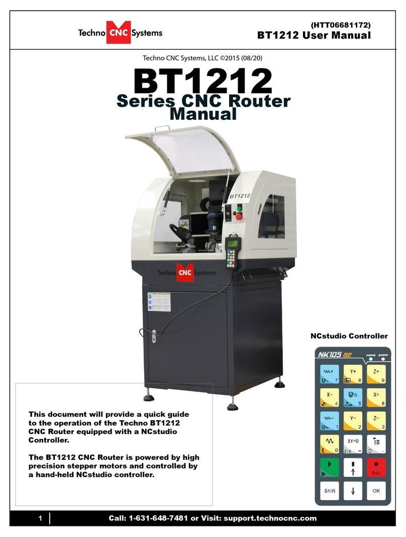
Techno CNC Systems Titan NK105G3 User manual

1Call: 1-631-648-7481 or Visit: support.technocnc.com
Titan Series Manual
NK105G3
Techno CNC Systems, LLC ©2019
This document will provide a quick guide to the set up and operation of the Techno Titan Series
CNC router equipped with the NCstudio G3 controller.
TITA
N
Series CNC Router Manual

2Call: 1-631-648-7481 or Visit: support.technocnc.com
Titan Series Manual
NK105G3
TABLE OF CONTENTS
Forklift Guide ............................................................. Page 3
Safety Instructions ............................................................. Page 4
Colleting Guidelines ............................................................. Page 5
1. Techno Titan Series Quick Setup ........................................... Page 6
Techno Titan Series Installation ..........................Page 7
2. Vacuum Pump Installation ............................................ Page 10
3. Enabling the Titan Series ............................................ Page 11
4. Titan Series Start Up ............................................ Page 12
5. NK105G3 Controller ............................................ Page 13
Single Keystroke Functions ............................................ Page 14
Movement Keys ........................... Page 15
Shift Commands / Combination Keystrokes ........................... Page 16
Execution Keys and Menu Navigation ........................... Page 17
6. Operating Tutorials
6.1- Switching Movement to Step or Jog ......... Page 18
6.2- Jogging the Machine and Changing from High/Low J Page 18
6.3- Stepping the machine ........................... Page 18
6.4- Modifying the Jog Speed and Step Size ........................... Page 19
6.5- Feedrate Override ........................... Page 19
6.6- Adjusting the XYZ Position/WCS/User Origin ......... Page 20
6.7-LoadingaG-codele .............................................Page21
6.8- Running a G-code File ........................... Page 22
7. Advanced Tutorials
7.1- Alternating bet. Override/Programmed Feedrates ..............Page 23
7.2-SettingOverridespeedforaG-codele .............Page24
7.3- Manually Changing Tools ............. Page 26
7.3.1- Removing and Inserting tools into the Spindle ............. Page 26
7.3.2- Using The Automatic Toolchanger Function ............. Page 27
7.3.3- Tool Change Parameters and Settings ............. Page 28
7.4- Setting Tool Lengths ............. Page 29
7.4.1- Tool Length Measuring Settings ............. Page 29
7.5 How to use the 6 work coordinates ................................................. Page 30
7.6 How to use the Select functions ................................................. Page 31
4th Axis Rotary Table Set Up ................................................... .Page 32
8. Maintenance Information
8.1- Lubricating the X-Y Rack and Pinion .............. Page 33
8.2- Lubricating the X-Y-Z Rails .............. Page 33
8.3- Lubricating the Z Ballscrew .............. Page 34
8.4- Recommended Lubricants ................. Page 34
Parameter and Settings .................................................................... Page 35 - 40
Notes on G-Code .....................................................................Page 41
Becker Vacuum Pump Information ...................................................Page42-49
Troubleshooting .....................................................................Page 50
Warranty .....................................................................Page 51

3Call: 1-631-648-7481 or Visit: support.technocnc.com
Titan Series Manual
NK105G3
Techno CNC Systems Titan
Series Forklift Guide
SAFETY WARNING:
DO NOT LIFT MACHINE OR MOVE
MACHINE BY THE GANTRY
For safety and to prevent damage to the machine, Lift Machine Using The Forklift Tubes or Frame
ONLY
** The side of the Titan Series CNC Router may NOT have forklift tubes. Make sure forklift blades
enter through the frame of the machine only. Use blocks when lifting machine to prevent
damage to the vacuum table plumbing **
Install Leveling Feet When
Placing Machine
Cable Carrier Tray May Not Be Bolted To Frame. This SHould Be
Completed When Machine is Elevated
LIFT TITAN FROM
FRONT
1- a 5000LB CAPACITY OR LARGER FORKLIFT IS
RECOMMENDED
2-ONLY LICENSED FORKLIFT OPERATORS SHOULD
USE FORKLIFT
3-GREAT CARE MUST BE TAKEN WHEN LIFTING
MACHINE TO PREVENT INJURY AND EQUIPMENT
DAMAGE
4-WHEN LIFTING FROM FRONT, PLACE FORKS INSIDE
FORKLIFT TUBES ONLY!
5-MACHINE INCLUDES LEVELING FEET THESE
SHOULD BE INSTALLED WHEN MACHINE IS PUT
IN ITS FINAL DESTINATION
LIFT TITAN FROM
SIDE
1- a 5000LB CAPACITY OR LARGER FORKLIFT IS
RECOMMENDED
2-ONLY LICENSED FORKLIFT OPERATORS SHOULD
USE FORKLIFT
3-GREAT CARE MUST BE TAKEN WHEN LIFTING
MACHINE TO PREVENT INJURY AND EQUIPMENT
DAMAGE
4-IT IS RECOMMENDED TO HAVE FORK LIFE EXTENSIONS.
5- WHEN LIFTING MACHINE FROM SIDE PLACE WOOD BLOCKS
BETWEEN THE FORK AND STEEL FRAME TO PREVENT
DAMAGE TO VACUUM PIPING. GREAT CARE MUST BE
TAKEN WHEN LIFTING FROM SIDE TO PREVENT DAM-
AGE TO WIRING. FORKS MUST EXTEND ALL THE WAY
THROUGH FRAME.
WARNING: WHEN LIFTING FROM SIDE WEIGHT MAY BE
UNBALANCED.
6- MACHINE INCLUDES LEVELING FEET! THESE SHOULD
BE INSTALLED WHEN MACHINE IS PUT IN ITS FINAL
DESTINATION

4Call: 1-631-648-7481 or Visit: support.technocnc.com
Titan Series Manual
NK105G3
1. Keepngers,hands,andallotherobjectsaway
from machine while power is on.
2. Disconnect power to all system components
when not in use, when changing accessories, and
before servicing.
3. Do not loosen, remove, or adjust machine parts or
cables while power is on.
4. Exercise care with machine controls and around
keyboard to avoid unintentional starting.
5. Make sure voltage supplied is appropriate to
specicationsofcomponents.
6. Machines must be plugged into three-pronged
grounded outlets. Do not remove the grounding
plug or connect into an ungrounded extension
cord.
7. Keep cables and cords away from heat, oil, and
sharp edges. Do not overstretch or run them
under other objects or over work surfaces.
8. Useproperxturesandclampstosecurework.
Never use hands to secure work.
9. Do not attempt to exceed limits of machine.
10. Do not attempt to use machine for purposes
other than what is intended.
11. Use machine only in clean, well-lit areas free
fromammableliquidsandexcessivemoisture.
12. Stay alert at all times when operating the
machine.
13. Always wear safety goggles.
14. Donotwearloose-ttingclothingwhen
operating machine. Long hair should be
protected.
15. Always maintain proper balance and footing
when working around the machine.
16. Maintain equipment with care. Keep cutting
tools clean and sharp. Lubricate and change
accessories when necessary. Cables and cords
should be inspected regularly. Keep controls
clean and dry.
17. Before using, check for damaged parts. An
authorized service center should perform all
repairs. Only identical or authorized replacement
parts should be used.
18. Remove any adjusting keys and wrenches before
turning machine on.
19. Do not operate the machine unattended.
20. Follow all safety instructions and processing
instructions in the MSDS for the material being
processed.
21. Use proper precautions with dust collection
systemstopreventsparksandrehazards.
22. Makesuretohaveproperreextinguishing
equipment on hand at all times.
WARNING: IMPROPER OR UNSAFE OPERATION OF THE MACHINE WILL RESULT IN
PERSONAL INJURY AND/OR DAMAGE TO THE EQUIPMENT.
READ THESE INSTRUCTIONS THOROUGHLY BEFORE OPERATING MACHINE. DO
NOT OPERATE MACHINE IF YOU ARE UNFAMILIAR WITH THESE SAFE OPERATING
INSTRUCTIONS. DO NOT OPERATE MACHINE WITHOUT KNOWING WHERE THE
EMERGENCY STOP SWITCH IS LOCATED.
PREVENT FIRE HAZARDS by using the proper feeds, speeds, and tooling while operating your
Techno machine. For example, setting feeds and speeds too low and/or using dull tool bits
createsfriction at the material.Thefriction generatesheatwhich can resultin a re that can
be drawn through the vacuum table or dust collector without warning. Fire hazard from friction
heating caused by dull tools is possible when cutting certain materials, especially composite
material such as wood composites, MDF and Particleboard. © 2012
SafetyInstructions

5Call: 1-631-648-7481 or Visit: support.technocnc.com
Titan Series Manual
NK105G3
WARNING!
THE SPINDLE WILL BE DAMAGED
IF UNBALANCED EQUIPMENT IS USED.
AIR SUPPLY MUST BE FILTERED AND DRY.

6Call: 1-631-648-7481 or Visit: support.technocnc.com
Titan Series Manual
NK105G3
L1 L2 L3
Fig. 1.1
Enclosure
The Techno Titan Series CNC Router is powered by 220 Volt AC. Unless specially requested, the
electronics require 3-phase power.
The Electronics are housed in the large NEMA enclosure
as shown in Figure 1.1. When unpacking the machine avoid
twisting the cable carrier that guides the cables to the
motors.
Haveasuitablyqualied
person connect the 220V
to the shown terminals.
Make sure that all local
electrical codes are obeyed.
For single phase machine,
connect power to L1 and L3
only.
1.1
1.3
I. TECHNO TITAN SERIES QUICK SETUP
Unpack the hand-
held controller
(shown in Fig 1.4)
and carefully
attach this to the
controller board.
(shown in Fig 1.5).
1.4
Fig. 1.4
Fig. 1.3
Guide the cable through the hole
on the side of the enclosure and
attach the hand-held controller to
the DB 15 terminal.
1.5
Fig. 1.5
Open the rear of the controller
using the provided key located
around the emergency stop
button or inside of the tool box.
You will now have access to the
electronics that drive the CNC.
They will be identical or like
depending on the model issued.
(shown in Fig. 1.2).
The terminals for the
220 volt connection are located
at the bottom of the box
(shown in Fig.1.3)
1.2
Fig.
1.2
1.6
If the machine has a vacuum
hold down pump, there is a
matching connector that will
plug into the controller box
(shown in Fig.1.6). Vacuum Starter
Connection
Fig. 1.6

7Call: 1-631-648-7481 or Visit: support.technocnc.com
Titan Series Manual
NK105G3
I.I Techno Titan Series Installation
2.1
Removethecontrollerandplaceitontheoortotheleftofthemachine.
When unpacking the controller, avoid twisting the cable carrier that guides the cables to the motors.
Carefully remove the Titan from its wood pallet. Be sure to remove the bolts from its four leveling feet
insertion holes, as well as anything stowed under the Titan during shipping.
Remove all bubble wrap, foam and strapping from the machine.
Attached the provided leveling feet to the six legs and adjust accordingly until the table is level.
2.1a
Remove the four brackets used to stabilize
the gantry during shipping using metric allen
wrenchs. (Fig. 1.1a)
Fig.1.1a

8Call: 1-631-648-7481 or Visit: support.technocnc.com
Titan Series Manual
NK105G3
2.3
Take the black connector coming from the
Handheldcontroller(g2.3a,)andguideit
through the hole in the side of the control cabi-
net.
Locatethecontrollerboard(g2.3b)andattach
the block connector as shown by the red arrow.
Fig. 2.3a Fig. 2.3b
2.2
Open the back of the controller box (shown in Fig 2.2a) with the key provided. The
electronicswillnowbeexposedandcomponentsidentiedinFig2.2b.
Fig. 2.2a
Fig. 2.2b
A- Controller Board.
B- 24Volt PSU.
C- Stepper Driver.
D- 220Volt In.

9Call: 1-631-648-7481 or Visit: support.technocnc.com
Titan Series Manual
NK105G3
2.4
Haveaqualiedelectricianattach208-230
Volts, 3-phase to the terminal on the bottom
of the box (Fig 2.4.)
Ifthemachinehasbeenmodiedforsingle
phase operation, then L1, L3 and GND are
used, and nothing is attached to L2.
Fig.2.4
2.5
If the machine has a vacuum table, the
Vacuum Pump should be wired to 208-
230V, 3-phase or 440V (depending on what
isspeciedontheUnit,)byaqualied
Electrician. (Fig 2.5a)
Fig. 25a
Fig. 2.5b
Fig. 2.5c
The starter box will have a round silver
connector attached to a grey cable coming
out of it, (Fig 2.5b).
This connector plugs into the socket on the
side of the machine, (Fig 2.5c).
This cable provides 220 volts to the starter
coil to turn on the vacuum.

10 Call: 1-631-648-7481 or Visit: support.technocnc.com
Titan Series Manual
NK105G3
III. Vacuum Pump Installation
Matching connector that will plug into the
controller box (shown left)
WARNING: DirectionofPumpRotationiscritical.BrieystartPumpandcheckrotation
(arrow on casing). Exchange phases if rotation is incorrect. IF YOU RUN THE PUMP/BLOWER
CONTINUOUSLY IN THE WRONG DIRECTION,
THE VANES WILL BE DAMAGED.
NOTE:
The cover was
removed from Motor
Starter.
YouwillneedtohavetheelectricianconnectACpower(208-230V3PH)asspeciedonthe
unit to the Motor Starter at L1, L2, L3 and Ground (PE).
3 Phase Control Box
Pump/Blower Motor
Starter Box & Connector
The starter box will have a round silver
connector attached to a black cable
coming out of it.
This connector plugs into the socket on the
side of the machine,
This cable provides the signal to the starter
coil to turn on the vacuum.
L1,L2,L3

11 Call: 1-631-648-7481 or Visit: support.technocnc.com
Titan Series Manual
NK105G3
Make sure wire conduit
is properly attached as
shown in photos - any
exposed wiring could be
damaged and cause harm
to the machine
Make sure to attach a ground wire from the
ground lug on the back of the machine to a
grounding rod.

12 Call: 1-631-648-7481 or Visit: support.technocnc.com
Titan Series Manual
NK105G3
Once power is connected, turn the machine on by
turning the main power disconnect switch to the
vertical, “ON”, position.
Vacuum Pump ON/OFF
Press the Vacuum Pump button to turn on the vacuum pump. The operator can usually tell by the
sound of the pump whether its rotating in the correct direction due to the sound of the pump. If the
pump sounds like it is clicking and not making a humming noise then it is most likely running in the
wrong direction.
Flow of vacuum from the pump to the table is controlled by the gate valve
button(s) on the front of the machine.
Power is now applied to the controller box. The red light on Power OFF will now light up indicating the
machine is powered, but the controller and motors are not yet enabled.
Tocheckvacuumpumprotationandtestonando,rstensurepowerisconnectedtoboththe
vacuum pump starter box as well as the controller cabinet.
Gate Valve
When the gate valve is pressed, the operator should be able to feel air being pulled through the ports
on the table. Please remove black plugs before operation.
If the air blows out after pressing the “Gate Valve” button, this means that the pump is wired
backwards. Please exchange any two power leads. (Swap L1 with L2)

13 Call: 1-631-648-7481 or Visit: support.technocnc.com
Titan Series Manual
NK105G3
1
A
2345678
1 2 345678
B
C
D
E
F
A
B
C
D
E
F
Dept. Technical reference Created by Approved by
Document type Document status
Title DWG No.
Rev. Date of issue Sheet
11/21/2018
1/1
BP002
Becker Pump Assembly
Bob Valentine
2" NPT Street Elbow
2" NPT x 8" Long Steel Nipple
2" NPT Female Steel Tee Fitting
2" NPT Plastic Angled Barb Fitting
2" NPT x 6" Long Steel Nipple
Secondary Vacuum Pump Filter Unit and Cannister
Becker Pump Vacuum Gauge
2" NPT to 3
8" NPT Reducer w/. 3
8" NPT to 1
4" NPT reducer
2" NPT Closed Nipple

14 Call: 1-631-648-7481 or Visit: support.technocnc.com
Titan Series Manual
NK105G3
Once the main power switch has been engaged the controller is activated by pressing the
green on switch on the front of the controller.
Figure 4.1a shows the buttons and their functions.
Emergency
Stop
Power
Enable
Power
Disable Spindle Inverter
Readout
Vacuum
Pump ON/OFF
USB
Port
Fig. 4.1a
IV. Enabling the Titan Series Machine
Control Panel Functions
4.1
Turn the machine on by turning the
main power control switch to the
upright position (Fig 4.2a)
Fig. 4.2a
Fig. 4.2c
Power is now applied to the
controller box. The red light
will now light up indicating the
machine is powered, but nothing is
enabled such as the controller and
motors(Fig 4.2b)
Press the green button to apply
power to the controller and enable
the motors. (Fig 4.2c)
Fig. 4.2b
(Note that the red POWER button
will remain lit if the Emergency
Stop is pressed during
operation.)
4.2 Powering On
IMPORTANT: DOORS MUST BE CLOSED FOR POWER TO ENABLE.
Open/Close
vacuumow

15 Call: 1-631-648-7481 or Visit: support.technocnc.com
Titan Series Manual
NK105G3
Whenthemachinerstpowerson,
the display on the controller will light
up and say “Starting System”. (Fig.
4.1a)
Once the system has booted it will
ask the user “Back to reference
point?” Fig 4.2b
Fig. 4.1a Fig. 4.2b
Thisisalsoknownas‘homing’themachine.Itreferstotheprocessofthemachinendingitsmechani-
cal home position.
From this point, the user has two options;
Home the machine or cancel the homing process. We recommend that you home the machine every
time you start up.
Press “ESC” will skip the homing process.
WARNING:Therewillbenoreferencepositionandbreakpoints,osetsandall
functions that rely on a reference position will be invalid.
Once the machine has moved to the its home position on each axis, it will stop and enter an IDLE state
and will be ready to use.
You should test all machine functions before beginning to cut. The functions are displayed in the next
section.
Pressing“OK”willinitiatethehomingprocess.Themachinewillrstmovethe
Z-axis to the top of travel and then the X and Y axis will move simultaneously until
both are at the home / reference position at the front left corner of the machine
bed.
NOTE: The homing procedure can be aborted at anytime by pressing ESC.
ADVANCED HOMING:
If you hit “ESC” by accident, or would like to reindicate the axes, there are two ways to “Home” again.
1) Press Menu > 3. Operations > 1. Back REF Point > 1. All Home
2) Shortcut
+
4.3 Titan Startup

16 Call: 1-631-648-7481 or Visit: support.technocnc.com
Titan Series Manual
NK105G3
Handheld Controller Layout
The layout of the NK105G3 handheld controller.
Status
Lights
Execution
Keys
Output
Keys
Movement
Keys
Function
Keys
Menu
&
Navigation
Keys
5. NK105G3 Controller

17 Call: 1-631-648-7481 or Visit: support.technocnc.com
Titan Series Manual
NK105G3
Single Keystroke Functions on the Handheld Pendant

18 Call: 1-631-648-7481 or Visit: support.technocnc.com
Titan Series Manual
NK105G3
Movement Keys
All the movement type keys are colored yellow. They will work in both
Jog and Stepping modes.

19 Call: 1-631-648-7481 or Visit: support.technocnc.com
Titan Series Manual
NK105G3
Shift Commands / Combination Keystrokes
To use the shift commands, you must press and hold the shift key and then select a second key.
When it reads X1 Y1 Z1, that is relative. When it reads X* Y* Z*, that means absolute.

20 Call: 1-631-648-7481 or Visit: support.technocnc.com
Titan Series Manual
NK105G3
Execution Keys and Menu Navigation
Use the arrows to navigate menus, move cursors and in
conjunctionwithotherkeystoperformspecicfunctions.
Controller
Power
Controller
Communication
Job
Running
Spindle
ON
Dust Shroud
Up / Down
Alarm
Chuck
Open / Close
Status Lights and Indicators
Pop Up Pins
Table of contents
Other Techno CNC Systems Cutter manuals
Popular Cutter manuals by other brands

Jenlis
Jenlis Weed Razer Pro product manual
PSI Matrix
PSI Matrix PP 803 installation guide
Hypertherm
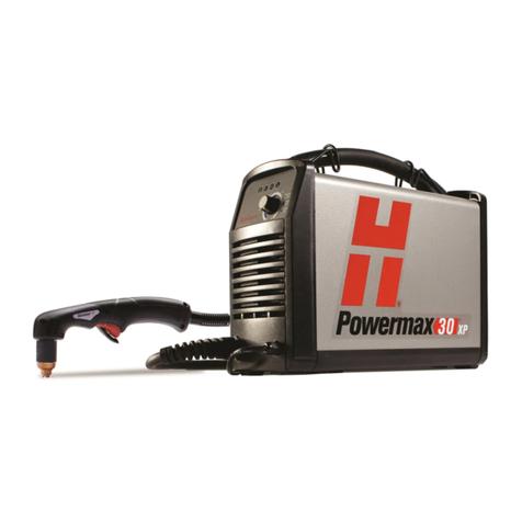
Hypertherm Powermax30 AIR manual

Logan Graphic Products
Logan Graphic Products ARTIST CLASSIC Instruction and operation manual
iWeld
iWeld CUT 85 CNC LCD user manual

Land Pride
Land Pride RCD1884 Operator's manual
