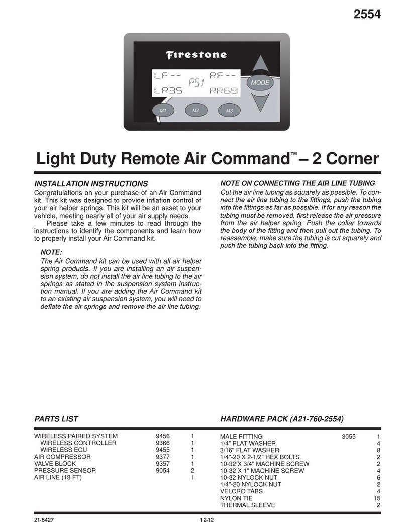
Firestone 2491 User manual

GAUGE PANEL 9369 1
AIR COMPRESSOR 9377 1
VALVE BLOCK 9357 1
PRESSURE SENSOR 9054 2
WIRE HARNESS 9371 1
AIR LINE 0938 1
MALE FITTING 3055 1
TEE FITTING 3025 2
3/16" FLAT WASHER 9
21-8392 07-11 NAD-37281-3
2491
PARTS LIST
INSTALLATION INSTRUCTIONS
Congratulations on your purchase of a Light Duty Elec-
tronic Air Command™ kit. This kit was designed to
provide inflation control of your air helper springs. This
kit will be an asset to your vehicle, meeting nearly all of
your air supply needs.
Please take a few minutes to read through the
instructions to identify the components and learn how
to properly install your Light Duty Electronic Air Com-
mand™ kit.
NOTE:
The Light Duty Electronic Air Command™ kit can be
used with all air helper spring products. If you are
installing an air suspension system, do not install the
air line tubing to the air springs as stated in the sus-
pension system instruction manual. If you are add-
ing the Light Duty Electronic Air Command™ kit to
an existing air suspension system, you will need to
deflate the air springs and remove the air line tubing.
NOTE ON CONNECTING AIR LINE TUBING
Cut the air line tubing as squarely as possible. To con-
nect the air line tubing to the fittings, push the tubing
into the fittings as far as possible. If for any reason the
tubing must be removed, first release the air pressure
from the air helper spring. Push the collar towards the
body of the fitting and then pull out the tubing. To reas-
semble, make sure the tubing is cut squarely and push
the tubing back into the fitting.
1/4" FLAT WASHER 4
1/4"-20 X 2-1/2" HEX HEAD BOLT 2
10/32" X 3/4" MACHINE SCREW 1
10/32" X 1" MACHINE SCREW 4
1/4"-20 NYLOCK NUT 2
10/32" NYLOCK NUT 5
VELCRO TABS 4
NYLON TIE 15
Light Duty Electronic Air Command™
TOOLS REQUIRED:
CENTER PUNCH 3/16" DRILL BIT
9/32" DRILL BIT 3/8" DRILL
WIRE CRIMPERS 3/8" WRENCH
1/2" WRENCH 5/8" WRENCH
7MM WRENCH PHILLIPS SCREWDRIVER
PSI
BAR

TO AIR SPRINGS
(SOLD SEPARATELY)
TERMINAL NUTS
(TIGHTEN FINGER TIGHT)
Figure “A”
GREY
VALVE BLOCK
PRESSURE
SENSORS
WIRE HARNESS &
CONNECTOR
AIR LINE
PSI
BAR
LF/LR RF/RR
VIOLET
RED
(IGNITION +)
BLACK
(BATTERY -)
BLUE
RED
System Operation
Push the up or down button to set the air springs to the desired
pressure. After the button is released, the system will inflate or deflate
to the set pressure. The system may make periodic adjustments to
maintain the set pressure. The system will not deflate below 5 PSI and
will not inflate past 120 PSI. If the system pressure is above or below
these levels, a warning will be displayed. To change the display values
from PSI to BAR, or BAR to PSI, press and hold both the up and down
buttons, on the right side, at the same time.
RED
BLACK
(GROUND)
COMPRESSOR
BROWN
GREEN
RED/BLUE

Figure “B”
STEP 1—MOUNT THE COMPRESSOR
Begin by removing the negative battery cable. Select a conve-
nient location to mount the compressor. This location should
provide ample air flow and be protected from airborne debris
and moisture. The mounting surface should be rigid to sup-
port the compressor. The compressor is oil-less and can be
mounted in any orientation necessary for installation. Make
sure that the wire harness will reach form the compressor to
the anticipated location of the gauge panel. Install a male fitting
into the treaded output port on the compressor head, see Fig-
ure “A”. Tighten the fitting sufficiently to engage at least two
threads with the pre-applied thread sealant. DO NOT OVER
TIGHTEN THE FITTING. Mark the four compressor mounting
holes using the compressor as a template and a center punch,
then drill four 3/16” holes. Mount the compressor using the
supplied 10-32 x 1” machine screw, 10-32 nylock nuts and
3/16” washers. See Figure “B”. Attach the black wire from
the compressor to a convenient ground source on the vehicle.
STEP 2—MOUNT THE MANIFOLD BLOCK
Select the valve block from your kit and install the pressure
sensors into the top of the valve block in the holes marked
PS1 and PS2. See Figure “A”. Select a convenient location
to mount the valve block near the compressor. Mark the two mounting holes using the valve block as a template
and a center punch, then drill two 9/32” holes. Mount the valve block using the supplied 1/4”-20 x 2-1/2” bolts
and 1/4” nylock nuts.
STEP 3—WIRE HARNESS FORM THE COMPRESSOR AND VALVE BLOCK
Insert the red/blue wire from the wire harness with the male spade terminal into the female spade terminal on the
red wire from the compressor. The other red wire in the wire harness with the fuse will be connected to a 12 Volt,
20 Amp positive power source. See Figure “A”. Attach the brown and green wires with ring terminals from the
wiring harness to the studs on the pressure sensor in RF/RR, and the violet and grey wires with ring terminals from
the wiring harness to the studs on the pressure sensor in LF/LR. Tighten the nuts on the pressure sensor terminals
figure tight. DO NOT OVERTIGHTEN THE TERMINAL NUTS. See Figure “A”.
STEP 4—MOUNT THE GAUGE PANEL
The gauge panel must be mounted in a dry protected location with a flat mounting surface. Install the four Velcro
tabs ontp the back of the gauge panel and then firmly place the gauge panel onto the mounting location.
STEP 5—WIRE HARNESS FOR THE GAUGE PANEL
Connect the black wire from the gauge panel wire harness to a suitable ground and the red wire to 12V ignition
activated source. Route the wire harness from the compressor and manifold block to the gauge. Use the Nylon ties
provided to secure the wire harness to the vehicle. Route the wire harness to avoid direct heat from the exhaust
system and away from any sharp edges. Insert the male connector into the female connector until a clicking noise
is heard. See Figure “A”.
STEP 6—ROUTE THE AIR LINE
Cut a section of air line tubing that will reach from the compressor to the valve block. Cut the air line tubing as
squarely as possible and insert the tubing into the male fitting on the compressor and then into the fitting on the
valve block marked IN. Cut a section of air line tubing that will reach from the valve block to one of the air springs.
Cut the air line tubing as squarely as possible and insert the tubing into the fitting on the valve block and then insert
the other end into the air spring. Use the Nylon ties provided to secure the air line tubing to the vehicle. Route the
tubing to avoid direct heat from the exhaust system and away from any sharp edges. Repeat this last step on the
other air spring and remaining fitting.
STEP 8—CHECK THE SYSTEM
With the Light Duty Electronic Air Command™ kit and the air springs installed you are ready to test the system.
Re-attach the negative battery cable. Turn on the vehicle’s ignition. Push and hold the up button to inflate the air
springs. The gauge will display how much air pressure is in the system. Inflate the air springs to 70 psi or the max
air spring pressure, which ever is less, and check the fittings for air leaks with a solution of soap and water. If a leak
is detected at a tubing connection, check to make sure that the tube is cut as squarely as possible and that it is
pushed completely into the fitting. The tubing can easily be removed from the fitting by first releasing the pressure
from the air spring, then by pushing the collar towards the body of the fitting and holding, then pulling the tube out.

www.ride-rite.com
TROUBLE SHOOTING THE SYSTEM
Display powers up but it will not inflate or deflate — The red power wire in the wire harness is not connected
to the battery.
Both sides blink “Hi” & “150” repeatedly and will not inflate or deflate — Two of the wires for the pressure
senders are switched. Gray and Violet go to the LF/LR sender. Brown and Green go to the RF/RR sender.
One side blinks “Hi” & “150” repeatedly and will not inflate or deflate but the other side works — One of the
wires for the pressure sender on that side is not connected/making contact with the pressure sender.
The compressor runs continuously, while one side deflates and the other side does nothing, and the but-
tons on the controller do not respond — The colored wires on the pressure senders are connected to the wrong
pressure sender. Gray and Violet go to the LF/LR sender. Brown and Green go to the RF/RR sender.

Do Not Return This Product
to the Dealer or Distributor
If you are
• missingparts,
• experiencinginstallationproblems,or
• havetechnicalconcernsregardingthisproduct,
you may contact a Firestone Technical Service Representative at [email protected] or at 800-888-0650 (option 1, and
then option 2). Representatives are available from 7:30 a.m. – 4:30 p.m. Eastern on Monday – Friday, excluding holidays.
If you are located outside of the United States, you should rst contact your distributor or dealer directly with any issues.
When contacting Technical Service, please have the kit or part # ready, along with the make, model, and year of the vehicle.
You may also need to provide details, such as 2WD/4WD or if the vehicle has been lifted or lowered from stock height.
If you have a warranty concern, please include in your email a detailed description of the situation, a photo(s) of the
issue, and your contact information, including ship-to address.
WARRANTY COVERAGE*— The Ride-Rite™ kits, components, and accessories are warranted against defects in
workmanship and materials. This warranty does not cover service or labor charges, neglect…to the product.
PERIOD OF COVERAGE:
• Ride-Rite air springs – Lifetime Limited • Work-Rite load assists – 2 Years Limited
• Sport-Rite air springs – Lifetime Limited • Air-Rite accessories – 2 Years Limited
• Coil-Rite air springs – Lifetime Limited • Brackets, hardware, ttings, air line, and other
• Level-Rite air springs – Lifetime Limited components – 2 Years Limited
HOW TO MAKE A WARRANTY CLAIM — If you purchased your air springs in the U.S. or Canada and believe
you have a part with a warrantable defect, call Firestone directly at 1-800-888-0650.
International customers should contact their distributors or dealers directly with any problems.
(*) Please refer to the “Firestone Limited Lifetime Air Spring Warranty” for details, terns, and conditions.
21-8387 01-13 NAD-37143-1

FIRESTONE LIMITED LIFETIME AIR SPRING WARRANTY
Firestone Industrial Products Company LLC (“Firestone”) warrants that its Ride Rite Air Spring Assembly will perform
according to the manufacturer’s specifications for as long as the vehicle on which the system was originally installed
is owned by the original retail purchaser. This limited warranty does not include installation or other service charges
for replacement.
Warranty Period
The Air Spring is warranted for as long as the original purchaser owns the vehicle on which it was originally
installed. The fasteners and upper and lower brackets which accompany the air spring are warranted for a period
of twenty-four (24) months or 24,000 miles whichever occurs first. This warranty begins on the original retail
delivery date.
What is Covered
Any implied warranties are limited in duration to the coverage period of this warranty (some states do not allow
limitation on how long an implied warranty lasts so the above limitation may not apply to you). This Warranty runs
in favor of the original retail purchaser when the Ride Rite Air Spring Assembly is used under normal operating
conditions according to Firestone’s specifications and installed on the appropriate application. This warranty does not
apply to Ride Rite Air Spring Assemblies that have been improperly applied, improperly installed, used in racing or off
road applications or used for commercial purposes. In addition, the warranty will not apply to products which have
not been maintained and serviced according to the instructions that accompany the air spring assembly. The
consumer will be responsible for any costs incurred in removing the product from the vehicle and the cost to return
the air spring assembly to the dealer or installer from which it was purchased. If it is determined that the Ride Rite
Air Spring Assembly failed as a result of a manufacturing defect, Firestone will repair or replace, at its option, any
product or components subject to this warranty. You should retain a copy of your contract with your installer and
your receipt as proof of the date of installation. This warranty is non-transferable and is not assignable in any way.
Firestone specifically excludes any obligation for consequential damages or incidental expenses including claims for loss of use of
the product, loss of time, inconvenience, or commercial loss. This warranty gives you specific legal rights. You may also have other
rights that may vary from state-to-state. Some states do not allow limitations on how long an implied warranty lasts or allow the
exclusion or limitation of incidental or consequential damages. The above limitation or exclusion may not apply to you. There are
no warranties, express or implied, including implied warranty of merchantability and fitness which extend beyond this warranty.
Table of contents
Other Firestone Control System manuals