ECOFOREST Gama ecoGEO HP GEN3 User manual
TECHNICAL MANUAL
CONTACTO DEL SAT:
MODELO:
EN
Gama ecoGEO HP GEN3


Contents
1. General Information ...............................................................................................................................................................5
1.1. Safety considerations.............................................................................................................................................................5
1.2. Disposal..................................................................................................................................................................................7
2. Heat pump installation ...........................................................................................................................................................8
2.1. Transport and handling..........................................................................................................................................................8
2.2. Dimensions and connections .................................................................................................................................................8
2.3. Unpacking ............................................................................................................................................................................10
2.4. Assembly and disassembly of the covers.............................................................................................................................10
2.5. Recommended positioning ..................................................................................................................................................12
2.6. Service areas ........................................................................................................................................................................13
3. Hydraulic installation............................................................................................................................................................ 14
3.1. General instructions.............................................................................................................................................................14
3.2. Brine circuit..........................................................................................................................................................................14
3.3. Heating / Cooling circuit.......................................................................................................................................................15
4. Filling and discharge circuits ................................................................................................................................................. 19
4.1. Filling the production circuit (heating, cooling, DHW and pool) ..........................................................................................19
4.2. Filling the brine circuit .........................................................................................................................................................19
5. Electrical system ................................................................................................................................................................... 21
5.1. General instructions.............................................................................................................................................................21
5.2. Heat pump power supply.....................................................................................................................................................25
5.3. External protections.............................................................................................................................................................27
5.4. Outside temperature probe.................................................................................................................................................27
5.5. External storage systems .....................................................................................................................................................27
5.6. External production equipment...........................................................................................................................................27
5.7. Simultaneous production.....................................................................................................................................................28
5.8. DG1 –SG5 Outlet Units........................................................................................................................................................28
5.9. External auxiliary equipment ...............................................................................................................................................29
5.10. Alarm signal .........................................................................................................................................................................29
5.11. Remote services production control....................................................................................................................................29
5.12. Inside environment control..................................................................................................................................................30
5.13. Remote control by BUS........................................................................................................................................................32
5.14. Energy meter .......................................................................................................................................................................32
6. Start-up ................................................................................................................................................................................ 33
7. Technical specifications ........................................................................................................................................................ 34
7.1. Component location ............................................................................................................................................................34
7.2. Powercircuit diagram...........................................................................................................................................................37
7.3. Electrical connection tables .................................................................................................................................................38
7.4. Load losses...........................................................................................................................................................................41
8. Operation map ..................................................................................................................................................................... 42
9. Operation curves .................................................................................................................................................................. 43
10. Technical data table.............................................................................................................................................................. 46

Technical manual ecoGEO HP
4
EN
11. Symbols................................................................................................................................................................................ 50

Technical manual ecoGEO HP
5
EN
1. General Information
This manual contains the necessary information to install the heat pump. Read this manual carefully before installing the equipment.
Keep this manual handy for future reference.
This manual contains two different kinds of warnings that should be heeded.
NOTE
▪Indicates a situation that may cause material damage or malfunctioning of the equipment. May also be
used to indicate practices which are recommended or not recommended for the equipment.
DANGER!
▪Warning of imminent or potential danger which, if not avoided, may result in injury or even death.
May also be used to warn of unsafe practices.
ecoGEO heat pumps are designed to function within heating systems, cooling systems, for the production of domestic hot water
(DHW), pool heating or other similar uses. The manufacturer is not responsible for any material damage and/or personal injury
resulting from improper use or incorrect installation of the equipment.
The heat pump must be installed by a licensed installer in accordance with applicable local regulations and in accordance with the
installation instructions described in this manual.
1.1. Safety considerations
The detailed instructions in this section cover important aspects for your safety; as such they must be strictly complied with.
DANGER!
▪All the installation and maintenance work described in this manual must be performed by an authorised
engineer.
▪Children shall not play with the heat pump.
▪Cleaning and user maintenance shall not be made by children without supervision.
▪Improper installation or use of the equipment could cause electrocution, short circuits, leakage of
working fluids, fire or other personal injury and/or material damage.
▪If you are unsure of the procedures for installation, maintenance or use of the equipment, contact your
local dealer or technical support for advice.
▪If you detect a malfunction in the unit, contact your local dealer or technical support to answer any
questions.
▪When carrying out installation, maintenance or commissioning of the heat pump, always use
appropriate personal protective equipment.
▪Keep the plastic bags included in the packaging out of the reach of children, as they could result in injury
through asphyxia.
Technical manual ecoGEO HP
6
EN
Refrigerant
The heat pump uses R410A refrigerant as operating fluid. This refrigerant is not harmful to the environment as it does not contain
chlorine, and therefore does not contribute to the destruction of the ozone layer. Under normal operation of the heat pump the
toxicity of the refrigerant is nil and there is no risk of explosion. However, the following precautions should be taken in the event of
refrigerant leakage.
DANGER!
▪The refrigerant contained in the heat pump should not be released in the atmosphere, since it
contributes to global warming of the planet (GWP = 1725).
▪The refrigerant should be recovered for recycling or elimination according to current legislation.
▪Do not directly touch the area where the leak has occurred, as this could result in severe frostbite
injuries.
▪Ventilate the area immediately.
▪Anyone who has come into contact with refrigerant vapour must evacuate the area immediately and
breathe fresh air.
▪Direct exposure of the refrigerant to a flame produces toxic gas. However, this gas can be detected by
its odour when at concentrations well below the permitted limits.
Hydraulic installation
Installation and subsequent interventions on the heating, brine or DHW circuits must only be performed by authorised personnel in
accordance with applicable local regulations and the instructions provided in this manual.
DANGER!
▪Do not touch any of the internal components during or immediately after heat pump operation; this
can result in burns caused by cold or heat. If these components need to be touched, allow sufficient time
for the temperatures to stabilise and wear protective gloves to avoid injury.
Water quality
Be aware of how the DHW circuits and tank of the heat pump react to corrosion. If you are not sure about the quality of the water
available for filling the system, analyse it. In the following tables you can check the water quality level requirements for the production
and brine circuit.
Water components
Concentration in mg/l
Water components
Concentration in mg/l
Alkalinity
HCO3¯< 70
Free carbon dioxide
CO2 < 5
Sulphur
SO42¯< 70
Nitrate
NO3¯< 100
Alkalinity / Sulphur
HCO3¯/SO42¯> 1
Iron
Fe < 0.2
Ammonium
NH4 < 2
Aluminium
Al < 0.2
Free chlorine
Cl2 < 1
Manganese
Mn < 0.1
Hydrogen sulphur
H2S < 0.05
Chloride
Cl¯< 300
Table 1.1. Concentration limits of water elements for production and brine circuits.

Technical manual ecoGEO HP
7
EN
Water properties
Limit values
pH
7.5 < pH < 9
Hardness
4 < °dH < 8.5
Electrical conductivity
10 < µS/cm < 500
Table 1.2. Water property limits for production and brine circuits.
DANGER!
▪Risk of damage due to unsuitable water.
▪Deposits caused by the use of unsuitable water can damage the brine source, the pipes, the heat
exchangers and the DHW tank of the heat pump.
▪The use of sea water is not permitted.
▪The quality of the drinking water must comply with the applicable regional regulations and the
instructions in this manual.
Electrical system
Any intervention on the electrical system must only be performed by an authorised electrician in accordance with applicable local
regulations and the instructions provided in this manual.
DANGER!
▪Remember that the heat pump has multiple external power supply.
▪The heat pump must be supplied with an external switch that can shut off all the circuits. Ecoforest
recommend installing one external automatic breaker in each external power supply (control, internal
auxiliary equipment and drive).
▪Before performing any operation on the electrical panel, disconnect the power supply.
▪During installation and maintenance of the equipment never leave the electrical panel unattended
while it is exposed.
▪Do not touch any component of the electrical panel with wet hands as this could cause an electric
shock.
1.2. Disposal
This device should not be treated as household waste.
At the end of its useful life, dispose of the device properly in accordance with local regulations and in an
environmentally friendly way.
The heat pump uses R410A refrigerant in its circuit. This refrigerant is not harmful to the environment, but once its useful life cycle
has finished, the refrigerant must be recovered and recycled or disposed of according to current regulations.
The heat pump cannot be disposed of with household waste when its useful life ends. Carry out the elimination of the appliance in
accordance with the pertinent local regulations, in a correct and respectful way with the environment. Put the product at the end of
its useful life in the hands of the waste manager authorized by the local authorities for transport to an appropriate treatment plant.

Technical manual ecoGEO HP
8
EN
2. Heat pump installation
2.1. Transport and handling
The heat pump must be transported vertically and not exposed to adverse weather conditions. It can be lain carefully on its rear side
to facilitate transportation to the installation site.
NOTE
▪Do not tilt the heat pump more than 45º, since this could impair proper equipment operation.
▪Due to its heavy weight, the heat pump should be handled by two workers using a forklift for heavy
loads.
2.2. Dimensions and connections
The overall dimensions and hydraulic connections of the ecoGEO HP 12-40 and ecoGEO HP 15-70 heat pumps are described below.
Figure 2.1. Overall dimensions and hydraulic connections of the ecoGEO HP 12-40 and ecoGEO HP 15-70 models (Amounts in mm).
1062
276
645
165
705
1063
870
750
785
164
705
1062
276
645
165
705
1063
870
750
785
1
2
3
4
5
6

Technical manual ecoGEO HP
9
EN
The overall dimensions and hydraulic connections of the ecoGEO HP 25-100 heat pump are described below.
Figure 2.2. Overall dimensions and hydraulic connections of the ecoGEO HP 25-100 model (Amounts in mm).
No
ecoGEO HP1
ecoGEO HP3
1
Heating supply / heat dissipation
Heating / cooling supply
2
Heating return / heat dissipation
Heating / cooling return
3
Brine / cooling supply
Brine supply / heat dissipation
4
Brine / cooling return
Brine return / heat dissipation
5
Power cables inlet
6
Control cables inlet
No
ecoGEO HP 12-40
ecoGEO HP 15-70
ecoGEO HP 25-100
1
G2” Male
G2” Male
G2-1/2” Male
2
3
4
Table 2.1. Overall hydraulic connections of the ecoGEO HP.
1063
950
276
645
169
783
850
886
1063
950
276
645
169
783
850
886
1
2
3
4
5
6

Technical manual ecoGEO HP
10
EN
2.3. Unpacking
To unpack the heat pump, remove the wooden box carefully, remove the pallet anchoring screws and perform a check to make sure
the heat pump has not been damaged during transportation.
Figure 2.3. Removing the screws fastening the heat pump to the pallet.
2.4. Assembly and disassembly of the covers
A 4 mm allen wrench is needed to assemble and disassemble the covers.
ecoGEO HP Models
1. Disassemble the top front cover. Remove the front and top screws. Pull the cover upwards.
2. Disassemble the bottom front cover. Remove the screws located at the upper part and pull upwards.
3. Disassemble the side covers. Remove the fastening screws and remove the cover.
Anchoring studs to the pallet

Technical manual ecoGEO HP
11
EN
Figure 2.4. Disassembly of the covers of the ecoGEO HP models.
NOTE
▪During cover disassembly, take care to remove the control panel cable without damaging it.

Technical manual ecoGEO HP
12
EN
2.5. Recommended positioning
Choose a dry place where there is no risk of frost. Avoid installation against bedroom walls or walls of other rooms where noise
emissions can be annoying. If possible, install the heat pump with the rear part pointed toward an exterior wall. Avoid installation
near a corner, since this can amplify noise emission levels.
The heat pump should be installed on a stable base that can support the total weight of the equipment and the operating fluids in its
interior. Use the adjustable legs to compensate for possible irregularities on the supporting surface.
Figure 2.5. Positioning and levelling the heat pump.
NOTA
▪Use the eyebolts provided with the heat pump to move the equipment to its final destination.
DANGER!
▪Advertising: The ecoGEO heat pumps are IP20. This means its installation in high humidity conditions
(laundries, saunas, ...) is forbidden.

Technical manual ecoGEO HP
13
EN
2.6. Service areas
The minimum recommended distances to be left around the heat pump to facilitate installation, start-up and maintenance work are
indicated below.
Figure 2.6. Minimum recommended service areas around the heat pump (amounts in mm).
300
300
500
600
300

Technical manual ecoGEO HP
14
EN
3. Hydraulic installation
NOTE
▪The installation schemes included from here on should be considered simply as a guide.
▪The design of the hydraulic installation must be performed by qualified personnel and in accordance
with applicable local regulations.
▪The design of the hydraulic system must ensure at all times the minimum required flow through the heat
pump, otherwise, could cause malfunction of the equipment and even rupture.
3.1. General instructions
The following recommendations should be taken into consideration for proper hydraulic installation.
▪Avoid excessive strain between the pipes and the heat pump connections to prevent leaks and/or transmission of vibrations.
Flexible hoses should be used for heat pump connections.
▪Install cut-off valves at all the hydraulic connections to facilitate future maintenance tasks.
▪Install traps at all the installation points where air pockets can form.
▪Place heat insulation on all circuit pipes to prevent unnecessary heat loss. Pay special attention to the heating insulation on
the brine circuit pipes, since these can reach temperatures below 0ºC, causing condensation and/or frost.
DANGER!
▪During installation work on the hydraulic circuits, take special care to prevent liquid from spilling on
the internal electrical heat pump components, which could cause personal injury due to electrocution
and/or poor equipment operation.
▪Do not install components that might cover the inlet or outlet of the safety valves; this could lead to a
risk of some of its components breaking and cause injuries and/or material damage.
3.2. Brine circuit
The ecoGEO heat pumps can be used with horizontal or vertical (A) geothermal brine systems or by using groundwater (B).
DANGER!
Carefully check the antifreeze concentration of the working fluid. Do not use automatic fill valves or other
items that can change the concentration of the working fluid. Inadequate concentration of the working
fluid could cause malfunction of the equipment and even rupture.
Geothermal brine systems
Brine systems with more than one circuit must be connected in parallel, so the flow rate through each one is similar.
Groundwater brine systems
Groundwater brine systems must use a midway exchanger to prevent the heat pump evaporator from corrosion, freezing or getting
dirty.
DO1
A)
B)
3
4
3
4
DO1
AO1

Technical manual ecoGEO HP
15
EN
Figure 3.1. Brine circuit connection options.
Installation instructions
Follow the instructions below to wire the brine circuit.
▪Install the necessary components to carry out the filling/discharge of the return pipe.
▪Install a particulate filter in the return pipe with a mesh size no greater than 1 mm. It is recommended to install shut off valves
immediately before and after the filter to make it easier to clean or replace.
▪Install a safety unit (expansion vessel + safety valve) in the suction part of the circulator pump to protect the circuit from
overpressure.
▪Adjust the pressure of the expansion vessel to make sure that the circuit remains pressurised at all points.
▪Brine circuit pressure should be between 0,7 and 5 bar (pressure gauge) (70 and 500 kPa).
▪Use a working fluid with a freezing point of at least 10ºC below the minimum nominal working temperature of the equipment.
▪Configure the equipment with a protection of at least 5ºC above the freezing temperature of the working fluid.
3.3. Heating / Cooling circuit
The ecoGEO HP heat pumps can be connected to various types of heating / cooling systems, both directly and by separating buffer
storage tanks. On the other hand, these enable control over several devices that are external to the heating / cooling system directly
from the heat pump's electrical panel.
Heating / cooling system
The ecoGEO HP heat pumps are designed to be used with heating systems with nominal outlet temperatures of up to 55ºC; such as
underfloor heating systems, low temperature radiators or convectors. They are not recommended for use in heating systems that
require higher temperatures.
The ecoGEO HP heat pumps can be used with cooling systems with nominal outlet temperatures of up to 7ºC, such as convectors
and underfloor cooling systems.
Special care should be taken in the design and control in installations with underfloor cooling, to prevent problems of condensation
on floors.
All the models allow control over external passive cooling units.
Direct installation
In simple heating / cooling systems, ecoGEO HP heat pumps can be installed directly into the distribution system, in systems with
underfloor heating, low temperature radiators and convectors.
This configuration makes it possible to simplify the hydraulic installation, reduce costs and space, while optimizing the energy
efficiency of the equipment. However, the design of the hydraulic installation must guarantee the minimum required flow at all times
through the heat pump. For this, the necessary elements must be planned to protect the heat pump in the event of a low flow
situation in the emission system. For this, the installation can be planned to operate with at least one of the emission circuits open
continuously. If all the emission circuits can be closed, it is recommended to install a differential pressure valve between the outlet
and inlet pipes of the heat pump. Other solutions can also be considered, such as the installation of a hydraulic separator between
the heat pump and the emission system, as long as the minimum required flow is guaranteed (see section 10).
Technical manual ecoGEO HP
16
EN
Figure 3.2. Wiring scheme directly to the heating / cooling system (ecoGEO HP3 models).
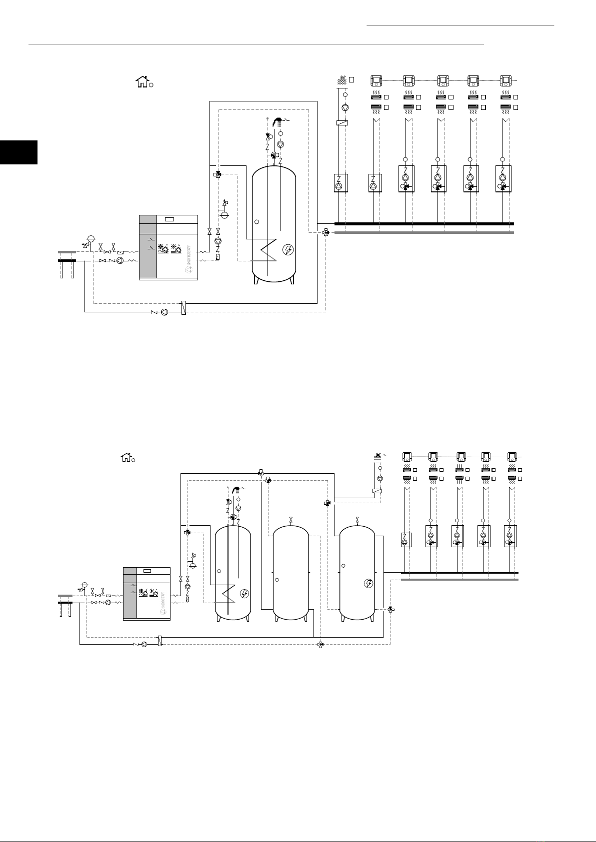
Installation using buffer storage tanks
If required by the application, the heat pump can also be connected to the heating / cooling system using a buffer separator tank. To
do so, it is equipped with two temperature probes that are used to control a buffer storage tank for heating and a buffer storage tank
for cooling. In installations where there is only one buffer storage tank for heating and cooling, both probes have to be installed in
the storage tank. Install the temperature probes at the points where heating / cooling production begins. Heating / cooling production
is stopped by the return temperature probe installed inside the heat pump.
Figure 3.3. Wiring scheme using two buffer storage tanks (ecoGEO HP3 models).
T
T
T
DI4
DO18
DO17
AI11
AI18
AI17
DO4
DO11
DO11
T
TAI20
DO16
DO12 DO12
DO5
P
DO1
DI12
DI11
T
T
DI10
DI9
T
T
DI8
DI7
T
T
DI6
DI5
T
T
DO6
DG1
DO8
AO4
AI14
SG3
DO9
AO5
AI15
SG4
DO7
AO3
AI13
SG2
TT T
M
M
M
DI14
DI13
T
T
T
T
FBus2
DO10
AO6
AI16
SG5
T
M
TAI19
DI1
DI2
EVU
DI3
TAI12
DO3
DO2
AO1
AO2
T
DI4
T
DO17
AI11
T
TAI20
DO12
P
DO1
DI12
DI11
T
T
DI10
DI9
T
T
DI8
DI7
T
T
DI6
DI5
T
T
DO6
DG1
DO8
AO4
AI14
SG3
DO9
AO5
AI15
SG4
DO7
AO3
AI13
SG2
TT T
M
M
M
DI14
DI13
T
T
T
T
FBus2
DO10
AO6
AI16
SG5
T
M
DO5
TAI19
DI1
DI2
EVU
DO4
DI3
TAI12
DO3
DO2
AO1
AO2 DO12

Technical manual ecoGEO HP
17
EN
Figure 3.4. Wiring scheme using one buffer storage tanks (ecoGEO HP3 models).
Outlet units
These can manage as many as five different outlet temperatures. This is done by managing one direct outlet unit and four combined
outlet units. The combined outlet units have to use modulating 3-way valves with an analogue signal of 0-10Vdc. Each outlet unit has
independent terminals for heating and cooling demands. These signals are supplied with 24Vac voltage.
DHW Recirculation
This is used to control activation of the DHW recirculation pump, depending on the temperature recorded in the recirculation line
and the established time schedule.
Pool
This is used to control pool heating production through an intermediate heat exchanger. Pool production can be enabled / disabled
with an external digital input.
Auxiliary equipment integrated in the heating buffer storage tank
This is used to control an auxiliary unit integrated in the heating buffer storage tank. It can be used for normal heat production or as
emergency equipment.
Auxiliary boiler
This is used to control start-up / stop of an auxiliary boiler and regulate final temperature downstream from the boiler by a 0-10 Vdc
modulating 3-way valve. The heat pump can use the boiler to assist in normal heat production or as emergency equipment.
NOTE
▪The hydraulic installation must ensure that while the boiler is operation, the temperature through the
heat pump never exceeds 65ºC, since this could cause serious damage to the refrigerant circuit.
Simultaneous production
This is used to control systems that product heat and cold simultaneously. In these types of installations, the heat pump moves energy
from the cold production system to the various heat production systems and controls both the hot and cold outlet temperature. On
the other hand, it uses modulating valves to detour part of the cold or heat production to the brine system, there by maintaining the
energy balance.
T
T
T
DI4
DO18
DO17
AI11
AI18
AI17
DO4
DO16DO11
T
TAI20
DO12
DO5
P
DO1
DI12
DI11
T
T
DI10
DI9
T
T
DI8
DI7
T
T
DI6
DI5
T
T
DO6
DG1
DO8
AO4
AI14
SG3
DO9
AO5
AI15
SG4
DO7
AO3
AI13
SG2
TT T
M
M
M
DI14
DI13
T
T
T
T
FBus2
DO10
AO6
AI16
SG5
T
M
TAI19
DO2
DO3
TAI12
DI3
DI1
DI2
EVU
AO1
AO2
DO12

Technical manual ecoGEO HP
18
EN
Figure 3.5. Wiring scheme using two buffer storage tanks with simultaneous production (ecoGEO HP1 models).
Installation instructions
Follow the instructions below to connect the heating / cooling circuit.
▪Install a particulate filter in the return pipe with a mesh size no greater than 1 mm. It is recommended to install shut off valves
immediately before and after the filter to make it easier to clean or replace.
▪Check that the volume of the expansion vessel integrated in the heat pump is capable of absorbing any overpressures from
the circuit. If this volume is not enough, install a supplementary external expansion vessel.
▪If necessary, adjust the pressure of the expansion vessel integrated in the heat pump to guarantee that the circuit remains
pressurised at all points.
▪If there is an auxiliary system integrated in the heating storage tank, install a safety valve to protect it from any overpressures.
▪Heating / cooling circuit pressure should be between 0,7 and 2 bar (pressure gauge) (70 and 200 kPa).
T
T
T
DI4
DO18
DO17
AI11
AI18
AI17
T
TAI20
DO16
DO14
DO5
P
DO1
DI12
DI11
T
T
DI10
DI9
T
T
DI8
DI7
T
T
DI6
DI5
T
T
DO6
DG1
DO8
AO4
AI14
SG3
DO9
AO5
AI15
SG4
DO7
AO3
AI13
SG2
TT T
M
M
M
DI14
DI13
T
T
T
T
FBus2
DO10
AO6
AI16
SG5
T
M
DO15
M
M
TAI19
DI1
DI2
EVU
DO4
DI3
TAI12
DO12
DO2
AO2
AO1 DO3

Technical manual ecoGEO HP
19
EN
4. Filling and discharge circuits
DANGER!
▪During filling work on the hydraulic circuits, take special care to prevent liquid from spilling on the
internal electrical heat pump components, which could cause personal injury due to electrocution
and/or poor equipment operation.
4.1. Filling the production circuit (heating, cooling, DHW and pool)
Take the following steps to fill the circuit.
1. Open all the valves of the production circuits.
2. Fill the circuit through the filling valve until the target pressure is reached. Make sure that the pressure does not exceed 3
bar (pressure gauge) under any circumstance.
3. Remove the air from the circuit using the traps installed for that purpose.
4. Check the circuit pressure and repeat the filling process if necessary.
4.2. Filling the brine circuit
The brine system temperature can fall below 0°C, so a mixture of water/antifreeze must be used. It is recommended to use propylene
glycol as an antifreeze additive or ethylene glycol with a corrosion inhibitor. Please check local regulations before using any type of
antifreeze mixture.
When preparing the mixture, be careful to calculate the volume of antifreeze necessary to reach the desired degree of antifreeze
protection. It is recommended to use a mixture with a freezing point at least 10ºC below the nominal minimum temperature.
Brine circuit filling should be done with the filling unit installed in the return pipe and an external circulation pump, taking the
following steps.
1. Prepare the appropriate proportions of antifreeze mixture in external tank A.
2. Connect the external recirculation pump outlet to valve D.
3. Connect a transparent hose from valve E to antifreeze mixture tank A.
4. Close valve C and open filling valves D and E.
5. Start the external recirculation pump and keep it running until the return is completely free of air and the antifreeze mixture
is mixed perfectly.
6. Open valve C and keep the external pump connected to remove the air between valves D and E.
7. Close valve E and pressurise the circuit to target pressure. Make sure that the pressure does not exceed 3 bar (pressure gauge)
under any circumstance.
8. Close valve D.
After completing the brine circuit filling process, it is recommended to check the concentration of antifreeze mixture again using a
refractometer.

Technical manual ecoGEO HP
20
EN
Figure 4.1. Filling the brine circuit.
3
4
DO1
A
B
DE
C
AO1
Table of contents
Other ECOFOREST Control System manuals


Popular Control System manuals by other brands

Simu
Simu TSA Hz 2 Programming manual

Siemens
Siemens SIMATIC HMI ITC1500 V3 PRO Quick install guide

resideo
resideo SmartValve SV9410 installation instructions

Heidolph
Heidolph Intelligent evaporation Hei-VAC Control operating instructions

NAVIS
NAVIS NavDP 4000 Series Operation manual

Laguna Tools
Laguna Tools Smartshop III Series manual

PoLabs
PoLabs PoKeys57CNC Step by step guide - a.k.a. beginners guide

Huawei
Huawei IDS1000 user manual

MASTERZONE
MASTERZONE ZONEFIRST ZONE-ADDER MZA2 Installation and operating instructions

Crestron
Crestron FlipTop FT2 Series quick start

netLiNK Controls
netLiNK Controls netLiNK Controls installation instructions

Fagor
Fagor CNC 8060 LASER Original instructions


