Delta Dual V4 User manual

01992 523523
www.deltamembranes.com
Delta Dual V4/V6 (DMS-217/079)
Installation Instructions
For Ground Water Applications
T.
E.
W.

Delta Dual V4/V6
DDV4V6-M-V1-12.15
Legal information/Copyright
All rights reserved. Contents provided herein must neither be distributed, copied, reproduced, edited or
processed for any other purpose, nor otherwise transmitted, published or made available to a third party
without express written consent from Delta Membranes.
Subject to technical modication without prior notice.
© Delta Membranes 2015

Contents
1.0 Dual V4/V6 Overview 4
2.0 Parts Included 4
2.1 Optional Extras 4
3.0 Discharge Pipework & Fittings 5
4.0 Chamber Overview 6
5.0 Spare Parts 6
6.0 Technical Information 7
7.0 Pump Chamber Depth Limits 8
8.0 Installation Guidelines 9
9.0 Pump Station Location 9
10.0 RC Box Dimensions 9
11.0 Installation of Chamber 10
Section A - Construction of reinforced concrete box 10
Section B1 - Connecting 110mm pipework 11
Section B2 - Connecting perimeter channel to chamber 12
Section B3 - Connecting perimeter channel via a 1.5"/40mm inlet pipe 13
Section C - Connecting discharge and cable duct 14
Section D1 - Backll around chamber with concrete (RC Box) 16
Section D2 - Backll around chamber with concrete (Ground) 17
Section D3 - Backll around chamber with concrete (Reinforced cage) 18
Section E - Installing pumps and high level alarm in chamber 19
12.0 Wiring Diagram 22
13.0 Maintenance 23
14.0 Health and Safety 23
15.0 Guarantee 23
16.0 Troubleshooting 24
17.0 Self Commissioning 25
18.0 Notes 27
Delta Dual V4/V6
For technical support, please call 01279 757400 3

1.0 Dual V4/V6 Overview
Delta Dual V4/V6
The Delta Dual V4/V6 is a packaged pump station designed to collect ground water via perimeter channel or Delta
129 detail and/or clear opening to the top of the chamber - please visit our website for water collection details.
Typically, the Dual V4/V6 would be used to collect ground water from a basement up to 150m² and/or surface water
from a light well up to 12m² to a maximum head of 7m and 9m respectively.
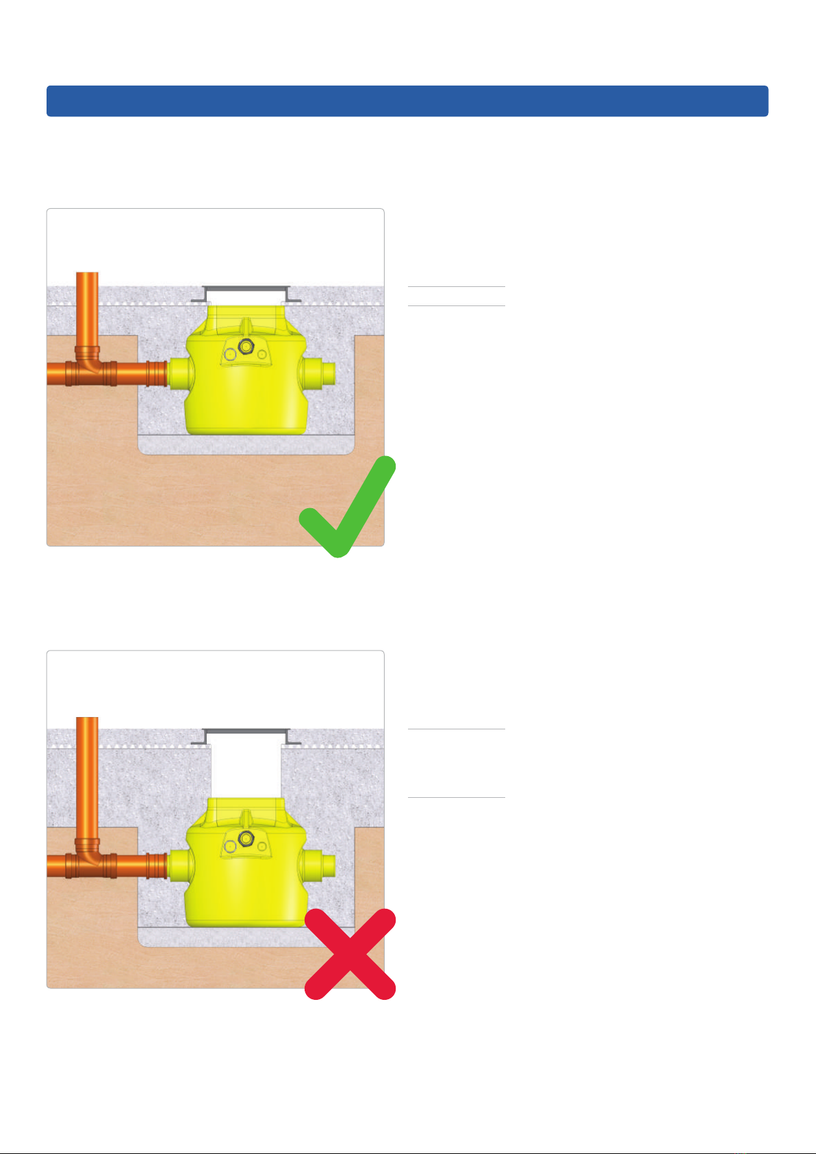
The pump station has been specically designed for below ground applications. The chamber is manufactured from
HDPE and when installed correctly, it is able to withstand hydrostatic forces encountered in high water tables.
The pump station is delivered as a complete package including, the chamber, internal pipework and two powerful
V4/V6 pumps. It is designed to be installed by contractors with competent building, plumbing and electrical skills.
The pumps operate by xed arm oats, the duty pump is set at a standard height (210mm to base of oat) and the
backup pump is set at a high level (380mm to base of oat). The high level alarm (where tted) will operate if the duty
pump fails leaving the backup pump to discharge water.
A high level alarm (DMS-270) is oered as a recommended extra to alert the property occupant when the water level
in the chamber becomes too high. A battery backup (DMS-320) is recommended to power the pumps during power
outage. Please see section 2.1 for more details about optional extras designed for the Dual V4/V6 pump station.
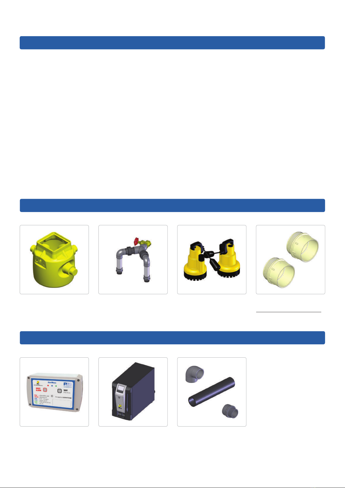
2.0 Parts Included
Chamber - 660 diameter
(902 across spigots) x
800mm deep
1.25” Internal Pipework
4 For technical support, please call 01279 757400
2 x V4/V6 Pumps 2” Discharge Male Iron
for temp. site installation.
2" Cable Duct Male Iron
2.1 Optional Extras
AlertMaxx High Level
Alarm (DMS-270)
2" Discharge Pipework
and various ttings
Power Plus Battery
Backup (DMS-320)

5
Delta Dual V4/V6
3.0 Discharge Pipework & Fittings
Part Description Part No. Qty Req.
2" Pipe - 3m Length (Class E) DMS-0154
2" 90° Elbow - Plain/Plain DMS-0155
2" 45° Elbow - Plain/Plain DMS-0156
2" Socket - Plain/Plain DMS-0157
2" Socket - BSP Mail Thread/BSP Male Thread DMS-0339
2" Male Iron - Plain/BSP Male Thread DMS-0153
2" Male Iron - Plain/BSP Male Thread (Non-pressure) DMS-335
110mm to 2" Adaptor DMS-341
Saddle Clamp - 110mm to 2" (BSP Female Thread) including 1.25" Male Iron DMS-0151
Saddle Clamp - 160mm to 2" (BSP Female Thread) including 1.25" Male Iron DMS-0152
2" Pipe Clip DMS-059
500ml PVC Solvent Cement DMS-0158
Name:
Company Name:
Property Address:
Email:
Phone No.: Mobile No.:
A selection of discharge pipework and ttings are available for the Dual V4/V6 pump station.
Should you require to place an order for any of these items, please complete the form below, scan and email to
Sign: Date:

4.0 Chamber Overview
I
J
K
L
A C E
TO SEWER
H
G
F
B D
Part Description
AInlet Pipe
BConcrete Base
CInspection Cover
DPump Chamber
ECable Duct
FFused Spur
GDistribution Board
HHigh Level Alarm Box
IScreed
JInsulation
KMS20
LBasement Slab
5.0 Spare Parts
Part Description Part No.
1V4/V6 Pump c/w 1.1 & 1.2 DMS-216/084
1.1 Float & Switch Assembly DMS-344
1.2 Non-return Valve DMS-328
2Discharge Arm DMS-326
3‘O’ Ring DMS-132
41.25” Brass Gate Valve DMS-329
5Connector Piece DMS-338
6Connector Adaptor DMS-337
72” Non-pressure Male Iron DMS-335
8Y-piece c/w 2 ’O’ rings DMS-321 1
2
3
8
4
5
6
77
1.1
1.2
6 For technical support, please call 01279 757400
Delta Dual V4/V6

Delta Dual V4/V6
Pump Specication
Pump Type V4 V6
Typical Duty (I/s) Head (m)
33.25 3.75
3.5 3.10 3.60
43.00 3.50
4.5 2.90 3.40
52.75 3.30
62.40 3.00
Power P1(kW) 0.75 1.05
P2(kW) 0.35 0.50
Current (a) 4.00 4.90
Power Phase Single Single
Fuse Spur Rating (a) 13 13
Max. Temperature (°C) 50 50
Weight (kg) 7.17 7.40
Chamber Specication
Chamber Material High Density Polyethnylene - ICO1314 grade
Size (mm) Chamber Diameter 660
Overall Diameter 902 (across spigots)
Depth 800
Volume (L) Below Inlet 137
Total 273
Inspection Cover Not supplied
Clear opening to chamber (mm) 310 x 310
Fixed Inlets 3 x 110 / 160mm
Cable Duct (mm) 50
Vent N/A
Discharge Connection 2" / 50mm BSP Female - External to chamber
Internal Pipework Manifold 1.25" / 32mm BSP Class C
RCBO Rating (a) 16
Cable Length (m) 10
Non-switched Fuse Spur Rating (a) 13
6.0 Technical Information
For technical support, please call 01279 757400 7

7.0 Pump Chamber Depth Limits
< 500mm
> 500mm
The pump chamber must be installed no more than
500mm below oor nishes.
A pump chamber installed more than 500mm below
oor nishes cannot be serviced safely in accordance
with CDM regulations.
If the inlet does not allow the pump chamber to be within depth limits, please contact PPS on 01279 757400 to
discuss chamber options.
Delta Dual V4/V6
8 For technical support, please call 01279 757400

800mm
1200mm
1200mm
8.0 Installation Guidelines
The following instructions are for guidance only and it is the contractor's responsibility to ensure that the
installation is in accordance with the prevailing ground conditions and good building practice, to eliminate any
potential damage to the pump station either during or after installation.
Please read these instructions carefully prior to installing the chamber. If there is anything that is unclear, our technical
help desk is available on 01279 757400.
9.0 Pump Station Location
This station requires routine maintenance, therefore it is important that careful consideration is taken to position the
chamber in a location that allows permanent access to the chamber.
10.0 RC Box Dimensions
Delta Dual V4/V6
For technical support, please call 01279 757400 9

Excavate hole for chamber. Refer to section 10.0 for
RC box internal dimensions.
Lay inlet and discharge pipework. Allow pipework to
protrude into RC box by a minimum of 100mm.
1
3
11.0 Installation of Chamber - Section A
Install re-bar as per structural engineer's drawings.
Pour concrete to form RC box as per structural
engineer's drawings.
2
4
Construction of reinforced concrete box
Delta Dual V4/V6
10 For technical support, please call 01279 757400

11.0 Installation of Chamber - Section B1
Saw o socket end/s, where inlet pipe/s are to
be connected.
Fit push t coupler.
5
7
Position chamber in RC box.
6
Connecting 110mm pipework
Connect inlet pipework to the required chamber spigot.
8
Delta Dual V4/V6
For technical support, please call 01279 757400 11

Mark perimeter channel position on side of chamber.
Cut around the marked line outlining the perimeter
channel using a jigsaw.
9
11
11.0 Installation of Chamber - Section B2
Drill holes in the corners inside the area marked in red.
Insert the perimeter channel into the chamber allowing
35mm of overhang inside the chamber.
10
12
Connecting perimeter channel to chamber
To be followed when installing perimeter channel directly into upper side of chamber.
Delta Dual V4/V6
12 For technical support, please call 01279 757400

11.0 Installation of Chamber - Section B3
Mark position of the 40mm pipe on the side of
the chamber and cut out the marked line using a
1.5"/40mm holesaw.
Saw o 110mm socket end/s to be used.
13
15
Cut 40mm pipe to length allowing an overhang of
35mm inside the chamber.
14
Connecting perimeter channel via a 1.5"/40mm inlet pipe
Attach a DMS-341 adaptor to the 40mm pipe and
connect the adaptor to the chamber via a 110mm
push t coupler.
16
Delta Dual V4/V6
For technical support, please call 01279 757400 13

11.0 Installation of Chamber - Section C
Connecting discharge and cable duct
Wrap the thread on a DMS-0153 high pressure
male iron with PTFE tape.
Apply DMS-0158 high pressure glue around the rst
20mm of the external face of the discharge and cable
duct pipe and internal side of their respective male iron.
17
19
Screw the high pressure male iron into the female iron.
Push discharge and cable duct pipe into their
respective male iron, twisting the pipe as it is pushed
into the male iron to remove any trapped air.
18
20
Delta Dual V4/V6
14 For technical support, please call 01279 757400

11.0 Installation of Chamber - Section C cont.
Ensure a draw cord is pulled through the cable duct as
the cable duct is built.
21
Connecting discharge and cable duct
Delta Dual V4/V6
For technical support, please call 01279 757400 15

11.0 Installation of Chamber - Section D1
Backll around chamber with concrete
To be followed when installing chamber in an RC box.
Check all pipes are connected to the chamber
correctly.
Fill void between RC box and chamber with concrete
(min. C35 grade) or as per engineer's drawings.
22
24
Completely ll chamber with water.
23
Delta Dual V4/V6
16 For technical support, please call 01279 757400

For technical support, please call 01279 757400 17
11.0 Installation of Chamber - Section D2
Fill void between soil and chamber with concrete
(min. C35 grade) or as per engineer's drawings.
26
Completely ll chamber with water.
25
Backll around chamber with concrete
To be followed when installing chamber in the ground.
Allow concrete to cure.
27
Delta Dual V4/V6

11.0 Installation of Chamber - Section D3
Fill void between soil and chamber with concrete
(min. C35 grade) or as per engineer's drawings.
29
Completely ll chamber with water.
28
Backll around chamber with concrete
To be followed when installing chamber in the ground with a reinforced cage.
Allow concrete to cure.
30
Delta Dual V4/V6
18 For technical support, please call 01279 757400

Delta Dual V4/V6
11.0 Installation of Chamber - Section E
Installing pumps and high level alarm in chamber
Pump out water from chamber.
31
Manually remove any debris from chamber and
residual water using a wet vac.
32
Remove discharge arms from 'Y' piece manifold and
screw 'Y' piece on to gatevalve. Ensure gatevalve is
fully open.
33
Wrap PTFE tape around thread located on male irons
at the bottom of the discharge arms and screw
discharge arms on to pumps.
34
For technical support, please call 01279 757400 19

11.0 Installation of Chamber - Section E cont.
Lower pumps in to chamber. Ensure 'O' rings are
correctly seated in unions and screw discharge arms to
'Y' piece manifold.
36
Fill chamber half full with water.
35
Installing pumps and high level alarm in chamber
When installing a high level alarm, refer to the high
level alarm installation instructions.
37
20 For technical support, please call 01279 757400
Delta Dual V4/V6
Pull pump and high level alarm cables through cable
duct.
38
This manual suits for next models
1
Table of contents
Other Delta Water Pump manuals
Popular Water Pump manuals by other brands

KNF
KNF UFK 1.1100 EX installation instructions

BUSCH
BUSCH R 5 0400 B Installation and operating instructions

GORMAN-RUPP PUMPS
GORMAN-RUPP PUMPS S8B1-E100 460/3 Installation, operation and maintenance manual

Grundfos
Grundfos GiM CIU Installation and operating instructions

EasyPro
EasyPro TB Series Instructions for operation

EINHELL
EINHELL GC-DW 1045 N Original operating instructions