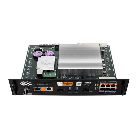
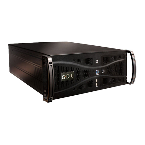
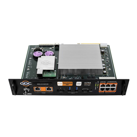
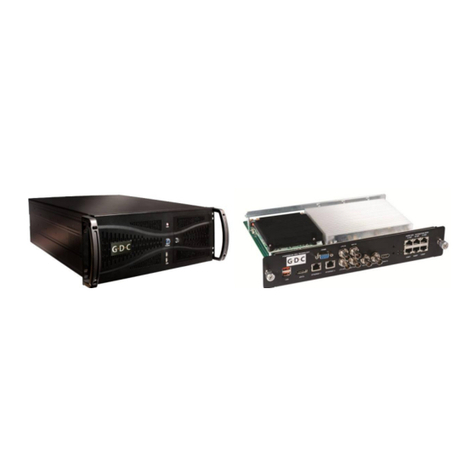
GDC SX-3000 User manual

GDC Technology Ltd
SX-3000
SERVER INSTALLATION MANUAL

SX-3000 Installation Manual
Page 1 of 41
Table of Contents
1 Introduction............................................................................................................................. 3
2 Equipment List......................................................................................................................... 3
3 Installing the GDC SX-3000 Integrated Media Block (IMB) into the projector........................ 4
3.1 Remove existing interface board/placeholders from projector...................................... 5
3.2 Inserting the IMB into the projector ............................................................................... 6
3.2 Projector Network ........................................................................................................... 6
4 External Monitor, Keyboard and Mouse ................................................................................. 7
5 The PSD-3000P External Hard Drive Unit ................................................................................ 7
5.1 Inserting the individual RAID drives into the bay ............................................................ 7
5.2 Connecting the PSD-3000P drive bay to the SX-3000 ..................................................... 8
6 The PSD-3000U External Hard Drive Unit................................................................................ 9
6.2 Inserting the individual RAID drives into the bay............................................................ 9
6.3 Connecting the PSD-3000U drive bay to the SX-3000................................................... 10
7 Operation with PSD-3000U/P................................................................................................ 11
7.1 Importing the RAID Array .............................................................................................. 11
7.2 Selecting the PSD-3000U/P as a Content source .......................................................... 12
8 SX-3000 IP Setup.................................................................................................................... 13
8.1 IMB Network Setup ....................................................................................................... 13
8.2 Projector Connection..................................................................................................... 14
8.3 IMB Marriage and Clearing Door Tampers from the SX-3000 ...................................... 15
9 Series 2 projector setup ........................................................................................................ 17
9.1 Barco Series 2 Projector Setup ...................................................................................... 17
9.2 NEC Series 2 Projector................................................................................................... 18
9.3 Christie Series 2 Projector ............................................................................................. 20
9.4 IMB 3D macro settings changes .................................................................................... 23
10 Time Zone Setup................................................................................................................ 24
11 Content Ingest Management Setup .................................................................................. 25
11.1 Configuring a content ingest source.............................................................................. 25
11.1.2 Content ingest from USB disk.................................................................................... 25
11.1.3 Content ingest from FTP............................................................................................ 26
SX-3000 Installation Manual
Page 2 of 41
11.2 Selecting an ingest source ............................................................................................. 27
12 Audio Setup ....................................................................................................................... 28
12.2 Digital-to-Analog Converters......................................................................................... 28
13 Subtitles............................................................................................................................. 29
14 Automation Setup ............................................................................................................. 30
14.1 General automation setup ............................................................................................ 30
14.2 Adding event labels and actions.................................................................................... 31
14.3 Automation Scheduling ................................................................................................. 32
14.4 Automation setup for server GPIO................................................................................ 33
14.5 Automation setup for projectors .................................................................................. 33
14.6 Automation setup for eCNA devices ............................................................................. 34
14.7 Automation setup for JNIOR devices............................................................................. 36
14.8 Automation setup for Christie ACT devices................................................................... 37
14.9 Automation setup for Dolby devices............................................................................. 38
14.10 Automation setup for USL DAX devices .................................................................... 39
14.11 Automation setup for USL JSD devices...................................................................... 40
15 Component Engineering TA-10 Setup ............................................................................... 41
16 Testing Procedures for QC after Installation ..................................................................... 41
17 Appendix............................................................................................................................ 42
17.1 AES Audio and GPIO Pinout........................................................................................... 42
17.2 GPIO Power Details ....................................................................................................... 42

SX-3000 Installation Manual
Page 3 of 43
1Introduction
This document is a guide through the process of setting up the SX-3000 with the projector,
storage bay, audio system, and automation devices used in cinema theatres.
Note: In this manual there will be many instructions starting from the SMS screen. This is the
main page of the SX-3000 software that features the status of the show playing, the transport,
and the buttons to access certain menus of the software.
Figure 1 SMS Screen
2Equipment List
This section describes the equipment shipped with the GDC SX-3000.
The SX-3000 Packaging Includes:
1. SX-3000 Unit with proper projector face plate.
2. 2 x 10M RJ45 AES Audio Cable
3. 4 x 10M RJ45 GPIO Cables
4. 1 x Network Cable
PSD-3000P includes:
1. PSD-3000P Hard Drive Bay
2. 3x 2.5” Hard Drives
3. 3 x SATA Cables
4. Mounting kit for projector
PSD-3000U includes:
1. PSD-3000U Hard Drive Bay
2. 3x 3.5” Hard Drives
3. 3 x SATA Cables
4. Hard drive door key
Note: The currently supported software version for SX-3000 server is 9.0 or higher.

SX-3000 Installation Manual
Page 4 of 43
3Installing the GDC SX-3000 Integrated Media Block (IMB) into
the projector
This section of the manual describes the physical installation of the IMB into the projector. If the
projector does not have the GDC IMB installed, follow the steps below to install the IMB into the
projector.
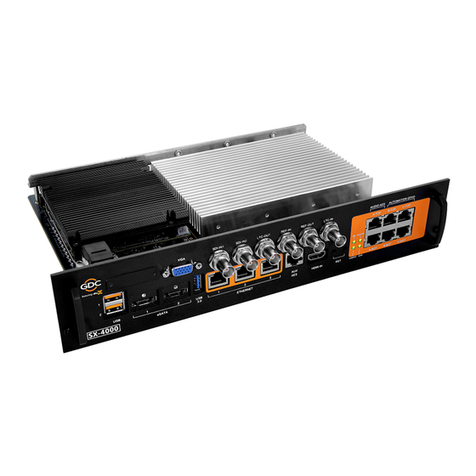
Figure 2 GDC Integrated Media Block with High Frame Rate (IMB HFR)
Note: If the projector comes with the GDC IMB pre-installed, the instructions in Section 3 can
be skipped.

SX-3000 Installation Manual
Page 5 of 43
3.1 Remove existing interface board/placeholders
from projector.
Before installing the IMB, check the figures below to ensure proper placement.
3.1.2 Barco Projector Placement
Figure 3 shows an interface board (with SMPTE 292 inputs) connected to a Barco projector. This
board must be removed in order to install the IMB.
Figure 3 IMB Placement on Barco projectors
3.1.3 Christie Projector Placement
Figure 4 shows the location where the IMB should be installed on a Christie projector. Remove
any existing interface boards or placeholder faceplates from this position before installing the
IMB.
Figure 4 IMB Placement on Christie projectors
Remove for
IMB
installation
IMB
installed
here

SX-3000 Installation Manual
Page 6 of 43
3.1.4 NEC Projector Placement
Figure 5 shows the location where the IMB should be installed on a NEC projector. Remove any
existing interface boards or placeholder faceplates from this position before installing the IMB.
Figure 5 IMB Placement on NEC projectors
Please refer to the projector manuals for more details on preparing the projector for IMB
installation.
3.2 Inserting the IMB into the projector
Please make sure the projector is powered off before installing the IMB on the projector.
Figure 6 Inserting the IMB into the projector
Insert the IMB as shown in Figure6.
The IMB should slide into the projector on the rails provided by the IMB slot, and the IMB
faceplate should be flush with the other existing faceplates once properly inserted.
3.2 Projector Network
Connect the provided Cat 5e LAN cable form the SX-3000 Ethernet 2 port to the projector’s
Ethernet port. Please see Section 8 for IP network instructions after the SX-3000 is installed.
IMB
installed
here

SX-3000 Installation Manual
Page 7 of 43
4External Monitor, Keyboard and Mouse
Before the server can be operated through VNC from the projector, you will first need to
connect an external monitor to the front VGA connection, and a keyboard and mouse to the
USB connection of the SX-3000 unit.
Note: when using an external touch screen for the first time. An external keyboard and mouse is
required before the touch screen is calibrated.
5The PSD-3000P External Hard Drive Unit
Each PSD-3000 unit is shipped with the content hard drives separate packaging. The server’s
content storage hard disks are inserted into the external hard drive bay. The content storage
hard disks must be inserted into the PSD-3000P and connected the SX-3000 before starting the
server.
5.1 Inserting the individual RAID drives into the bay
Ensure that the server is powered off before connecting the external content storage drive. Only
3of the 4 hard drive bays will be used in the PSD-3000P. The 4th drive bay can be used as a spare.
To insert the drives into the PSD-3000P:
1Use the included keys to open the long main silver door covering the hard drive bays.
Four hard drive bay doors will be exposed.
2On each bay, unlock the triangle shaped lock to open the gray and black lid of each
content storage drive. Then lift up the grey handle on the front of the drive bay.
Figure 7 Inserting the Drives into the PDS-3000M
3Insert each drive into the separate bay of the unit. Figure 7
Note: Each hard drive can be inserted into any drive slot from 1-3. They do not need
to be placed in any particular order.
4Once the content storage drives has been inserted, close the grey handle by push in
toward the HDD until it clicks. Then lock in the content storage drive.
5Close and lock the door covering the hard drive bay.

SX-3000 Installation Manual
Page 8 of 43
Figure 8 Hard Drive bays 1-3 of the PSD-3000P
5.2 Connecting the PSD-3000P drive bay to the SX-3000
Note: On the bay PSD-3000P unit there are 4 hard drive bays and 4 SATA connectors. The unit
only utilizes 3 of the 4 bays. The 4th bay and port is to be used as a back-up if needed. The Hard
drive bay (Figure 6) corresponds with the SATA port (Figure 9) on the back of the unit.
To connect the PSD-3000P to the SX-3000, please use the following instructions.
1. Connect SATA ports 1, 2, and 3 on the back of the PSD-3000 to the eSATA ports
on the SX-3000. There is no particular order these connections.
Figure 9 SATA ports of the PSD-3000P Figure 10 eSATA ports of the SX-3000
2. Plug in the 5V power supply and connect to the back of the PSD-3000P.
Figure 11 PSD–3000M Power Supply plug and Power Switch
3. Power on the unit with the switch next to the power plug. (Figure 11). Then
power on the projector with SX-3000 before moving on to the next steps.
Important Note: Always power on the PSD-3000P external hard drive bay before powering up
the projector.

SX-3000 Installation Manual
Page 9 of 43
6The PSD-3000U External Hard Drive Unit
The PSD -3000U hard drive unit features 3 bays. Each PSD-3000U unit is shipped with the
content hard drives separate packaging. The server’s content storage hard disks are inserted
into the external hard drive bay. The content storage hard disks must be inserted into the PSD-
3000U and connected the SX-3000 before starting the server.
6.2 Inserting the individual RAID drives into the bay
Ensure that the server is powered off before connecting the external content storage drive.
Figure 12 Inserting the Drives into the PDS-3000U
To insert the drives into the PSD-3000U in each individual bay:
6Open the hard drive bay by pushing in the
7Insert the hard drive in to the bay and push in.
8Push close the handle until it clicks to lock in the drive.
9Insert each drive into the separate bay of the unit. Figure 7
Note: Each hard drive can be inserted into any drive slot from 1-3. They do not need
to be placed in any particular order.
10 Once the content storage drives has been inserted, and the door is closed in. You can
lock the door by using the plastic key (Figure 8) to push the tab on the front of each
door up. Exposing a red color (Figure 9)
Figure 13 Hard Drive Key Figure 14 Door Lock

SX-3000 Installation Manual
Page 10 of 43
6.3 Connecting the PSD-3000U drive bay to the SX-3000
Note: On the bay PSD-3000U unit there are 3 hard drive bays and 3 SATA connectors. The Hard
drive bay front number corresponds with the SATA port (Figure 15) on the back of the unit.
To connect the PSD-3000U to the SX-3000, please use the following instructions.
1. Connect SATA ports 1, 2, and 3 on the back of the PSD-3000U to the eSATA
ports 1-3 on the SX-3000.
Figure 15 SATA ports of the PSD-3000U Figure 16 eSATA ports of the SX-3000
2. Plug in the power supply and connect to the back of the PSD-3000M.
Figure 17 PSD–3000M Power Supply Plug Figure 18 PSD–3000M Power Supply Plug
4. Power on the unit with the switch in the front left. (Figure 18). Then power on
the projector with SX-3000 before moving on to the next steps.
Important Note: Always power on the PSD-3000U external hard drive bay before powering up
the projector.

SX-3000 Installation Manual
Page 11 of 43
7Operation with PSD-3000U/P
7.1 Importing the RAID Array
Once the PSD-3000U/P RAID set is connected to the SX-3000 IMB properly the RAID array will
have to be imported in the system. This is done through the Admin panel of the software.
To import the RAID array from the PSD-3000U/P storage unit, please use the following steps:
1. From the Control Panel click on the [Admin Panel]
2. Click [Focus] at the far bottom right of the keyboard, then click the cursor in the
“Password” text box to enter the password configos
3. Select [Storage System Management] (1)
4. Select [Import RAID array] (2)
Figure 19 Storage System Management Screen
5. A pop-up window will appear to confirm importing the RAID, select [Yes]
Figure 20 Import RAID Confirmation
6. Please reboot the server after selecting [Yes] for this to take effect.
1
2

SX-3000 Installation Manual
Page 12 of 43
7.2 Selecting the PSD-3000U/P as a Content source
After the RAID is imported, you will need to define the PSD-3000P/U as the content source.
Using the steps below:
1. In the SMS window select the [Configuration] button, and enter the password for the
configuration menu under the maintenance access.
2. Select the IMB Storage tab
3. Click on the option use [Use eSATA RAID (x3)]. The RAID will be re-mounted.
Figure 21 IMB Storage page

SX-3000 Installation Manual
Page 13 of 43
8SX-3000 IP Setup
The IP address of the SOM and the IMB will need to be set for proper operation. The SOM and
the IMB IP are to be on the same subnet.
8.1 IMB Network Setup
To edit the IP addresses of the Ethernet ports, use the following instructions:
1Enter the SMS screen.
2Click [Configuration] to access the Configuration page.
3Select Maintenance access from the top drop down menu. Enter the number password
and select [OK]
4Select the IMB Network tab
5Enter the Subnet Mask. As well as the desired IMB IP and SOM IP addresses.
Figure 22 IMB Network settings screen
6Once the settings have been entered, click on [Validate IPs].

SX-3000 Installation Manual
Page 14 of 43
7If all of the IP addresses are valid, you will get the following pop-screen:
Figure 23 IPs are Valid Confirmation
8Click [OK] to exit.
8.2 Projector Connection
The Ethernet 2 connection and the projector are to be on the same subnet. Since the SX-3000 is
connected directly to the Projector, there is no need to set the IP address for the server to the
projector. The option to set the IP for the projector will be inactive.
Figure 24 CineCanvas Page

SX-3000 Installation Manual
Page 15 of 43
8.3 IMB Marriage and Clearing Door Tampers from
the SX-3000
Please use the following steps below to perform the marriage between the SX-3000 and to clear
the door tampers on the SX-3000:
1Enter the SMS screen.
2Click [Configuration] to access the Configuration page.
3Select Maintenance access from the top drop down menu. Enter the number password
and select [OK]
4Select the General tab
5Click [IMB] to access the Configuration page.
Figure 25 Configuration Menu - General Page
7. A dialogue box will appear to warn you that remote management will be
disabled to continue. Click [Yes].
Figure 26 Remote Management Disable Warning

SX-3000 Installation Manual
Page 16 of 43
8. The following box will appear:
Figure 27 IMB Status
9. Click [Marry] to perform the marriage of the projector and IMB.
10. Click [Close] to clear the door tamper errors with the projector.
11. After the Marriage is preformed and the tampers are clear, click [OK] to exit this
screen.
12. After you select OK a dialogue box will appear asking if you would like to enable
the remote connection. Click [Yes].
Figure 28 Enable Remote Management

SX-3000 Installation Manual
Page 17 of 43
9Series 2 projector setup
To work with the GDC IMB, the projector must be set up according to the requirements of the
projector manufacturer. It is required to use a VGA monitor and USB keyboard and mouse
connected to the IMB in order to setup the connection between the IMB and the projector.
Once the connection is complete the monitor, keyboard, and mouse can be removed and the
SMS can be accessed via VNC from the TMS or projector.
9.1 Barco Series 2 Projector Setup
No system configuration is required for Barco Series 2 projector to work with the GDC IMB. The
Service Door/Marriage Tamper on the server must be cleared before the IMB can be used for
playback.
In order to use the IMB for content playback, the INPUT source of the projector macros must be
set to IMB.
Figure 29 INPUT source settings on Barco Series 2 projector

SX-3000 Installation Manual
Page 18 of 43
9.2 NEC Series 2 Projector
In order to configure an NEC Series 2 projector to work with IMB, the following steps must be
taken:
1. Switch on the projector so that it is in STANDBY mode.
2. Use the Digital Cinema Communicator for S2 Windows software provided by NEC to
connect to the projector.
3. Select [Start] [Mode] [Service] and enter the Service password to activate
service mode operation. (Shown below)
Figure 30 Service Mode on NEC Digital Cinema Communicator
4. Select [Setup] [Option Slot] on the Digital Cinema Communicator and select IMB
for Slot B in Option Slot Setting. (Shown on the next page)

SX-3000 Installation Manual
Page 19 of 43
Figure 31 Option slot settings on NEC Digital Cinema Communicator
5. Select [Start] [Power] [On] to power on the projector.
6. Clear the Service Door/Marriage Tamper on the server (refer to Section 6.3 / Page
13).
In order to use the IMB for content playback, the INPUT source of the projector macros must be
set to IMB.
Other manuals for SX-3000
4
Table of contents
Other GDC Server manuals

GDC
GDC SR-1000 STANDALONE INTEGRATED MEDIA BLOCK User manual

GDC
GDC SX-2001A SERIES User manual

GDC
GDC SX-2001A SERIES User manual

GDC
GDC SX-2000A Series User manual

GDC
GDC Standalone IMB SR-1000 User manual

GDC
GDC Standalone IMB SX-4000 User manual

GDC
GDC SR-1000 STANDALONE INTEGRATED MEDIA BLOCK User manual

GDC
GDC SX-2000ATO User manual

GDC
GDC SX-2000 User manual