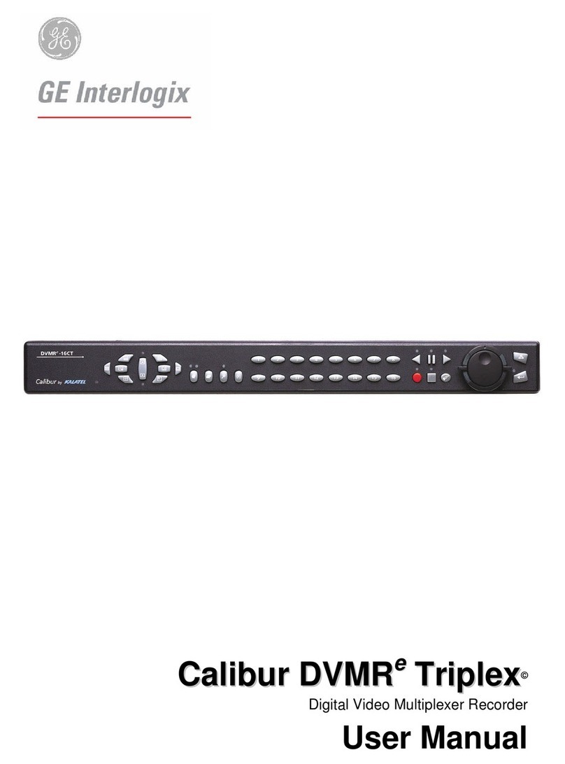
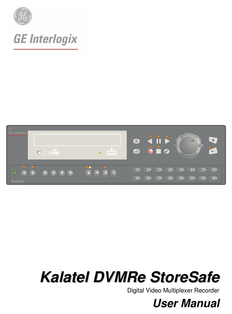
GE Interlogix DVMRe Triplex User manual

0150_0269A.pmd 6/18/2003, 6:28 PM1

1 | Introduction
Welcome to the DVMRe Triplex QuickStart Guide. This guide helps
you set up and use your DVMRe. It includes step-by-step instructions
and helpful illustrations that show you how to connect the compo-
nents of a surveillance system, program basic recording functions,
and view live and recorded video images.
The QuickStart Guide is for basic setup and operation. For
advanced functions, you can find more detailed information in the
User Manual.
Introduction
TIP:
You’ll find special items like Tips and
Cautions in the page margins. These
items make setup and basic operation
easier.
Kalatel DVMRe Triplex
Information in this document is subject to
change without notice.
©2003 GE Interlogix. All rights reserved.
TIP:
If you have a problem setting up or
operating your DVMRe, try these
solutions, in this order:
1)Re-read the QuickStart Guide
2)Read the corresponding section of the
User Manual
3)Call Technical Support
From 6 A.M. to 5 P.M. (Pacific time)
If calling from outside the United States:
011-1-541-754-9134
If calling from within the United States:
800-469-1676
From 5 P.M. to 6 A.M. (Pacific time)
541-740-3589
0150_0269A.pmd 6/18/2003, 6:28 PM2

2 | DVMRe Package Contents
DVMRe Package Contents
CAUTION:
Power – You must use a stable power source
that falls within the rated voltage of the
12 VDC power supply. If your power source
might experience surges or dips, use an
uninterruptable power supply (UPS).
The following items are used for basic setup and operation. Items not shown here are for
advanced functions—refer to the User Manual for information on these items.
Additional system components
A basic surveillance system also includes a monitor, one or more cameras, and connection cables.
Kalatel DVMRe Triplex
DVMRe
QuickStart Guide
User Manual
Universal
power supply
Power
cord
Surveillance monitor Coaxial cable Surveillance camera
CAUTION:
Installation Area – Your DVMRe needs
space around it for ventilation. Make sure
the fans and vents on the sides of the unit
are not obstructed. Install your DVMRe in a
place where the temperature is always
between 0 and 40 °C (32 and 104 °F) and
has normal humidity (between 10% and
80%). Don’t install the DVMRe on top of a
hot piece of equipment, and always leave
space between rack-mounted equipment.
Don’t install the DVMRe near a water
source or anywhere that it will be exposed
to rain or moisture.
CAUTION:
Stacking Equipment – You can place other
equipment on top of the DVMRe, but only
if it weighs less than 35 pounds (16 kg).
0150_0269A.pmd 6/18/2003, 6:28 PM3
3 | Connecting and Powering Up
Power connection
Composite monitor A output
Camera inputs
SVHS monitor A output
ConnectingandPoweringUp
DVMRe back panel
Camera back panel Video outputPower connection
Monitor back panel Video inputPower connection
0150_0269A.pmd 6/18/2003, 6:28 PM4

4 | Connecting and Powering Up
TIP:
Connection – Depending on the model,
you can connect as many as 4, 10, or 16
cameras to your DVMRe. Follow the same
instructions for each additional camera.
TIP:
Connection – You can connect to either
of the camera inputs for each camera.
The second input can be used to send
the camera signal to other devices if
necessary.
TIP:
Connection – You may
also use coaxial cable
with your DVMRe, but
not at the same time
as SVHS cable.
Start by connecting your DVMRe to the monitor and camera(s).
ConnectingandPoweringUp
1Connect the coaxial camera cable to
the video output on the camera. 2Connect the coaxial camera cable to the top
Camera 1 input on the DVMRe.
4Connect the SVHS monitor cable to
the video input on the monitor.
3Connect the SVHS monitor cable to the
monitor A output on the DVMRe. (See
TIP at right if using coaxial cable.)
TIP:
Connection – To connect additional
components such as keypads or network
connections, see the User Manual.
0150_0269A.pmd 6/18/2003, 6:28 PM5

5 | Connecting and Powering Up
CAUTION:
Powering Up – For European electrical
systems, use the 220 V power cord
included with your DVMRe. Make sure
other components such as cameras and
monitors have the proper electrical plugs
as well.
To power up your system, you need an electrical outlet for the DVMRe, one for the monitor, and
one for each connected camera. Power up your system in the following order:
CAUTION:
Signal Loss – If a camera is improperly
connected to the DVMRe, the monitor
shows a Signal Loss message. Check the
connection and reconnect the camera if
necessary.
ConnectingandPoweringUp
1Plug the monitor and camera power cords
into the outlets.
TIP:
Powering Up – When you plug the
DVMRe power supply into an outlet, the
DVMRe automatically detects all con-
nected cameras. The DVMRe shows which
version of software is installed, then shows
a display of live views from each con-
nected camera and automatically begins
recording.
2Plug the single-prong end of the DVMRe
power cord into the power connection on
back of the DVMRe.
3Plug the other end of the DVMRe power
cord into the outlet on the DVMRe power
supply.
4Plug the DVMRe power supply cord into the
outlet.
0150_0269A.pmd 6/18/2003, 6:28 PM6

6 | System Controls
Kalatel DVMRe Triplex
SystemControls
Here are the functions of each of the controls
on the front of the DVMRe. (Multiscreen
viewing options vary by model.)
Camera selection
6-way
view
Alarm
Zoom Record
Stop
Search Enter
Jog/Shuttle
PIP
view
4-way
view
7-way
view
16-way
view
10-way
view Monitor A
9-way
view
13-way
view
Sequence Function
Reverse Play
Pause/Freeze
Forward Play Menu
Monitor B
0150_0269A.pmd 6/18/2003, 6:28 PM7

7 | System Controls
SystemControls
Using Jog, Shuttle, Menu, and Enter
To navigate the menus and program your DVMRe, use the Menu and Enter buttons and the Jog/Shuttle.
The Jog is the inner dial. Use it to select menu
items and some settings. To operate it, place
your finger in the round indentation and
rotate it in either direction.
The Shuttle is the outside ring. Use it to move
between menus and select some settings. To
operate it, twist it in either direction, gripping
the knobs on either side.
The Menu button brings up the Main menu
and enables you to move from submenus back
to the Main menu.
The Enter button brings up
submenus and confirms settings.
Main QuickInstall Operator SystemView
Time/Date
Sequencing
Record
Alarms
Macro
Motion Detection
Camera Setup
Archive Setup
Audio Setup
Communications
Front Panel Lock
Factory Settings
Passwords
English
French
German
Shuttle
Jog
Enter
0150_0269A.pmd 6/18/2003, 6:28 PM8

8 | Initial Setup
1Press the Menu button.
InitialSetup
Factory Defaults
Before you program your DVMRe, return all
settings to the factory defaults. To do this:
1Jog in the Main menu to Factory Settings
and press Enter.
2 Enter the Factory Default password: for
4-camera models, 4111; for 10- and
16-camera models, 8111.
The DVMRe reboots, reverting all settings
except time, date and IP address to factory
defaults. The DVMRe beeps when resetting is
complete.
To access the Main menu and begin setup, follow these steps:
MainQuickInstallOperatorSystemView
PasswordBox
EnteranewPassword
----
2Enter the installer password by using the
number buttons.
For 4-camera models, enter 3444.
For 10- and 16-camera models, enter 3477.
3The Main menu is the first menu you see.
High
Event and TL
02
Continuous
Enabled
Active
5
None
Yes
Camera 01, Camera 02, etc.
50%
Enabled
57600 Baud
19200 Baud
Network address 001
Enabled
Disabled
Record Quality:
Event Settings:
Pre Event Duration:
Record Mode:
Motion Detection:
setup parameters:
sensitivity:
relay output:
link to event:
Camera Titles:
Camera AGC:
Cameras:
RS232 Port 1:
RS232 Port 2:
RS485:
Ethernet:
POTS:
Settings
0150_0269A.pmd 6/18/2003, 6:28 PM9

9 | Initial Setup
Custom Passwords
The DVMRe comes with preset Installer and
Operator passwords. The Installer password
gives access to all menu functions. The
Operator password gives access to only the
Operator and SystemView menus.
To change the preset passwords:
1 Jog to Passwords in the Main menu and
press Enter.
2 Jog to the password you wish to change and
press Enter.
3Use the number buttons to enter a new
password and then jog to OK and press
Enter.
4 Reenter the password, jog to OK, and press
Enter.
5Press Menu to exit.
Choose a Language
For a language other than English:
1Jog to Factory Settings and press Enter.
2For 4-camera models, enter 1414 and press
Enter. For 10- and 16-camera models, enter
5415 and press Enter.
3Jog to select a language and press Enter.
InitialSetup
CAUTION:
Password – Once you set custom pass-
words, you cannot revert to the default
passwords. If you forget your password, you
must send the DVMRe back to the factory
to be reset.
MainQuickInstallOperatorSystemView
Time/Date
Sequencing
Record
Alarms
Macro
MotionDetection
CameraSetup
ArchiveSetup
AudioSetup
Communications
FrontPanelLock
FactorySettings
PasswordsEnglish
French
German
MainQuickInstallOperatorSystemView
Time/Date
Sequencing
Record
Alarms
Macro
MotionDetection
CameraSetup
ArchiveSetup
AudioSetup
Communications
FrontPanelLock
FactorySettings
PasswordsInstallerPassword
OperatorPassword
EthernetPassword
PasswordBox
EnteranewPassword
----
0150_0269A.pmd 6/18/2003, 6:28 PM10

10 | Initial Setup
Camera Titles
To change the title that shows on the monitor
for each camera:
1Jog to Camera Setup in the Main menu and
press Enter. Camera Titles is highlighted;
press Enter.
2Jog to Edit Titles and press Enter. Camera 1
and its title shows.
3Press Enter again to highlight the title for
Camera 1, and the character bank appears in
the middle of the screen.
4To change the first letter of the title, jog to
the character you want and press the
number 2 button. Repeat for each new
letter, using the number 1 button for blank
spaces.
5For additional cameras, use the shuttle to
select a camera number.
6When you’re done, press Enter, jog to OK,
and press Enter again. Press Menu twice to
exit to the Main menu.
InitialSetup
TIP:
Time Setup – You can change to a 12-hour
time format that indicates a.m. and p.m.,
but only after you’ve set the time and date
as described at left. Follow the same steps
for setting the time format, but now select
12-hour time.
Time and Date
To set the time format:
1Jog to Time/Date and press Enter.
2Jog to Set Time Format and press Enter.
3Jog to select 24-hour time and press Enter.
Press Menu to exit.
To set the time:
1Jog to Set Time and press Enter.
2Press Enter again to move to hours and jog
to select the hour, using 24-hour time
format. (See TIP at right to change to
12-hour time later.)
3Shuttle to move to minutes and jog to
select. Do the same for seconds.
4Press Enter when you’re done, and then jog
to OK and press Enter. Press Menu to exit.
To set the date, use the same process as for
time.
TIP:
Date Setup – The DVMRe automatically
selects the day of the week based on the
date you enter.
Main QuickInstall Operator SystemView
Time/Date
Sequencing
Record
Alarms
Macro
Motion Detection
Camera Setup
Archive Setup
Audio Setup
Communications
Front Panel Lock
Factory Settings
Passwords
Time / Date Display
Set Time Format
Set Da
Set Ti
Set Da
Set Ma
Set Re
Time Format Setup
Select Format
12HOUR
MainQuickInstallOperatorSystemView
Time/Date
Sequencing
Record
Alarms
Macro
MotionDetection
CameraSetup
ArchiveSetup
AudioSetup
Communications
FrontPanelLock
FactorySettings
Passwords
CameraTitleEdit
[CANCEL][OK]
Camera1
Title:Frontroom
@ABCDEFGHIJKLMNOPQRSTUVWXYZ[\]^_
SEQkeyselectscharacterbank
'1'Keyinsertsblankcharacter
'2'Keyinsertsselectedcharacter
Daylight-saving Time
To adjust for daylight-saving time:
1Jog to Time/Date and press Enter.
2Jog to Set Region and press Enter.
3Select your region and time zone.
EST equals GMT minus 05:00
CST equals GMT minus 06:00
MST equals GMT minus 07:00
PST equals GMT minus 08:00
0150_0269A.pmd 6/18/2003, 6:28 PM11

11 | Recording Settings
Record Speed
To set the record speed for each camera:
1 Jog to Record in the Main menu and press
Enter.
2Jog to Timelapse Record Rate and press
Enter. Camera 01 is highlighted.
In this screen you choose the record rate for
all connected cameras. The maximum rate
for one or two cameras is 30 pictures per
second (pps) each. For three or more
cameras, the maximum rate is 48 pps, divided
among all cameras. The recording capacity of
your DVMRe shows at the bottom right of
the screen—it will change based on the
record speeds you select.
3Jog to select a rate for Camera 01, shuttle to
the next camera, and jog to select a rate for
it.
4Continue for all cameras and then jog to OK
and press Enter.
Record Quality
To set the record quality for each camera:
1 Jog to Record in the Main menu and press
Enter.
2Jog to Record Quality and press Enter. The
record quality level for Camera 01 is
highlighted.
3Shuttle to change the level, and jog to
additional cameras.
4When the settings are the way you want
them, jog to OK and press Enter.
RecordingSettings
Event Settings
To set the type of recording for each camera:
1 Jog to Record in the Main menu and press
Enter.
2Jog to Event Settings and press Enter.
Camera 01 is highlighted.
3Jog to Type and shuttle to change to TL
(time-lapse). This means cameras will record
at the same speed at all times.
4Jog back to Camera and shuttle to Camera
02. Change all connected cameras to TL
using these steps.
5When done, jog to OK and press Enter.
TIP:
Record Lock – To prevent anyone else
from changing record settings, jog to
Record Lock and press Enter. Jog to On
and press Enter. This means the installer
password is necessary to stop recording or to
change settings.
MainQuickInstallOperatorSystemView
Time/Date
Sequencing
Record
Alarms
Macro
MotionDetection
CameraSetup
ArchiveSetup
AudioSetup
Communications
FrontPanelLock
FactorySettings
Passwords
RecordQuality
[CANCEL][OK]
Camera01:--------
Camera02:--------
Camera03:--------
Camera04:--------
Camera05:--------
Camera06:--------
Camera07:--------
Camera08:--------
Camera09:--------
Camera10:--------
Camera11:--------
Camera12:--------
Camera13:--------
Camera14:--------
Camera15:--------
Camera16:--------
147days10h(TL)
147days10h(Total)
MainQuickInstallOperatorSystemView
Time/Date
Sequencing
Record
Alarms
Macro
MotionDetection
CameraSetup
ArchiveSetup
AudioSetup
Communications
FrontPanelLock
FactorySettings
Passwords
RecordT
RecordQ
EventSe
Timelaps
EventRe
Activity
AlarmRe
RecordM
DiskMai
RecordL
AutoDel
RecordQuality
[CANCEL][OK]
Camera01:High
Camera02:High
Camera03:High
Camera04:High
Camera05:High
Camera06:High
Camera07:High
Camera08:High
Camera09:High
Camera10:High
Camera11:High
Camera12:High
Camera13:High
Camera14:High
Camera15:High
Camera16:High
MainQuickInstallOperatorSystemView
Time/Date
Sequencing
Record
Alarms
Macro
MotionDetection
CameraSetup
ArchiveSetup
AudioSetup
Communications
FrontPanelLock
FactorySettings
Passwords
EventCameraSettings
Camera
:1
Type:EVENT+TL
PreEventDuration:02
PostEventDuration:000
EventAssociatedCameras:------
[CANCEL][OK]
0150_0269A.pmd 6/18/2003, 6:28 PM12

12 | Live Viewing Options
Multiscreen Views
Press any Multiscreen button. The monitor
displays views beginning with Camera 1 up to
the total number of cameras chosen.
LiveViewingOptions
This section shows you basic live and playback viewing options and how to conduct a basic search
for video images. For advanced operation, see the User Manual.
Full-Screen View
Press any number button to view a full-screen
display of that camera.
Zoom
While viewing a full-screen display, press the
Zoom button for a 2X view. You can use the
Jog and Shuttle to move within the zoomed
view. (Note: The camera does not move.) Press
Zoom again to cancel.
Freeze
Press the Freeze button to freeze all camera
views being displayed. Press Freeze again to
return to a live view.
TIP:
Viewing Options – By pressing any number
button twice the monitor displays the
status display box. By pressing three times
the monitor displays associated ATM or
ASCII text.
0150_0269A.pmd 6/18/2003, 6:28 PM13

13 | Playback Options
PlaybackOptions
Fast Forward
During forward or reverse playback, turn the
Shuttle clockwise to speed up playback. The
further you turn the Shuttle, the faster the
images play back.
Fast Reverse
During forward or reverse playback, turn the
Shuttle counterclockwise for fast reverse
playback. The further you turn the Shuttle,
the faster the images play back.
Reverse Play
Press the Reverse Play button. The monitor
displays images at the rate they were recorded.
Press Stop to end reverse play, or press Forward
Play to return to forward play.
Multiscreen Playback
Press any of the Multiscreen display buttons to
activate a multiscreen display.
Forward Play
Press the Forward Play button. Playback is
available only on monitor A. Press Forward Play
twice and select a multiscreen view to allow
both live and playback options on the same
monitor. The monitor displays images from the
beginning of the most recent recorded video,
at the rate they were recorded. Press Stop to
end playback.
Here is a sample of the 6-way view:
0150_0269A.pmd 6/18/2003, 6:28 PM14

14 | Playback Options
Full-Screen Playback
Press any camera number button for a full-
screen playback of that camera.
PlaybackOptions
Zoom
Select the full-screen display for any camera
and then press Zoom for a 2X view. You can
use the Jog and Shuttle to move within the
zoomed view. (Note: The camera does not
move.) Press Zoom again to cancel.
Freeze
Press the Freeze button to freeze all camera
views being displayed. Press Freeze again to
cancel.
Frame Advance
During Freeze mode, jog to view frames
individually in either direction.
Stop
Press Stop to end playback and return to live
viewing.
0150_0269A.pmd 6/18/2003, 6:28 PM15

15 | Searching Recorded Video
SearchingRecordedVideo
TIP:
Time and Date Display – Above and to the
right of the Disk Analysis screen is a date
and time window that shows the current
date and time.
TIP:
Detail Level – Shuttle expands the display
for more detail. The level of detail shows
at the bottom right of the graph. Level 1
is the least detail, Level 4 the most.
TIP:
Disk Analysis – To exit the Disk Analysis
screen without viewing recorded video,
press Menu.
To search for recorded video:
1Press Search. The Disk Analysis screen
appears on the monitor.
This screen shows the recording pattern for
each camera, by color. The graph shows a
bar for each camera, going left to right from
oldest recordings to newest. At the left of
the graph, at both the top and bottom, are
small cursors. In the top right corner of the
graph is a time and date display. The time
and date correspond to the cursor position.
2Jog to move the cursors left and right along
the bars; the time and date change to tell
you when each section was recorded.
3When you find a section you wish to view,
press Enter and the video begins to play,
starting from the date and time shown.
Select a full-screen (press a camera number)
or multiscreen view (choose a Multiscreen
button), depending on what you want to see.
While the video is playing, you are in
playback mode and can use any of the
functions described in Playback Options.
4Press Stop to return to live viewing.
Disk Analysis Screen
Alarm Event Activity Videoloss Present Absent
Hit SEARCH again to enter Advanced Search Level 1
1
2
3
4
5
6
7
8
9
10
11
12
13
14
15
16
01/21/2002 20:17:0101/21/2002 20:17:01
Level 1
0150_0269A.pmd 6/18/2003, 6:28 PM16
Table of contents
Other GE Interlogix DVR manuals

GE Interlogix
GE Interlogix Digital Video Multiplexer Recorder User manual

GE Interlogix
GE Interlogix StoreSafe User manual

GE Interlogix
GE Interlogix Interlogix BusSecure User manual

GE Interlogix
GE Interlogix Kalatel 0150-0255C User manual

GE Interlogix
GE Interlogix Kalatel DVMRe Matrix User manual

GE Interlogix
GE Interlogix Kalatel VDR User manual

GE Interlogix
GE Interlogix DVMRe User manual

GE Interlogix
GE Interlogix TRIPLEX 0150-0193C User manual