GE JP3030*J series How to use

GE Appliances
General Electric Company
Louisville, Kentucky 40225 31-9247
2015 Electric Radiant and Induction
Cooktops
Technical Service Guide
November 2015
GE Appliances
36” Radiant
Cooktops
JP3536_J
JP5036_J
PP7036_J
PP9036_J
CP9536_J
ZEU36R_J
30” Radiant
Cooktops
JP3030_J
JP3530_J
JP5030_J
PP7030_J
PP9030_J
CP9530_J
ZEU30R_J
30” Induction
Cooktops
PHP9030_J
CHP9530_J
ZHU30R_J
36” Induction
Cooktops
PHP9036_J
CHP9536_J
ZHU36R_J

– 2 –
IMPORTANT SAFETY NOTICE
The information in this service guide is intended for use by
individuals possessing adequate backgrounds of electrical,
electronic, and mechanical experience. Any attempt to repair a
major appliance may result in personal injury and property
damage. The manufacturer or seller cannot be responsible for the
interpretation of this information, nor can it assume any liability in
connection with its use.
WARNING
To avoid personal injury, disconnect power before servicing
this product. If electrical power is required for diagnosis or test
purposes, disconnect the power immediately after performing the
necessary checks.
RECONNECT ALL GROUNDING DEVICES
If grounding wires, screws, straps, clips, nuts, or washers used to
complete a path to ground are removed for service, they must be
returned to their original position and properly fastened.
GE Appliances
Technical Service Guide
Copyright © 2015
All rights reserved. This service guide may not be reproduced in whole or in part
in any form without written permission from the General Electric Company.

– 3 –
Table of Contents
Safety Requirements.....................................................................................................................................................................4
Introduction.......................................................................................................................................................................................5
Nomenclature...................................................................................................................................................................................7
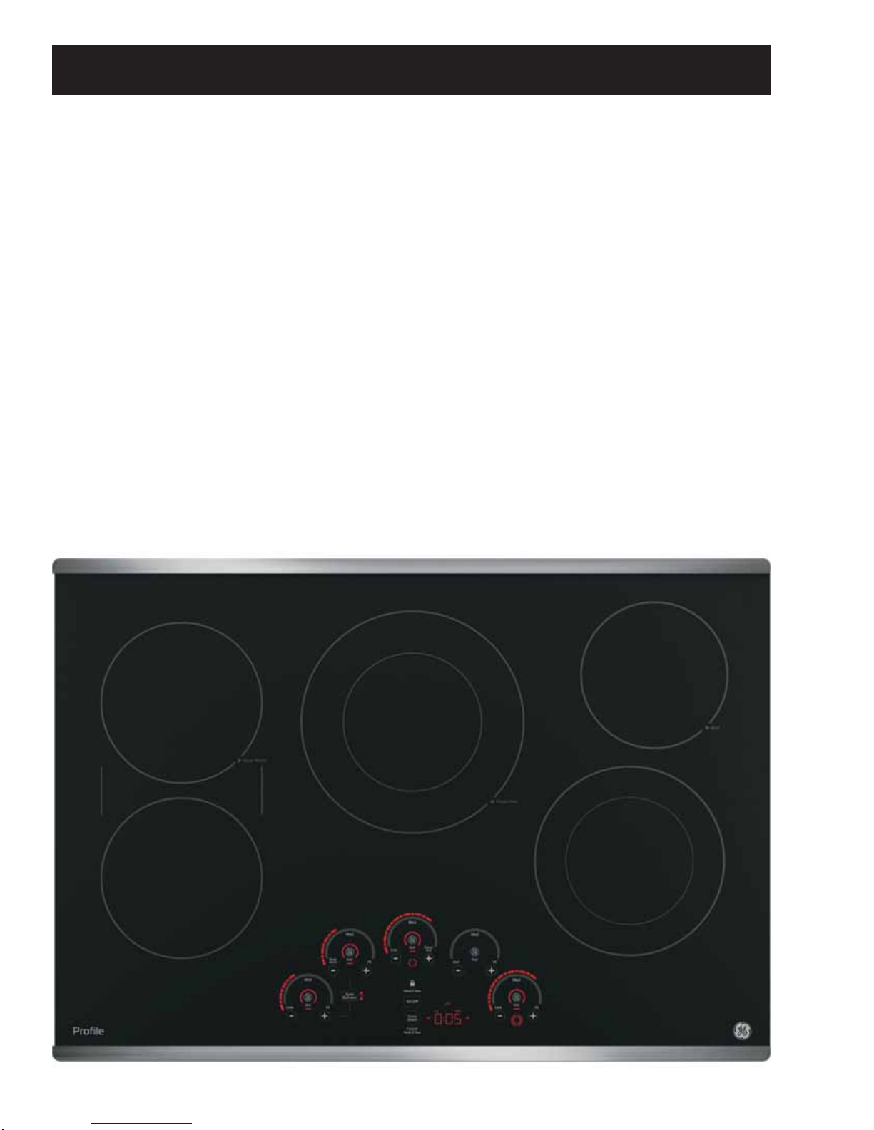
Electronic Control Radiant Cooktop Features....................................................................................................................8
Electronic Control Radiant Component Access................................................................................................................9
Wiring Diagram - Electronic Control............................................................................................................................12
Schematic - Electronic Control.......................................................................................................................................13
Troubleshooting Electronic Control Cooktop Elements.................................................................................................14
Service Notes: Electronic Control Cooktop..........................................................................................................................15
Accessing Electronic Control Cooktop Elements..............................................................................................................16
Service Mode for Electronic Control Cooktop....................................................................................................................18
Induction Cooktop Features.......................................................................................................................................................21
Normal Operating Sounds................................................................................................................................................23
PHP Model Features............................................................................................................................................................24
ZHU Model Features............................................................................................................................................................25
30” Induction Component View.....................................................................................................................................30
36” Induction Component View.....................................................................................................................................31
Induction Component Access...................................................................................................................................................32
Service Notes: Induction Cooktop...........................................................................................................................................34
Fault Codes..............................................................................................................................................................................36
Wiring Diagram.....................................................................................................................................................................37
,Q¿QLWH6ZLWFK5DGLDQW&RRNWRS)HDWXUHV ...........................................................................................................................38
,Q¿QLWH6ZLWFK&RPSRQHQW$FFHVV..........................................................................................................................................39
Radiant Element Access....................................................................................................................................................39
,Q¿QLWH6ZLWFK6FKHPDWLF..................................................................................................................................................42
,Q¿QLWH6ZLWFK:LULQJ'LDJUDP.......................................................................................................................................43
Accessories..............................................................................................................................................................................44
Index......................................................................................................................................................................................................45
Warranty.............................................................................................................................................................................................46

– 4 –
Prior to disassembly of the cooktop to access components, GE Factory
Service technicians are REQUIRED to follow the Lockout / Tagout
(LOTO) 6 Step Process:
Safety Requirements
GE Factory Service Employees are required to use safety glasses with side shields, safety gloves and
steel toe shoes for all repairs.
Steel Toed Work Boot Electrically Rated Glove and
Dyneema® Cut Resistant
Glove Keeper Dyneema®Cut Resistant
Glove
Plano Type Safety Glasses
Prescription Safety Glasses
Safety Glasses must be ANSI
Z87.1-2003 compliant
Brazing Glasses
Cut Resistant Sleeve(s)
Step 1
Plan and Prepare Step 4
Apply LOTO device and lock
Step 2
Shut down the appliance Step 5
Control (discharge) stored energy
Step 3
Isolate the appliance Step 6
“Try It” verify that the appliance is
locked out

– 5 –
Introduction
The 2015 Electric Cooktops have been totally redesigned. For service, this means the complete removal of
the cooktop from its installation for repairs.
New Consumer Features (on some models):
• Backlit knobs
• Multiple timers
• Sync burners control two 7 inch elements simultaneously to evenly heat large cookware or griddles
• Custom setting allows consumer options on sound levels, LED brightness and more
On Café and Monogram, an accessory kit is available for consumers that want to use “Sous Vide”* cooking.
The Precision Cooking Probe communicates with the control board via the Bluetooth module to maintain
proper temperature for Sous Vide cooling.
*French for "under vacuum“: Sous vide is a method of cooking in which food is sealed in an FDA approved
airtight plastic bag and then placed in a temperature regulated water bath. The food is cooked much longer
than traditional cooking times at temperatures much lower than normally used for cooking, typically around
125°F to 150°F for meat and even higher for vegetables. This cooking method will cook the food item evenly,
ensuring that the inside is properly cooked without overcooking the outside, and will retain moisture.
Precision Cooking Probe Bluetooth Module

– 6 –
Electronic controls have two types of keypads.
The “Slew” control has (+) and (-) pads with a single digit display for each element.
The “Horseshoe” control has (+) and (-) pads with a sweeping display for each element.
Introduction (continued)
“Slew” Control View
“Horseshoe” Control View

– 7 –
Nomenclature
The nomenclature breaks down and explains what the letters and numbers mean in the model number.
Serial Number
7KH¿UVWWZRFKDUDFWHUVRIWKHVHULDOQXPEHULGHQWLI\WKHPRQWKDQG\HDURIPDQXIDFWXUH7KHOHWWHU
designating the year repeats every 12 years.
Example: LA123456S = June, 2013
A – JAN
D – FEB
F – MAR
G – APR
H – MAY
L – JUN
M – JUL
R – AUG
S – SEP
T – OCT
V – NOV
Z – DEC
2024 – Z
2023 – V
2022 – T
2021 – S
2020 – R
2019 – M
2018 – L
2017 – H
2016 – G
2015 – F
2014 – D
2013 – A
The Model/Serial
tag is attached
to the bottom
outside of burner
box.
The Mini Manual
is located inside
the burner box.
Brand
A - GE Artistry™ Series**
P - GE Profile Series**
C - GE Café Series
J - GE
P G B 9 5 0 S E J 1 S S
Configuration
A - 24” Free-standing
B - 30” Free-standing
D - 30” Drop-in
K - Wall Oven - 27” Cabinet
M - 27” Drop-in
N - Hood (non vented)
P - Cooktop
S - Slide-in
R - Wall Oven - 24” Cabinet
T - Wall Oven - 30” Cabinet
V - Hood (vented)
X - Accessory Feature Package
Designates features.
The higher the number,
the more features.
Indicator for
Engineering and
Product Service Only
Model Year
Designator
Product Color
SS - Stainless
ES - Slate
SA - Silver
WW - White on white
or true white
CC - Bisque on bisque
or true bisque
BB - Black on black
BR - Brushed Aluminum
BS - Black w/stainless accents
WS - White w/stainless accents
G - Gas
H - Induction
2 - Dual Fuel
Electric - Omit this character
Oven Type
S - Standard
P - Self Clean
B - Telescopic Downdraft
D - Warming Drawer
0-9 - Extended feature
pack on select
self-clean models.
Model/Door Color
C - Bisque Glass
T - True White Glass
K - True Bisque Glass
S - Stainless with Gray
R - Stainless with Black
B - Black Glass (or simply
glass door)
W - White Glass
D - Color Matched
G - Silver
Ignition System (Gas models)
C - Cordless Batter Ignition
E - Electronic Pilotless Ignition

– 8 –
Electronic Control Radiant Cooktop Features
PP9030 Details Shown:
• Five radiant cooking elements
• Glide touch controls “Horseshoe”
• 9”/6” Power Boil 3100 watt element
• 8”/5” Dual 2200 watt element
• Sync Burners
• Controls two 7” elements simultaneously to evenly heat large cookware or griddle
• Multi-element Timer
• Individual timer for each element
• Control Lock capability
• Protects against unintended activation
• Custom settings
• Red LED display with black glass surface and stainless steel trim
• Hot surface indicator lights

– 9 –
Electronic Control Radiant Component Access
1. Disconnect power to the cooktop.
2. Carefully remove the cooktop from the installation, and lay the glass side down on a protected surface.
To Access the Power Supply Board
1. Remove four 1/4 in. hex head screws from the power supply cover.

– 10 –
To Access the Display Board
1. Disconnect the harness connectors.
2. Remove six 1/4 in. hex head screws and separate the board from the cooktop.
3. The display board has a small connector that mates with the board mounted to the glass. The board can
be removed without removing the complete cooktop bottom by accessing, as shown on the previous
page.

– 11 –
To Access the Relay Board
1. 5HPRYH¿YHLQKH[KHDGVFUHZVIURPWKHUHOD\ERDUGFRYHU
Relay Board

– 12 –
Wiring Diagram - Electronic Control

– 13 –
Schematic - Electronic Control

– 14 –
Troubleshooting Electronic Control Cooktop Elements
To check an element from the relay board, follow this example for the center element.
1. Disconnect power to the cooktop.
2. Carefully remove the cooktop from the installation and lay the glass side down on a protected surface.
3. 5HPRYH¿YHLQKH[KHDGVFUHZVIURPWKHUHOD\ERDUGFRYHU
4. Check the resistance from J501 pin 1 grey/black to J501 pin 3 grey. It should measure approximately 76
ohms.
5. To check the thermal limit switch from the relay board; check the resistance from J501 pin 1grey/black
to grey wire on K516 terminal. It should measure approximately 32 ohms.
Location of the test points on the relay board.

– 15 –
Service Notes: Electronic Control Cooktop
Hot surface indicators are part of the display board. The indicators get a signal from the main control board.
On these models, if the touch board needs to be replaced, the glass cooktop must be replaced. The touch
board and glass cooktop are a single assembly. The display board and its light guide may be removed from
the touch board and installed on the new assembly.

– 16 –
Accessing Electronic Control Cooktop Elements
1. Disconnect power to the cooktop.
2. Carefully remove the cooktop from the
installation and lay the glass side down on a
protected surface.
3. Remove the T20 screws from the perimeter.
4. Remove four 1/4 in. hex head screws from the
power supply cover.
5. Disconnect two harness connectors from the
power supply board and one from the RJ45
connector. Set the assembly aside.
6. 5HPRYH¿YHLQKH[KHDGVFUHZVIURPWKH
relay board cover.
7. Disconnect the three multi-pin connectors and
both sets of L1 and L2 wires.
8. Remove the bottom cover and feed the
harnesses through the grommet.
9. Remove the bottom cover and place back into
the installation opening.
10. Remove the insulation.
11. Remove four 1/4 in. hex head screws from the
insulation cover.
12. Note that spring clips secure elements onto
maintop glass and frame assembly.
Grommet

– 17 –
13. Large elements also have a bracket that secures
with one 1/4 in. screw.

– 18 – (Continued next page)
Service Mode for Electronic Control Cooktop
Service Mode
Service Mode can be entered by the following steps:
1. Press and hold the front right burner ON/OFF key for 7 seconds until the tone is heard and "1" appears on
the timer.
2. Press and hold the rear right burner ON/OFF key for 7 seconds until the tone is heard and the software
version appears on the timer.
The following table provides the diagnostic features associated with each key.
DIAGNOSTIC MODE SUMMARY
Key Response
Left Rear + Displays fault codes on the Timer. Pressing this key multiple times will cycle
through each fault code until dashes appear showing the end of the codes. If no
active faults exist, only dashes will be shown with each press.
$OO2ȹ Pressing and holding for 5 seconds will clear the Fault Code that is currently
displayed.
Left Front + Turns on all the LEDs for 5 seconds.
Left Front - Exit Service Mode.
Right Front - Display main board software version.
Right Front + Display Induction board #1 software version.
Right Rear - Display Induction board #2 software version.
Right Rear + Display Induction board #3 software version (On 30 in. cooktop, this key is not
valid).
Timer Select
(or Timer ON/OFF)
ONLY use this when a mistake has been made in setting the model number for a
service replacement board.
To clear the service model number, press and hold for 7 seconds. Control will show
SEt in timer block, ready to reprogram the service control's model number.

– 19 –
Fault Codes for Electronic Control Cooktop
FAULT CODES
“x” in above chart represents a number 0-9. The number represents a failed component on the board .
User Interface
Fault Code Issue Description Possible Fixes
F1x UL "On" Indicator Light/LED failure Replace Display Board (under
Touch Board)
F7x User Interface (UI) Button Matrix
Error Replace Touch Board
F82 User Interface (UI) Microprocessor
Error Replace Display Board (under
Touch Board)
Machine Control (MC)
Fault Code Issue Description Possible Fixes
F6x UI cannot communicate with
Machine Control Check wires connecting UI to MC.
Replace Machine Control. Replace
Display Board (under Touch
Board).
F81 Machine Control (MC)
Microprocessor Error Replace Machine Control

– 20 –
SEt - SETTING UP UI SERVICE REPLACEMENT CONTROLS
Service Replacement UI's must be set up with the appropriate model number code to function correctly.
1. After replacing the control, power up the unit.
2. Upon power up, the UI will display the letters SEt after a few seconds. (On the GE UI units, all the LED's
PD\WXUQRQ¿UVWIRUXSWRVHFRQGVEHIRUHSEt appears on display.)
3. Using the Timer up "^" and down "v" keys, select the correct model number based on the table below.
4. Press and hold theTimer Select (or Time Start on models where this key is available) for 7 seconds to
store the model code in the control.
5. The control will restart and operate normally.
Model # Code Description
CHP9530xxxx AA1 30" Induction Café Blue
ZHU30Rxxxx AF1 30" Induction Mgm White
CHP9536xxxx AA2 36" Induction Café Blue
ZHU36Rxxxx AF2 36" Induction Mgm Blue
PP9030xxxx AC1 5DGLDQW3UR¿OH5HG
ZEU30Rxxxx AE1 30" Radiant Mgm White&Red
PP9036xxxx AC2 5DGLDQW3UR¿OH5HG
ZEU36Rxxxx AE2 36" Radiant Mgm White&Red
"Horseshoe" User Interface
Model # Code Description
PHP9030xxxx C1 30" ,QGXFWLRQ3UR¿OH
PHP9036xxxx C2 36" ,QGXFWLRQ3UR¿OH
JP5030xxxx A1 30" Radiant GE
JP5036xxxx A2 36" Radiant GE
"Slew" User Interface
This manual suits for next models
18
Table of contents
Other GE Cooktop manuals