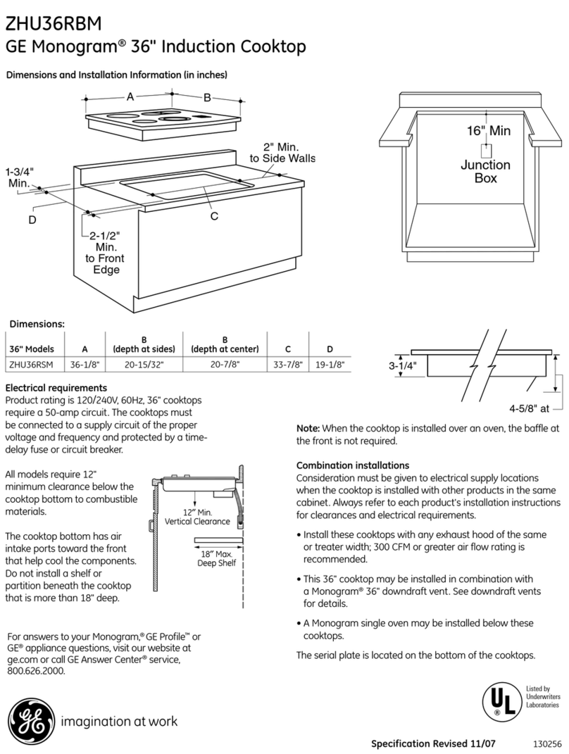
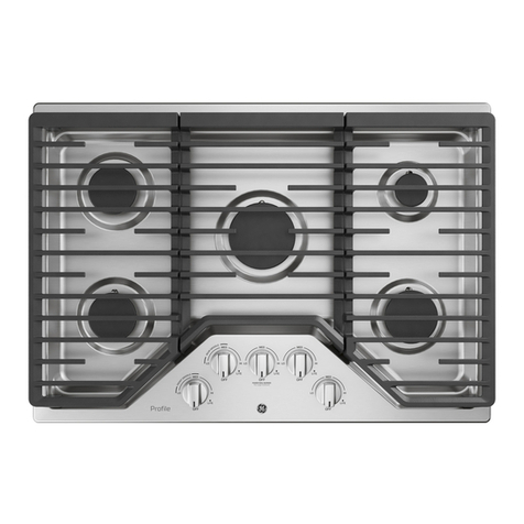
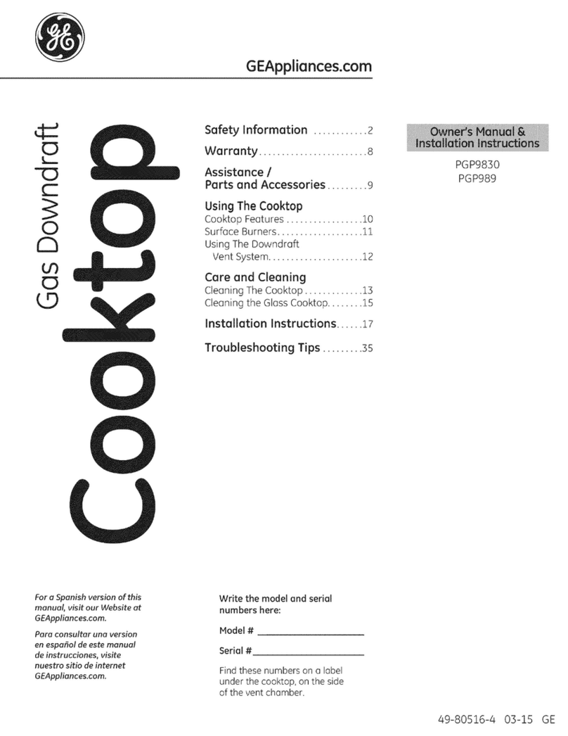
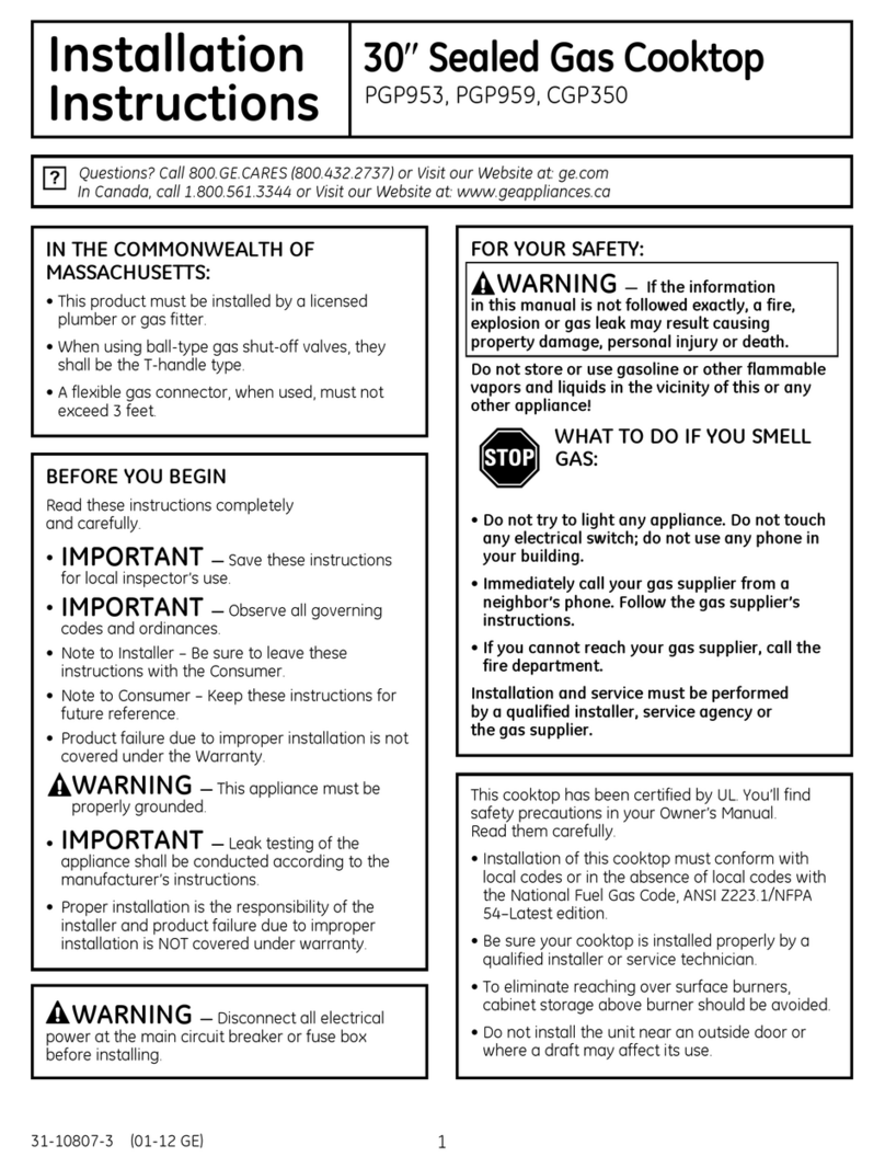
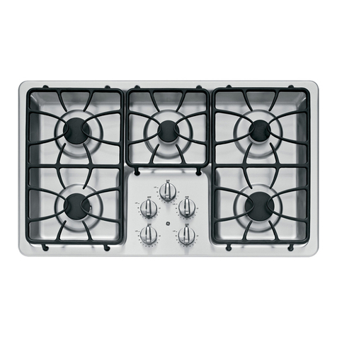
GE PGP989 User manual

Questions? Call 800.GE.CARES (800.432.2737) or Visit our Website at: ge.com
High Altitude Gas Cooktop
Instructions
Read these instructions completely and carefully.
•IMPORTANT –Save these
instructions for local inspector’s use.
•IMPORTANT –Observe all
governing codes and ordinances.
•Note to Installer –Be sure to leave these
instructions with the Consumer.
•Note to Consumer –Keep these
instructions for future reference.
BEFORE YOU BEGIN
•This cooktop is factory set for natural gas operation.
Conversion to high altitude operation should be
performed by a qualified technician or installer. Keep
these instructions for future reference. When converting
to high altitude, save the original parts for possible
future use.
Use the following kit depending on the type of gas
the cooktop is set for:
Natural Gas High Altitude Conversion Kit ........WB28X10114
LP Gas High Altitude Conversion Kit...................WB28X10115
•Product failure due to improper installation is not
covered under the GE Appliance Warranty.
PGP989
WARNING –This conversion kit shall be
installed by a qualified service agency in accordance
with the manufacturer’s instructions and all applicable
codes and requirements of the authority having
jurisdiction. If the information in these instructions
is not followed exactly, a fire, explosion or production of
carbon monoxide may result, causing property damage,
personal injury or loss of life. The qualified service agency
is responsible for the proper installation of this kit. The
installation is not proper and complete until the operation
of the converted appliance is checked as specified in the
manufacturer’s instructions supplied with the kit.
CAUTION –Before proceeding with the
conversion, shut off gas supply to the appliance prior
to disconnecting the electrical power.
FOR YOUR SAFETY:
1
Adjustable wrench 9/32″(7 mm) Nutdriver
TOOLS YOU WILL NEED
T15 Torx driver
PART QUANTITY
Brass orifices 4
Stick-on rating label 1
Installation instructions 1
PARTS INCLUDED WITH KIT
Small, thin-blade flat screwdriver with approximately 1/8″
blade width is needed to access the calibration screw.
49-80561
08-08 JR
Printed in the United States

CONVERT SURFACE BURNERS
First remove, convert and replace the left side surface
burners and then the right side surface burners.
Remove the grates, burner caps and burner heads.
Remove the screws securing the burner bases
to the burners. Pull out the electrodes without
removing the electrode leads.
A
Conversion Instructions
•With the installation of this conversion kit, the cooktop
should operate on either natural gas at 4″of water
column or LP gas at 10″of water column pressure.
•The pressure regulator must be connected in series
with the manifold of the cooktop and must remain in
series with the supply line. For proper operation, the
maximum inlet pressure to the regulator must be no
more than 10″water column pressure for natural gas
and 14″water column pressure for LP gas.
•When checking the regulator, the inlet pressure must
be at least 1″greater than the regulator output
setting. If the regulator is set for 4″of water column
pressure, the inlet pressure must be at least 5″. If the
regulator is set for 10″of water column pressure, the
inlet pressure must be at least 11″.
IMPORTANT –Disconnect the cooktop and
the individual shut-off valve from the gas supply piping
system during any pressure testing of that system at test
pressures greater than 1/2 psig. Isolate the cooktop from
the gas supply piping system by closing the individual
manual shut-off valve to the cooktop during any pressure
testing of the gas supply piping system at test pressures
equal to or greater than 1/2 psig.
GAS SUPPLY
BEFORE YOU BEGIN, TURN OFF THE GAS SUPPLY AT THE
SHUT-OFF VALVE. DISCONNECT THE ELECTRICAL SUPPLY
FROM THE COOKTOP.
TURN OFF GAS AND
ELECTRIC SUPPLY
1
Remove the brass orifice spud in the chimney
of each burner using a 9/32″(7 mm) nutdriver.
B
Grate
Burner cap
Electrode
Burner base
Burner head
Burner base
screw (2)
Install the high altitude orifice spuds in their correct
positions by number.
C
Natural Gas High Altitude Orifices – 5000 ft.
Location BTUs Orifice Size Marking
LF, LR 7644 1.40 mm 140 N
RR 4620 1.12 mm 112 N
RF 9660 1.51 mm 151 N
Shut-off valve
Front
2
Electrical supply
LR
LF
RR
RF
Replace the gaskets, burner bases and electrodes.
Install the two screws in each burner base. Do not
overtighten. The maximum torque is 10 inch pounds.
Push the igniters all the way down into the burner
head.
Install the burner heads, burner caps and grates
in their original burner positions.
E
D
LP Gas High Altitude Orifices – 5000 ft.
Location BTUs Orifice Size Marking
LF, LR 7140 .80 mm 80 L
RR 4620 .66 mm 66 L
RF 9240 .91 mm 91 L

Conversion Instructions
TEST FOR LEAKS
WARNING:DO NOT USE A FLAME TO
CHECK FOR GAS LEAKS! Do not use the cooktop until
all connections have been leak tested.
Perform leak test per the following instructions:
1. Purchase a liquid leak detector or prepare a soap
solution of one part water, one part liquid detergent.
2. When all connections have been made, make sure all
cooktop controls are turned to OFF and turn the gas
supply valve to ON.
3. Apply the liquid leak detector or the soap solution
around all connections from the shut-off valve
to the cooktop.
4. A leak is identified by a flow of bubbles from the
area of the leak.
5. If a leak is detected, turn the gas supply off. Tighten
the fitting. Turn the gas on and test again.
If the leak persists, turn the gas supply off and
contact your dealer for assistance. Do not attempt
to operate the cooktop if a leak is present.
2
3
CHECK IGNITION
Connect electrical supply cord.
Push in one control knob and turn to the LITE
position. The igniter will spark and the burner will
light. The first test may require some time, while air
is flushed out of the gas line.
B
A
3
Check to determine if your burner flames are normal.
If burner flames look like A, call for service. Normal
burner flames should look like B or C, depending on
the type of gas you use. With LP gas, some yellow
tipping on outer cones is normal.
C
Turn the knob to OFF.
Repeat the procedure for each burner.
E
D
A–Yellow flames
Call for service
B–Yellow tips
Normal for
LP gas
C–Soft blue flames
Normal for
natural gas
ADJUST THE LOW FLAME (SIMMER)
SETTING
The top burner valves have low flame/simmer
adjustment screws in the center of the control shafts.
A flashlight may be needed to locate the screw. A small,
thin-blade screwdriver (approximately 1/8″blade width)
is needed to access the screw.
Light two other burners and set the knobs to a
medium to high setting.
Light the burner to be adjusted and turn the knob
to LOW.
B
A
4
Remove the knob and insert a screwdriver into
the valve shaft.
Turn the adjustment screw until the flame reaches the
desired size.
Perform a flame stability test.
Flame Stability Test
Test 1: With the downdraft vent fan on HI, turn the
burner knob from HI to LOW quickly. If the LOW
flame goes out, increase the flame size and test
again.
Test 2: With the burner on the LOW setting, open
and close the cabinet door under the cooktop.
If the flame is extinguished by the air currents
created by the door movement, increase
the flame height and test again.
Flame Recheck
After the adjustment is made, turn off all burners. Ignite
each burner individually. Observe the flame at the HI
position. Rotate the valve to the LOW position and be
sure the flame size decreases as the valve is rotated
counterclockwise.
E
D
C

4
Conversion Instructions

¿Preguntas? Llame al 800.GE.CARES (800.432.2737) o visite nuestro sitio Web en: ge.com
Instrucciones de Estufa de gas
Altitud Elevada
Lea estas instrucciones por completo y con detenimiento.
•IMPORTANTE –Guarde estas
instrucciones para el uso de inspectores locales.
•IMPORTANTE –Cumpla con todos los
códigos y ordenanzas vigentes.
•Nota al instalador –Asegúrese de dejar estas
instrucciones con el consumidor.
•Nota al consumidor –Conserve estas
instrucciones para referencia futura.
ANTES DE COMENZAR
•Esta estufa viene configurada de fábrica para
funcionamiento con gas natural. La conversión a
altitud elevada debe efectuarla un técnico o instalador
calificado. Guarde estas instrucciones para referencia
futura. Cuando efectúe la conversión a altitud elevada,
conserve las piezas originales para un posible uso
futuro.
Utilice el siguiente Kit dependiendo del tipo de gas
para el cual la cocina haya sido diseñada:
Kit de Conversión de Gas Natural
para Altitud Elevada . . . . . . . . . . . . . . . . . . . .WB28X10114
Kit de Conversión de Gas Licuado (LP)
para Altitud Elevada . . . . . . . . . . . . . . . . . . . .WB28X10115
•La Garantía de GE Appliance no cubre las fallas
del producto debido a una instalación incorrecta.
PGP989
ADVERTENCIA –Este kit de
conversión debe ser instalado por una agencia de
servicios calificada de acuerdo con las instrucciones
del fabricante y todos los códigos y requisitos de la
autoridad competente. Si la información de estas
instrucciones no se sigue al pie de la letra, puede
ocasionarse un incendio, una explosión o producción de
monóxido de carbono, generando daños a la propiedad,
lesiones personales o la muerte. La agencia de servicios
calificada es responsable de la adecuada instalación
de este kit. La instalación no resulta adecuada y no
se encuentra completa hasta que se verifique el
funcionamiento del aparato convertido de acuerdo con
las especificaciones de las instrucciones del fabricante
provistas con el kit.
PRECAUCIÓN –Antes de proceder
con la conversión, cierre el suministro de gas del
electrodoméstico antes de desconectar el enchufe
de electricidad.
PARA SU SEGURIDAD:
1
Llave ajustable Llave de tuercas
de 9/32” (7 mm)
HERRAMIENTAS NECESARIAS
Llave Torx T15
PIEZAS CANTIDAD
Orificios de bronce 4
Etiqueta de clasificación adhesiva 1
Instrucciones de instalación 1
PIEZAS INCLUIDAS CON EL KIT
Se necesita un destornillador plano pequeño de lados delgados con una
hoja de aproximadamente 1/8” para llegar al tornillo de calibración.
49-80561
08-08 JR
Impreso en los Estados Unidos

Instrucciones de conversión
•Con la instalación de este kit de conversión, la estufa
debe funcionar con ya sea que se trate de gas natural
con una presión de columna de agua de 4″o gas LP a
una presión de columna de agua de 10″.
•El regulador de presión debe estar conectado en
serie con el colector de la estufa y debe permanecer
en serie con la línea suministro. Para una operación
apropiada, la presión de entrada máxima hacia al
regulador no debe ser mayor de 10″de presión de
columna de agua para gas natural y de 14″para
gas LP.
•Cuando se controla el regulador, la presión de
entrada debe ser por lo menos 1″mayor a la
configuración de salida del regulador. Si el regulador
se configuró para una columna de presión de agua
de 4″, la presión de entrada debe ser de por lo menos
5″. Si el regulador se encuentra configurado para
una presión de columna de agua de 10″, la presión
de entrada debe ser de por lo menos 11″.
IMPORTANTE –Desconecte la estufa y la
válvula individual de apagado del sistema de tuberías de
suministro de gas durante cualquier prueba de presión
del sistema a presiones de prueba mayores a 1/2 psig.
La estufa debe aislarse del sistema de tuberías de
suministro de gas cerrando la válvula individual de
apagado manual hacia la estufa durante cualquier
prueba del sistema de tuberías de suministro de gas
en presiones de prueba iguales o mayores a 1/2 psig.
SUMINISTRO DE GAS
ANTES DE COMENZAR, DESCONECTE
EL SUMINISTRO DE GAS DE LA VÁLVULA
DE APAGADO. DESCONECTE EL SUMINISTRO
DE ELECTRICIDAD DESDE LA ESTUFA.
DESCONECTE EL
SUMINISTRO DE GAS
Y DE ELECTRICIDAD
CONVERSIÓN DE QUEMADORES
DE SUPERFICIE
Primero quite, convierta y reemplace los quemadores
de superficie del lado izquierdo y luego los quemadores
de superficie del lado derecho.
Quite las rejillas, tapas de los quemadores y cabezales
de los quemadores. Saque los tornillos que fijan
las bases de los quemadores a los quemadores. Saque
los electrodos sin quitar los cables del electrodo.
A
1
Quite la copa del orificio de bronce de la chimenea
de cada quemador utilizando una llave de tuercas
de 9/32″(7 mm).
B
Rejilla
Tapa del quemador
Electrodo
Base del quemador
Base del quemador
Tornillo de cabezal
del quemador (2)
Instale las copas de orificios de altitud elevada en sus
posiciones correctas de acuerdo con sus números.
C
Válvula
de apagado
Frente
2
Suministro eléctrico
LR
LF
RR
LF
Orificios de Gas Natural para Altitud Elevada – 5000 pies
Ubicación BTUs Tamaño del Orificio Marca
LF, LR 7644 1.40 mm 140 N
RR 4620 1.12 mm 112 N
RF 9660 1.51 mm 151 N
Orificios de Gas Licuado (LP) para Altitud Elevada – 5000 pies
Ubicación BTUs Tamaño del Orificio Marca
LF, LR 7140 .80 mm 80 L
RR 4620 .66 mm 66 L
RF 9240 .91 mm 91 L
Reemplace las juntas, bases de los quemadores
y electrodos. Instale los dos tornillos en cada base
de quemador. No ajuste de más. El torque máximo
es de 10 libras por pulgada. Empuje los encendedores
bien hacia abajo dentro del cabezal del quemador.
Instale los cabezales de los quemadores, las tapas
de los quemadores y las rejillas en sus posiciones
originales.
E
D

Instrucciones de conversión
PRUEBA DE PÉRDIDAS
ADVERTENCIA:¡NO USE UNA
LLAMA PARA VERIFICAR PÉRDIDAS DE GAS! No utilice
la estufa hasta que se hayan puesto a prueba todas
las conexiones.
Lleve a cabo una prueba de pérdidas según las
siguientes instrucciones:
1. Compre un detector líquido de pérdidas o prepare una
solución jabonosa con mitad agua, mitad detergente líquido.
2. Cuando se hayan realizado todas las conexiones,
asegúrese de que todos los controles de la estufa estén
OFF (apagado) y gire la válvula de suministro de gas a
la posición ON (encendido).
3. Aplique el detector líquido de pérdidas o la solución
jabonosa alrededor de todas las conexiones desde la
válvula de apagado hasta la estufa.
4. Se produce un flujo de burbujas desde el área de la
pérdida cuando se identifica una.
5. Si se detecta una pérdida, cierre el suministro de gas.
Ajuste el accesorio. Vuelva a encender el gas y pruebe
de nuevo.
Si la pérdida persiste, desconecte el suministro de gas y
comuníquese con su vendedor para recibir asistencia. No
trate de utilizar la estufa si se detecta una pérdida.
2
3
CONTROLE EL ENCENDIDO
Conecte el cable de suministro eléctrico.
Presione una perilla de control hacia adentro y gire a
la posición LITE (encendido). El encendedor producirá
chispas y el quemador se encenderá. La primera
prueba puede tomar más tiempo, mientras se purga
el aire de la línea de gas.
B
A
3
Controle para determinar si las llamas del quemador
son normales. Si las llamas se parecen a A, llame
al servicio técnico. Las llamas normales de los
quemadores deben ser como B o C, dependiendo
del tipo de gas que utilice. Con gas LP, es normal
que haya puntas amarillas en los conos externos.
C
Gire la perilla a OFF (apagado).
Repita el procedimiento para cada quemador.
E
D
A–Llamas
amarillas
Llame al servicio
técnico
B–Puntas
amarillas
Normal para gas LP
C–Llamas azules
Normal para gas
natural
AJUSTE LA CONFIGURACIÓN
DE LLAMA BAJA (FUEGO LENTO)
Las válvulas de los quemadores superiores cuentan
con tornillos de ajuste para llama baja/fuego lento
en el centro de las barras de control. Puede necesitarse
una linterna para ubicar el tornillo. Se necesita
un destornillador plano pequeño de lados delgados (hoja
de un ancho de aproximadamente 1/8″) para llegar al
tornillo.
Encienda los otros dos quemadores y configure
las perillas en un nivel medio a alto.
Encienda el quemador que se va a ajustar y gire
la perilla a LOW (baja).
B
A
4
Quite la perilla e introduzca un destornillador dentro
de la barra de la válvula.
Gire el tornillo de ajuste hasta que la llama alcance
el tamaño deseado.
Realice una prueba de estabilidad de llama.
Prueba de estabilidad de llama
Prueba 1: Con el ventilador de corriente descendente en
HI (alta), gire rápidamente la perilla del
quemador de HI (alta) a LOW (baja). Si la llama
LOW (baja) se apaga, aumente el tamaño de la
llama y pruebe de nuevo.
Prueba 2: Con el quemador en la configuración LOW
(baja), abra y cierre la puerta del gabinete
ubicada debajo de la estufa. Si la llama se
apaga por la corriente de aire creada por el
movimiento de la puerta, aumente la altura
de la llama y pruebe de nuevo.
Nueva verificación de la llama
Después de realizado el ajuste, apague todos los
quemadores. Encienda cada quemador en forma
individual. Observe la llama en la posición HI (alta). Gire
la válvula a la posición LOW (baja) y asegúrese de que
el tamaño de la llama disminuya a medida que la válvula
se gira en sentido contrario a las agujas del reloj.
E
D
C

4
Instrucciones de conversión
Other manuals for PGP989
4
Table of contents
Languages:
Other GE Cooktop manuals

GE
GE JP300N User manual

GE
GE Monogram ZGU364NDPSS User manual

GE
GE JGP329 User manual

GE
GE JGP337SEJSS Operating instructions

GE
GE Monogram ZGU366LPSS Manual

GE
GE PGP989 Original instructions

GE
GE Profile PP950 Manual

GE
GE JP256WM2WW Operating instructions

GE
GE JP989 Series Original instructions

GE
GE Profile JP340 User manual
Popular Cooktop manuals by other brands

Miele
Miele SmartLine CS 7612 Operating and installation instructions

Vogue
Vogue 320265 Installation instructions and user guide

Preethi
Preethi INDI COOK instruction manual

Miele
Miele KM6357 Operating and installation instructions

DCS
DCS CT-304WT use and care manual

Brigade
Brigade 30" WideDouble Oven installation guide