Printed in the United States 31-31572 04-16 GE
ADVERTENCIA:
• Retiretodoslos conductoresdecorriente del
electrodoméstico de disyuntor o de la caja del fusible antes
de comenzar con la instalación. Si no cumple conesto,se
podráproducirel riesgo de descargas eléctricas.
• Para reducir el riesgo de descarga eléctrica, incendio o
lesiones a personas, el instalador debe asegurarse de que
el lavaplatos esté completamente cerrado en el momento
de la instalación.
• La conexión inadecuada del conductor de conexión a tierra
del equipamiento puede provocar un riesgo de descarga
HOpFWULFD&RQVXOWHDXQHOHFWULFLVWDFDOL¿FDGRRUHSUHVHQWDQWH
de servicio técnico si tiene dudas sobre la correcta conexión
a tierra del aparato. Si el cableado doméstico no cuenta con
un cable de 2 hilos con conexión a tierra, un instalador debe
realizarunaconexióna tierra.Cuando elcableadodoméstico
esde aluminio,asegúresede usarun compuestoantioxidante
y conectores de aluminio a cobre aprobados por UL.
• Para reducir el riesgo de descarga eléctrica, incendio o
lesiones a personas, el instalador deberá realizar un control
paraasegurar queloscables noestén pellizcadosni dañados,
TXHHOFDEOHDGRGHOKRJDUHVWpFRQHFWDGRDOD¿FKDGHODFDMD
de empalmesa travésde unamortiguador derefuerzo,yque
todas lasconexiones eléctricasrealizadasen elmomentode
la instalación(tuercas paracables)estén dentro delatapa de
la caja de empalmes.
Installation Instructions
Built-In Dishwasher
If you have questions, call 800.GE.CARES (800.432.2737) or visit our Website at: GEAppliances.com.
In Canada, please call 1.800.561.3344 or visit www.geappliances.ca
READ CAREFULLY.
KEEP THESE INSTRUCTIONS.
FOR YOUR SAFETY
Read and observe all WARNINGS and CAUTIONS shown
throughout these instructions. While performing installations
described in this booklet, gloves, safety glasses or goggles
should be worn.
IMPORTANT –Observe all governing codes and
ordinances.
• Note to Installer – Be sure to leave these instructions for the
consumer’s and local inspector’s use.
• Note to Consumer – Keep these instructions with your
Owner’s Manual for future reference.
• Skill Level – Installation of this dishwasher requires
basic mechanical, electrical and plumbing skills. Proper
installation is the responsibility of the installer. Product
failure due to improper installation is not covered under
the GE Appliance Warranty. See warranty information.
• Completion Time – 1 to 3 Hours. New installations require
more time than replacement installations.
IMPORTANT –The dishwasher MUST be installed to
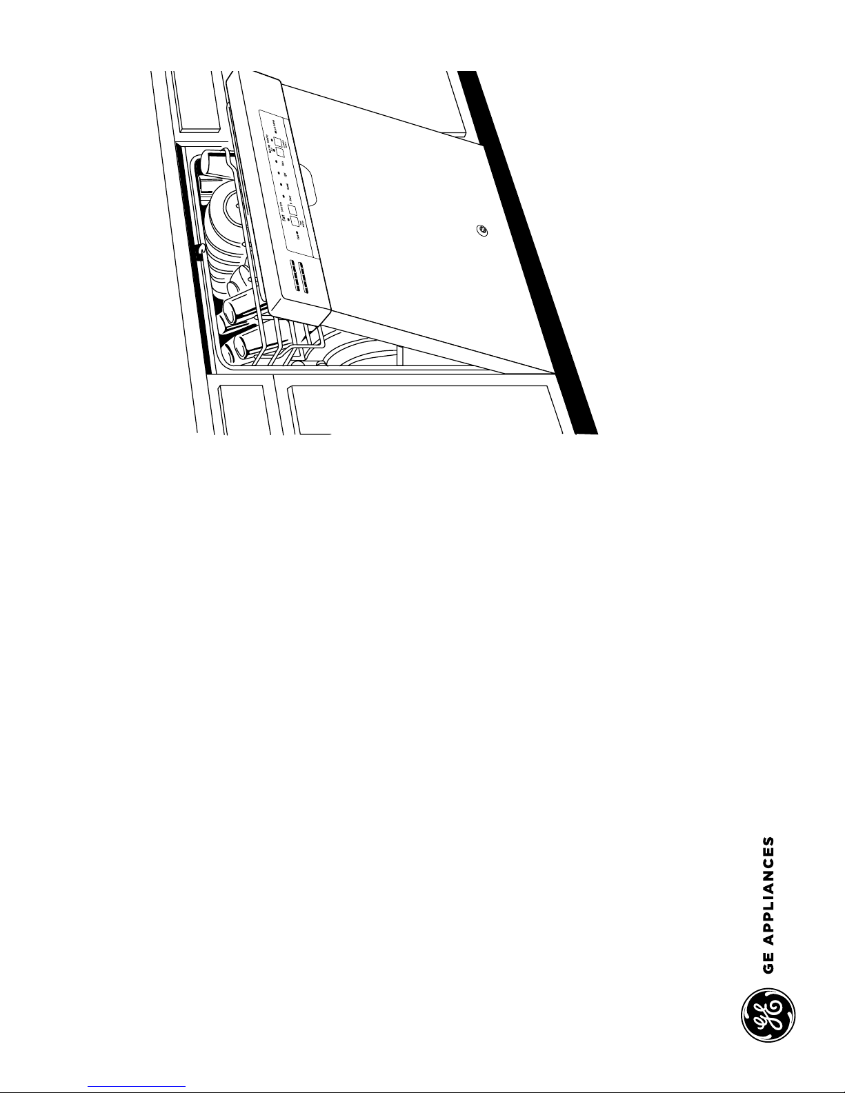
allow for future removal from the enclosure if service is required.
Careshouldbe exercised whentheappliance isinstalledor removed,
to reduce the likelihood of damage to the power supply cord.
If you received a damaged dishwasher, you should immediately
contact your dealer or builder.
Your dishwasher is a water heating appliance.
Optional Accessories – See the Owner’s Manual for available
custom panel kits.
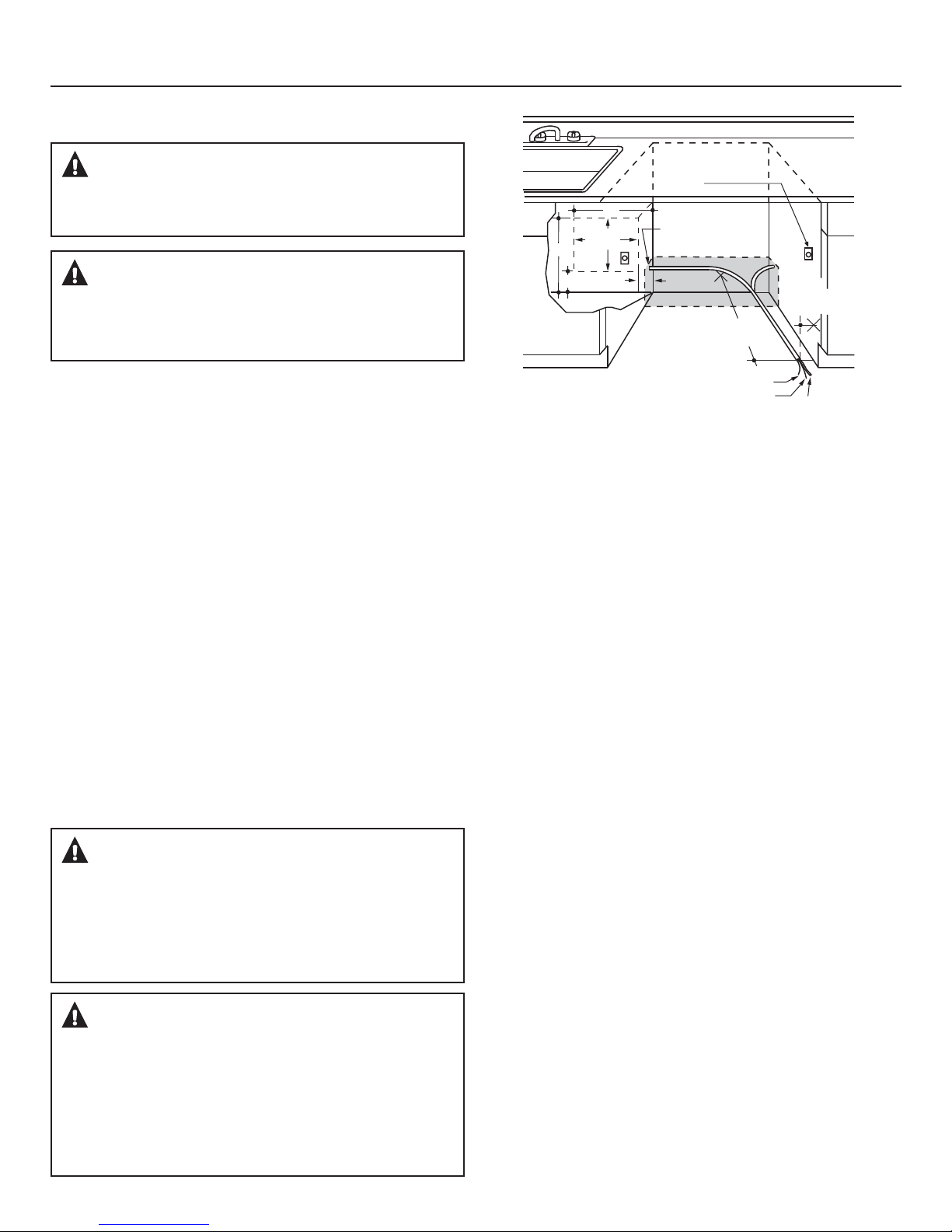
CHECK THE FOLLOWING
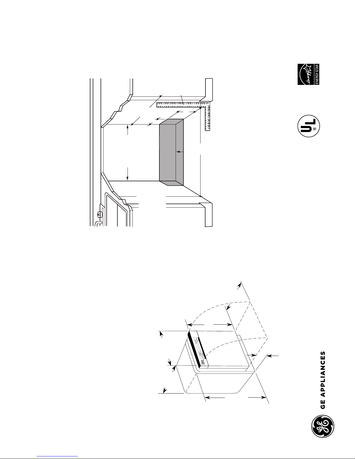
Tub trim does not interfere with the door.
Dishwasher is square and level at both the top and bottom of
the cabinet opening, with no twisting or distortion of the tub
or door.
All 4 legs of the dishwasher are firmly in contact with the floor.
Drain hose is not pinched between the dishwasher and
adjacent cabinets or walls.
Tub trim is fully seated on the tub flange.
BEFORE YOU BEGIN
Read these instructions completely and carefully.
WARNING:
• Remove all power leading to the appliance from the circuit
breaker or fuse box before beginning installation. Failure
to do so can result in a risk of electrical shock.
• 7RUHGXFHWKHULVNRIHOHFWULFVKRFN¿UHRULQMXU\WR
persons, the installer must ensure that the dishwasher is
completely enclosed at the time of installation.
• The improper connection of the equipment grounding
conductor can result in a risk of electric shock. Check
ZLWKDTXDOL¿HGHOHFWULFLDQRUVHUYLFHUHSUHVHQWDWLYHLI\RX
are in doubt that the appliance is properly grounded. If
house wiring is not 2-wire with ground, a ground must be
provided by the installer. When house wiring is aluminum,
be sure to use UL-Listed anti-oxidant compound and
aluminum-to-copper connectors.
• 7RUHGXFHWKHULVNRIHOHFWULFVKRFN¿UHRULQMXU\WR
persons, the installer should check to ensure that wires
are not pinched or damaged, the house wiring is attached
to the junction box bracket through a strain relief, and all
electrical connections made at the time of install (wire
nuts) are contained inside of the junction box cover.