GE GLDT690T How to use

– 2 –
IMPORTANT SAFETY NOTICE
The information in this service guide is intended for use by
individuals possessing adequate backgrounds of electrical,
electronic, and mechanical experience. Any attempt to repair a
major appliance may result in personal injury and property
damage. The manufacturer or seller cannot be responsible for the
interpretation of this information, nor can it assume any liability in
connection with its use.
WARNING
To avoid personal injury, disconnect power before servicing
this product . If electrical power is required for diagnosis or test
purposes, disconnect the power immediately after performing the
necessary checks.
RECONNECT ALL GROUNDING DEVICES
If grounding wires, screws, straps, clips, nuts, or washers used to
complete a path to ground are removed for service, they must be
returned to their original position and properly fastened.
GE Appliances
Copyright © 2011
All rights reserved. This service guide may not be reproduced in w hole or in part
in any form without written permission from the General Electric Company.
https://appliancetechmanuals.com

– 3 –
Table of Contents
Bottom Door Seal..............................................................................................................................................................20
Component Locator Views...........................................................................................................................................12
Control Assembly ..............................................................................................................................................................17
Control Board Connector Locator View .................................................................................................................15
Control Features................................................................................................................................................................ 7
Control Panel.......................................................................................................................................................................16
Detergent/ Rinse Module................................................................................................................................................19
Dishwasher Components..............................................................................................................................................16
Door Switch Assembly ...................................................................................................................................................18
Drain Pump Assembly ....................................................................................................................................................26
Factory Diagnostic Mode..............................................................................................................................................31
Fill Funnel..............................................................................................................................................................................23
Heating Element................................................................................................................................................................21
Inner Door Panel ...............................................................................................................................................................20
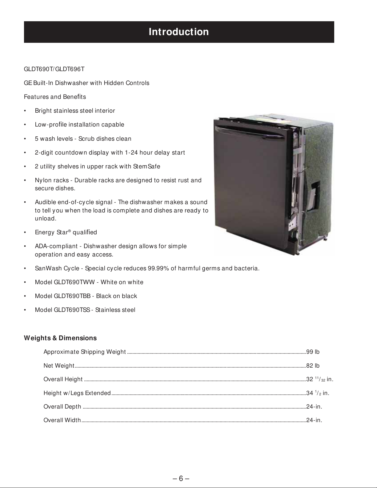
Introduction ......................................................................................................................................................................... 6
Motor Pump Assembly ...................................................................................................................................................27
Nomenclature .................................................................................................................................................................... 5
Outer Door Panel ..............................................................................................................................................................16
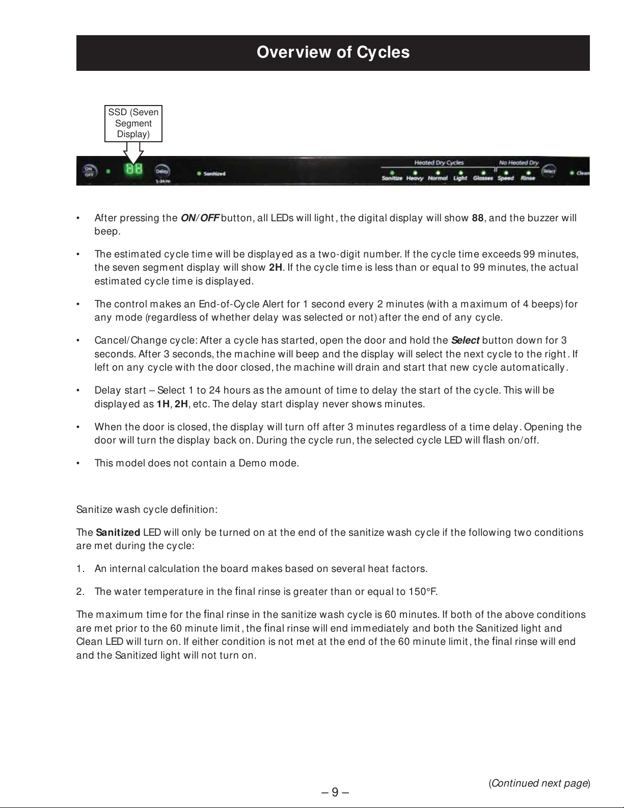
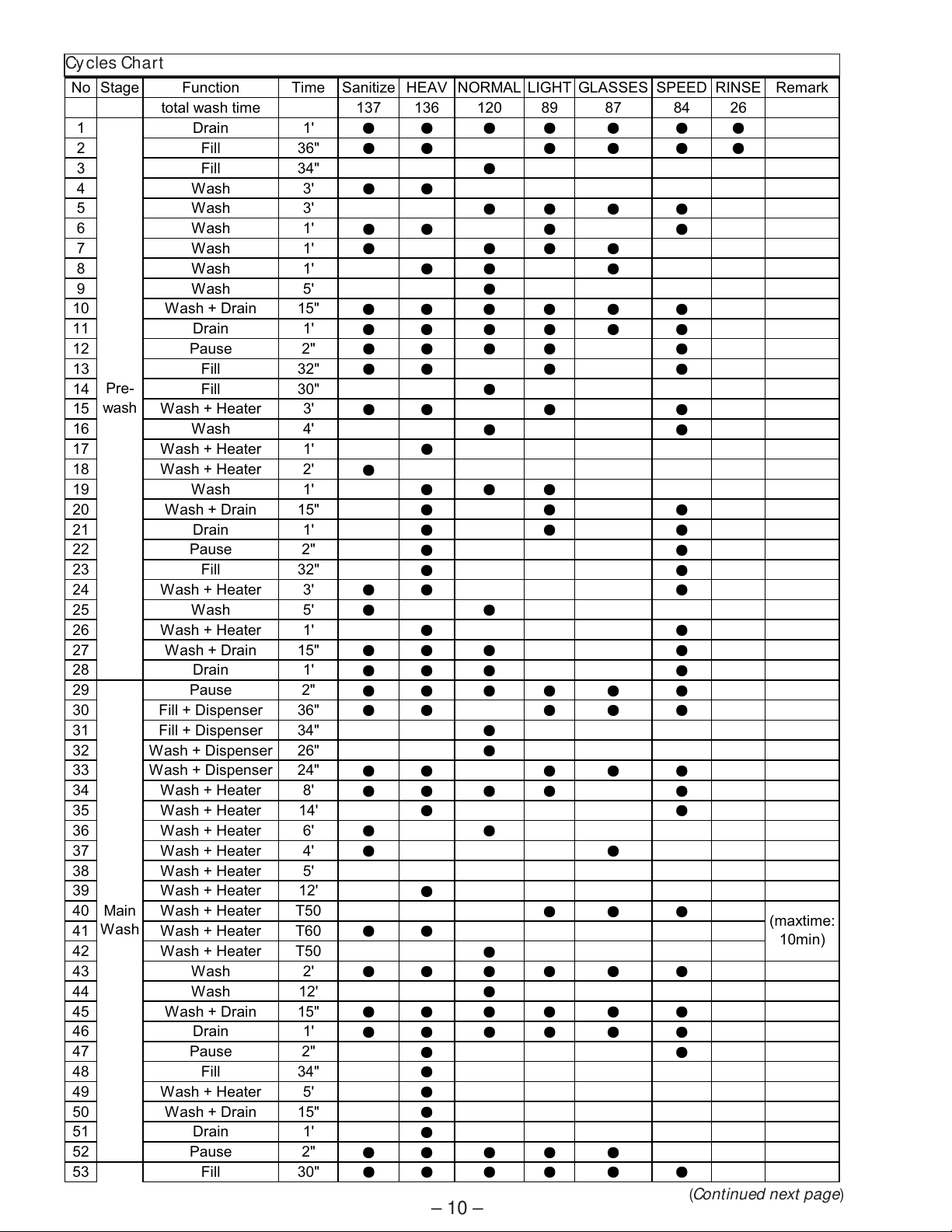
Overview of Cy cles .......................................................................................................................................................... 9
Pressure Switch .................................................................................................................................................................25
Schematics and Wiring Diagrams............................................................................................................................33
Service Test Mode.............................................................................................................................................................32
Specifications .....................................................................................................................................................................32
Static Dry System .............................................................................................................................................................16
Sump Assembly .................................................................................................................................................................29
Therm istor ............................................................................................................................................................................28
https://appliancetechmanuals.com

– 4 –
Troubleshooting ...............................................................................................................................................................31
Tub Gasket and Trim .......................................................................................................................................................21
Warranty ..............................................................................................................................................................................34
Water Inlet Valve...............................................................................................................................................................24
https://appliancetechmanuals.com

– 5 –
Platform
4-6 = GE tall tub
G L D T 6 9 0 T B B
Product Type
GLD = GE long door
Exterior Color
BB = Black
CC = Bisque
SS = Stainless Steel
WW = White
Model Year Designator
Model Number
The nomenclature plate is located on
the left side of the tub wall, inside the
door jamb.
The mini-manual is located in a
plastic bag taped on the back side of
the toe kick.
Nomenclature
Nomenclature
Door
0 = Color door
6 = Stainless door
Feature Pack
Top Control
Serial Number
The first two characters of the serial number
identify the month and y ear of manufacture.
Example: MV123456S = May, 2011
M- JUL
R - AUG
S - SEP
T - OCT
V - NOV
Z - DEC
A - JAN
B - FEB
F - MAR
G - APR
H - MAY
L - JUN
2011 - V
2010 - T
2009 - S
2008 - R
2007 - M
2006 - L
2005 - H
2004 - G
2003 - F
2002 - D
2001 - A
2000 - Z
The letter designating
the year repeats every
12 years.
Example:
V - 2011
V - 1999
V - 1987
https://appliancetechmanuals.com

– 6 –
GLDT690T/ GLDT696T
GE Built-In Dishwasher with Hidden Controls
Features and Benefits
• Bright stainless steel interior
• Low-profile installation capable
• 5 wash levels - Scrub dishes clean
• 2-digit countdown display with 1-24 hour delay start
• 2 utility shelves in upper rack with StemSafe
• Ny lon racks - Durable racks are designed to resist rust and
secure dishes.
• Audible end-of-cycle signal - The dishwasher makes a sound
to tell you when the load is complete and dishes are ready to
unload.
• Energy Star®qualified
• ADA-compliant - Dishwasher design allows for simple
operation and easy access.
• SanWash Cy cle - Special cycle reduces 99.99% of harmful germs and bacteria.
• Model GLDT690TWW - White on white
• Model GLDT690TBB - Black on black
• Model GLDT690TSS - Stainless steel
Weights & Dimensions
Approximate Shipping Weight .........................................................................................................................................99 lb
Net Weight.................................................................................................................................................................................82 lb
Overall Height ..........................................................................................................................................................................32 11/32 in.
Height w /Legs Extended.....................................................................................................................................................34 1/2in.
Overall Depth ...........................................................................................................................................................................24-in.
Overall Width............................................................................................................................................................................24-in.
Introduction
https://appliancetechmanuals.com

– 7 –
Throughout this manual, features and appearance may vary from your model.
Control Features
About the dishwasher control panel.
Control Settings
2
3
16
ON/ OFF
With door open, press ON/ OFF button to turn the unit ON to begin operation and OFF at the end of a wash cycle.
The ON/ OFF light is displayed when the dishwasher is ON.
Wash Cycle Selections
Press SELECT button to choose wash cycle. The light under the cycle name will display to indicate which cycle has been selected.
NOTE: All
cycle times and water usage information contained in this section are approximate values. Actual results will depend
on several factors including, but not limited to, inlet water temperature and household water pressure.
1
2
SANITIZE 4.82 gal., 130 minutes
This cycle is meant to sanitize dishes and glasses with added heat . If you select sanitize cycle, at the end
of this cycle, the sanitized indicator will turn on .
HEAVY 6.74 gal., 125 min.
T
his cycle is meant for heavily soiled dishes or cookware with dried-on or baked-on soils. This
cycle may not remove burned-on foods. Everyday dishes are safe to be used in this cycle.
NORMAL 4.65 gal., 115 min.
T
his cycle is meant for loads of everyday dishes, glasses and cookware with medium soils that have not been pre-
rinsed.
LIGHT 4.82 gal., 78 min.
T
his cycle is meant for loads of everyday dishes, glasses and cookware with light soils that have been pre-rinsed.
GLASSES 3.89 gal., 76 min.
T
his cycle is meant for lightly soiled glassware. This cycle has less heating during the wash and rinse to protect
your glassware. This cycle also has a lower temperature heated dry.
SPEED 5.75 gal., 78 min.
T
his cycle is meant for loads of everyday dishes, glasses and cookware with medium soils that have not been pre-
rinsed. This cycle features reduced wash times to allow for faster cycle completion. This cycle also has a reduced
time heated dry.
RINSE 1.92 gal., 26 min.
F
or rinsing partial loads that will be washed later. Do not use detergent with this cycle. This cycle does not include
heated dry.
4
6
(Continued next page)
https://appliancetechmanuals.com

– 8 –
Delay Start Option
This option allows you to delay the start of a wash cycle for up to 24 hours.
With the door open, turn the dishwasher ON by pressing the ON/ OFF button; then press the DELAY button to choose
the number of hours you want to delay the start of the wash cycle. The hours will show in the display window.
N
OTE: To cancel the DELAY HOURS option before the start of the cycle, repeatedly press the DELAY HOURS button
until the display is blank or reads “00.”
2 Digit Display
This display is used for DELAY START and cycle time countdown.
When a cycle is selected, this display is populated with the total number of minutes in the cycle (up to 99 minutes).
For cycle times above 99 minutes the display will read “99”.
Starting a Cycle
After selecting the wash cycle (Step 2) and DELAY START (Step 3), if desired, close the door of the
dishwasher to start the cycle or begin the DELAY START countdown. When the door is closed, there will be a 5
second delay followed by a 60 second pump out before the water fill begins.
Status Indicators
SANITIZED If the SANITIZEcycle is selected, the sanitized indicator light will be turned on at the end
of the cycle. If the NSF requirements for sanitization are not reached, the light will not
turn on.
CLEAN
The green light will display and a beep will sound to alert you that the wash cycle is complete.
If the door is NOT opened, the beep will sound 4 times.
6
5
3
4
GEAppliances.com
https://appliancetechmanuals.com

– 9 –
Overview of Cycles
• After pressing the ON/ OFF button, all LEDs will light , the digital display will show 88, and the buzzer will
beep.
• The estimated cycle time will be displayed as a two-digit number. If the cycle time exceeds 99 minutes,
the seven segment display will show 2H. If the cy cle time is less than or equal to 99 minutes, the actual
estimated cycle time is displayed.
• The control makes an End-of-Cycle Alert for 1 second every 2 minutes (with a maximum of 4 beeps) for
any mode (regardless of whether delay was selected or not) after the end of any cycle.
• Cancel/ Change cycle: After a cycle has started, open the door and hold the Select button down for 3
seconds. After 3 seconds, the machine will beep and the display will select the next cycle to the right . If
left on any cycle with the door closed, the machine will drain and start that new cycle automatically .
• Delay start – Select 1 to 24 hours as the amount of time to delay the start of the cycle. This will be
displayed as 1H, 2H, etc. The delay start display never shows minutes.
• When the door is closed, the display will turn off after 3 m inutes regardless of a time delay . Opening the
door will turn the display back on. During the cycle run, the selected cycle LED will flash on/off.
• This model does not contain a Demo mode.
Sanitize wash cycle definition:
The Sanitized LED will only be turned on at the end of the sanitize wash cycle if the following two conditions
are met during the cycle:
1. An internal calculation the board m akes based on several heat factors.
2. The water temperature in the final rinse is greater than or equal to 150°F.
The maximum time for the final rinse in the sanitize wash cycle is 60 minutes. If both of the above conditions
are met prior to the 60 minute limit , the final rinse will end immediately and both the Sanitized light and
Clean LED will turn on. If either condition is not met at the end of the 60 minute limit , the final rinse will end
and the Sanitized light will not turn on.
(Continued next page)
SSD (Seven
Segment
Display)
https://appliancetechmanuals.com

– 10 – (Continued next page)
No Stage Function Time Sanitize HEAV NORMAL LIGHT GLASSES SPEED RINSE Remark
total wash time 137 136 120 89 87 84 26
1Drain1'
ƽƽƽƽƽƽƽ2 Fill 36" ƽƽƽƽƽƽ3 Fill 34" ƽ4Wash3'
ƽƽ5Wash3' ƽƽƽƽ6Wash1'
ƽƽƽƽ7Wash1'
ƽƽƽƽ8Wash1'ƽƽƽ9Wash5' ƽ10 Wash + Drain 15" ƽƽƽƽƽƽ11 Drain 1' ƽƽƽƽƽƽ12 Pause 2" ƽƽƽƽƽ13 Fill 32" ƽƽƽƽ14 Fill 30" ƽ15 Wash + Heater 3' ƽƽƽƽ16 Wash 4' ƽƽ17 Wash + Heater 1' ƽ18 Wash + Heater 2' ƽ19 Wash 1' ƽƽƽ20 Wash + Drain 15" ƽƽƽ21 Drain 1' ƽƽƽ22 Pause 2" ƽƽ23 Fill 32" ƽƽ24 Wash + Heater 3' ƽƽƽ25 Wash 5' ƽƽ26 Wash + Heater 1' ƽƽ27 Wash + Drain 15" ƽƽƽƽ28 Drain 1' ƽƽƽƽ29 Pause 2" ƽƽƽƽƽƽ30 Fill + Dispenser 36" ƽƽƽƽƽ31 Fill + Dispenser 34" ƽ32 Wash + Dispenser 26" ƽ33 Wash + Dispenser 24" ƽƽƽƽƽ34 Wash + Heater 8' ƽƽƽƽƽ35 Wash + Heater 14' ƽƽ36 Wash + Heater 6' ƽƽ37 Wash + Heater 4' ƽƽ38 Wash + Heater 5'
39 Wash + Heater 12' ƽ40 Wash + Heater T50 ƽƽƽ41 Wash + Heater T60 ƽƽ42 Wash + Heater T50 ƽ43 Wash 2' ƽƽƽƽƽƽ44 Wash 12' ƽ45 Wash + Drain 15" ƽƽƽƽƽƽ46 Drain 1' ƽƽƽƽƽƽ47 Pause 2" ƽƽ48 Fill 34" ƽ49 Wash + Heater 5' ƽ50 Wash + Drain 15" ƽ51 Drain 1' ƽ52 Pause 2" ƽƽƽƽƽ53 Fill 30" ƽƽƽƽƽƽ(maxtime:
10min)
Pre-
wash
Main
Wash
Cycles Chart
https://appliancetechmanuals.com

– 11 –
54 Wash 8' ƽƽƽƽ55 Wash + Heater 3' ƽƽƽƽ56 Wash + Heater 2' ƽƽƽƽ57 Wash + Drain 15" ƽƽƽƽƽƽƽ58 Drain 1' ƽƽƽƽƽƽƽ59 Pause 2" ƽƽƽƽƽƽƽ60 Fill + Dispense 30" ƽƽƽƽƽƽƽ61 Wash + Dispense 30" ƽƽƽƽƽƽƽ62 Wash + Heater 4' ƽƽƽƽƽƽƽ63 Wash + Heater 3' ƽƽƽƽƽƽƽ64 Wash + Heater 30" ƽƽƽƽƽƽƽ65 Wash + Heater T50 ƽƽ(maxtime:
3min)
66 Wash + Heater T60 ƽƽ(maxtime:
8min)
67 Wash + Heater T67 ƽ(maxtime:
20min)
68 Wash + Heater 7' ƽ69 Wash 1' ƽƽƽƽƽƽ70 Wash 1' ƽƽƽƽƽ71 Wash + Drain 15" ƽƽƽƽƽƽƽ72 Drain 90" ƽƽƽƽƽƽƽ73 Pause 2" ƽƽƽƽƽƽ74 Heating Dry 3' ƽƽƽƽƽƽ75 Pause 1' ƽƽƽƽƽƽ76 Heating Dry 3' ƽƽƽƽƽ77 Pause 1' ƽƽƽƽƽ78 Heating Dry 1' ƽƽƽƽƽ79 Pause 1' ƽƽƽƽƽ80 Heating Dry 1' ƽƽƽƽƽ81 Pause 3' ƽƽƽƽƽ82 Heating Dry 1' ƽƽƽƽƽ83 Pause 3' ƽƽƽƽƽ84 Heating Dry 1' ƽƽƽƽƽ85 Pause 3' ƽƽƽƽƽ86 Heating Dry 1' ƽƽƽƽƽ87 Pause 3' ƽƽƽƽƽ88 Heating Dry 1' ƽƽƽƽƽ89 Pause 3' ƽƽƽƽƽ90 Heating Dry 1' ƽƽƽƽ91 Pause 1' ƽƽƽƽ92 Heating Dry 1' ƽƽƽƽ93 Pause 1' ƽƽƽƽ94 Heating Dry 1' ƽƽƽƽƽƽ95 Pause 8' ƽƽƽƽƽƽnote: 1' means 1 minute, 2" means 2 seconds, T50 means 50degC
Dry
Rinse
No Stage Function Time Sanitize HEAV NORMAL LIGHT GLASSES SPEED RINSE Remark
Cycles Chart
https://appliancetechmanuals.com

– 14 –
Interior View of Basin (With Racks Removed) Right Side View (Insulation Removed)
Bottom View (Looking Up)
Note: Drain hose is shown in shipping configuration.
Sump
Spray Arm
Heating Element
Filter Assembly
Micro-Filter
Clamp Nut
Fill Hose
Pressure
Switch Hose
Fill Funnel
Wash Pump Assembly
Capacitor
Pressure
Switch
Water Inlet Valve
Front
Back
Drain Pump
Pressure
Switch
Drain Hose
Thermistor
https://appliancetechmanuals.com

– 15 –
Control Board Connector Locator View
CN5
CN2
P6
P4
CN4
CN3
CN1
CN4 and CN5 - PCB user interface boards
P4 - L1
P6 - 120 VAC output to heater
CN1 - Door Switch
CN2 - 120 VAC output:
Pin 1 = pressure switch; Pin 3 = water inlet valve;
Pin 5 = detergent/ rinse module; Pin 7 = drain
pump; Pin 9 = motor pump.
CN3 - Therm istor
https://appliancetechmanuals.com

– 16 –
Dishwasher Components
Control Panel
To remove the control panel:
1. Remove the outer door panel. (See Outer Door
Panel.)
2. Remove 2 Phillips-head screws from door latch.
Outer Door Panel
The outer door panel covers the door to the
dishwasher and must be removed to access the
control panel, detergent/rinse module, bottom door
seal, and heating element .
To remove the outer door panel, remove 12 Phillips-
head screws, and then lower the door panel from
the control panel.
3. Tilt the control panel out to clear lip and remove.
Note: The escutcheon console cover or top trim with
lettering is replaced using adhesive.
Static Dry System
The static dry system operates through a vent
located behind the left side door panel. The vent
allows hot air to exit the dishwasher tub and
gradually remove moisture that runs through the
tube and back into the tub.
To remove the static dry system:
1. Remove the control panel. (See Control Panel.)
2. Turn the static dry vent cover counterclockwise
and remove.
Vent
Cover
(Continued next page)
https://appliancetechmanuals.com

– 17 –
Note:
• Inspect the cover for hard water/lime deposits
or debris, and clean if necessary.
• If the control panel gasket shows obvious signs
of w ear or damage, replace the gasket .
• If the vent cover O-ring shows obvious signs of
wear or damage, replace the static dry vent .
Static Dry Vent
O-Ring
Control Assembly
The control assembly consists of 2 PCB user
interface boards and a power board.
To remove the PCB user interface assembly:
1. Disconnect the power supply to the dishwasher.
2. Remove the control panel. (See Control Panel.)
3. Remove the 2 Phillips-head screws that attach
the power board cover to the power board.
(Continued next page)
Static Dry Vent
3. Pull the top of the vent out while lifting up to
clear the bottom of the dishwasher.
Disconnect
4. Disconnect 2 wire harnesses from the power
board.
5. Cut the plastic tie that holds the wires to the
control panel.
6. Remove 3 Phillips-head screws from the cycle
select PCB user interface board.
https://appliancetechmanuals.com

– 18 –
To remove the power board assembly:
1. Disconnect the power supply to the dishwasher.
2. Remove the control panel. (See Control Panel.)
3. Remove the 2 Phillips-head screws that attach
the power board cover to the power board.
4. Disconnect the wire harnesses from the power
board.
5. Remove the 2 Phillips-head screws that attach
the power board assembly to the housing.
Door Switch Assembly
The door switch assembly consists of 2 switches
activated by a spring-loaded plunger. One door
switch connects or disconnects the line (hot) side of
120 VAC. The other switch connects or disconnects
the neutral side of 120 VAC.
WARNING: Power remains applied to the controller
location at CN1, Pin 1 to 3, while the door is open
(unlatched).
When the door is in the closed position, the door
latch presses and holds down the switch plunger
on the door switch assembly. This action holds the
door firmly against the seal, and the normally open
contacts of the door switches are closed.
To remove the door switch assembly:
1. Disconnect the power supply to the dishwasher.
2. Remove the control panel. (See Control Panel.)
3. Disconnect the 4 wiring harnesses from the door
switch.
4. Remove the 2 Phillips-head screws that hold the
door switch assembly to the control panel.
7. Remove 2 Phillips-head screws from the display
PCB user interface board.
Disconnect
https://appliancetechmanuals.com

– 19 –
Detergent/ Rinse Module
The control panel must be removed to access the
detergent/ rinse module. (See Control Panel.)
The detergent/ rinse module is connected by 2 wires
and held in place by 6 Phillips-head screws and 2
brackets.
The detergent/ rinse module operates on 120 VAC
and has an approximate resistance value of 2 K
The detergent/ rinse m odule automatically
dispenses both the detergent and the rinse agent at
the appropriate times. The module is activated twice
during a wash cycle. Detergent is dispensed at the
beginning of the main wash cycle and rinse agent at
the beginning of the final rinse.
Operation of the detergent/ rinse module can be
checked by using the service test mode. (See Service
Test Mode.)
The first time the module is activated, the lever
slides up the right-hand path of the connecting rod
(1). This action releases the detergent cover.
When deactivated, the lever returns down the left-
hand path and comes to rest under the notch (2) in
the center of the connecting rod.
At the second activation, the lever lifts the
connecting rod by the notch. This action lifts the
rinse dispenser plunger (3) and releases the rinse
agent . When deactivated, the lever returns to its
original starting position.
1
2
3
Note: Make sure the rubber seal is retained in the
recessed groove before reinstalling the module to
the door assembly.
Bracket
Bracket
Disconnect
Disconnect
Seal
https://appliancetechmanuals.com

– 20 –
Inner Door Panel
To remove the inner door panel:
1. Disconnect power.
2. Remove the control panel. (See Control Panel.)
3. Remove the detergent/rinse module. (See
Detergent/ Rinse Module.)
4. Remove the 4 Phillips-head screws (2 on each
side) that attach the inner door panel to the
bottom door bracket .
Note: When installing the inner door, place a pair
of pliers into the bottom door bracket to prevent it
from closing.
Bottom Door Seal
The bottom door seal prevents water leakage by
sealing between the bottom of the door and the
tub. It is not replaced as a separate part on this
dishwasher. It is replaced as part of the inner door
panel. (See Inner Door Panel.)
https://appliancetechmanuals.com
Other manuals for GLDT690T
4
This manual suits for next models
1
Table of contents
Other GE Dishwasher manuals

GE
GE GBF 630 Series User manual

GE
GE Profile PDW9000 Series User manual

GE
GE Profile PDW8900 Series User manual

GE
GE Monogram ZBD6400 Series User manual

GE
GE Dishwashers User manual

GE
GE GLDT696D00SS User manual

GE
GE ADW1000 Series User manual

GE
GE Triton GSD5900G User manual

GE
GE Monogram ZBD1800G User manual

GE
GE Spacemaker GSM603 User manual