GE Profile PDW9200 Series How to use

PUB # 31-9113-1 03/04
Replaces PUB # 31-9113
MODEL SERIES:
TECHNICAL SERVICE GUIDE
Top Control
Profile Dishwashers
PDW9200
PDW9280
PDW9700
PDW9800
PDW9880
GE Consumer & Industrial

– 2 –
IMPORTANT SAFETY NOTICE
The information in this service guide is intended for use by
individuals possessing adequate backgrounds of electrical,
electronic, and mechanical experience. Any attempt to repair a
major appliance may result in personal injury and property
damage. The manufacturer or seller cannot be responsible for the
interpretation of this information, nor can it assume any liability in
connection with its use.
WARNING
To avoid personal injury, disconnect power before servicing this
product. If electrical power is required for diagnosis or test purposes,
disconnect the power immediately after performing the necessary
checks.
RECONNECT ALL GROUNDING DEVICES
If grounding wires, screws, straps, clips, nuts, or washers used to
complete a path to ground are removed for service, they must be
returned to their original position and properly fastened.
GE Consumer & Industrial
Technical Service Guide
Copyright © 2004
All rights reserved. This service guide may not be reproduced in whole or in part
in any form without written permission from the General Electric Company.

– 3 –
Active Vent.......................................................................................................................21
Circulation Pump and Motor ............................................................................................13
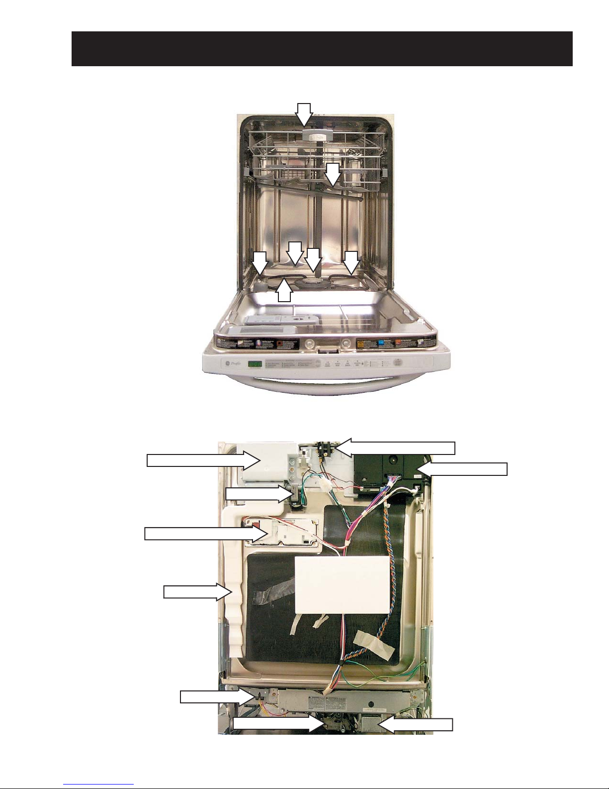
Component Locator Views.................................................................................................9
Components ....................................................................................................................11
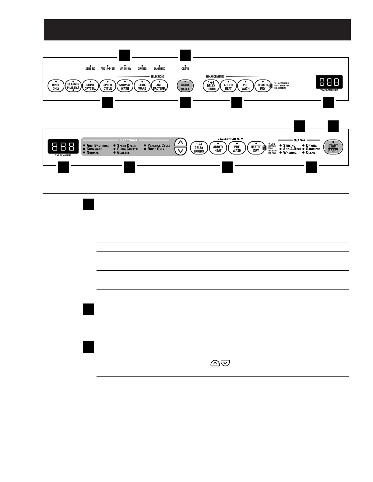
Control Features................................................................................................................5
Control Module ................................................................................................................19
Control Module Board......................................................................................................19
Demo Mode .....................................................................................................................14
Detergent/Rinse Module .................................................................................................20
Door Interlock Switch ......................................................................................................20
Door Panel ......................................................................................................................18
Drain System ...................................................................................................................16
Factory Test Mode ...........................................................................................................23
Fan...................................................................................................................................21
Fill Funnel ........................................................................................................................12
Heating Element ..............................................................................................................14
Lower Spray Wash Arm, Fine Filter, and Inlet Cover.......................................................12
Main Conduit ...................................................................................................................12
Membrane Keypad ..........................................................................................................18
Middle Spray Arm ............................................................................................................11
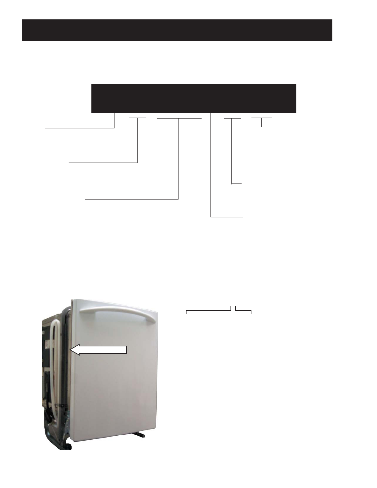
Nomenclature ...................................................................................................................4
Schematic........................................................................................................................26
Service Mode...................................................................................................................22
Strip Circuits ....................................................................................................................25
Transorb ..........................................................................................................................17
Troubleshooting ..............................................................................................................24
Turbidity Sensor...............................................................................................................15
Upper Spray Arm .............................................................................................................12
Using the Dishwasher with the Upper Rack Removed.................................................... 11
Wash Cycles....................................................................................................................13
Warranty .........................................................................................................................27
Water Valve and Flood Switch ........................................................................................16
Water Valve Test .............................................................................................................17
Table of Contents

– 4 –
Model Designator
Designates features – the higher
the number, the more features.
The letter designating
the year repeats every
12 years.
Example:
T - 1974
T - 1986
T - 1998
P D W 9 2 0 0 J 0 0 W W
Brand
P = Profile
Product Type
DW = Dishwasher
Exterior Color
BB = Black
CC = Bisque
SS = Stainless Steel
WW = White
II = Integrated*
Model Year Designator
Engineering Model Suffix
Model Number
The first two characters of the serial number
identify the month and year of manufacture.
Example: AG123456S = January, 2004
A- JAN 2005 - H
D - FEB 2004 - G
F - MAR 2003 - F
G - APR 2002 - D
H - MAY 2001 - A
L - JUN 2000 - Z
M - JUL 1999 - V
R - AUG 1998 - T
S - SEP 1997 - S
T - OCT 1996 - R
V - NOV 1995 - M
Z - DEC 1994 - L
Note: The service information sheet is located
under the control panel.
Serial Number
The model number and serial number are located inside the door jam. The mini-manual is located behind
the toe-plate.
*Note: The exterior color,
II = Integrated, requires a
panel kit.
Nomenclature
Nomenclature

– 5 –
Control Settings
Status Indicator Lights (Indicators vary by models)
The Status display tells you what is happening while the dishwasher is in operation and may flash,
indicating a malfunction. The lights will come ON indicating the sequence of the dishwasher operation.
SENSING Displayed while the ExtraClean
™
Sensor is measuring the amount of soil and temperature of water.
The dishwasher will adjust the selected cycle to achieve optimal performance.
ADD-A-DISH Displayed during prewash indicating that dishes added now will still be cleaned.
WASHING Displayed during prewash, main wash and rinse periods.
RINSING Displayed during rinse periods.
DRYING Displayed during HEATED DRY.
SANITIZED Displayed when cycle has met sanitization conditions.
CLEAN Displayed when a wash cycle is complete and enhancements are complete.
Time Remaining Display (on some models)
During operation, the display shows the minutes remaining until the cycle is complete. The display
may adjust the remaining time while the Sensing light is on. During a delay start, the display will show
hours of time remaining until the cycle starts.
Selections
PDW8100–PDW8800 Series: Press the pad for the desired wash cycle.
PDW9200–PDW9800 Series: Use the Arrow Pads to scroll through the wash cycles.
The light above or next to the selected pad will be ON to indicate which WASH CYCLE has been selected.
ANTI-BACTERIA Heavy 10.0 gal., 93 min.
(on some models) Medium 8.6 gal., 90 min.
Light 7.2 gal., 90 min.
This cycle raises the water temperature in the final rinse to sanitize your dishware. The cycle length
will vary depending on the temperature of your inlet water.
NOTE: The Anti-Bacteria cycle is monitored for sanitization requirements. If the cycle is interrupted
during or after the main wash portion or if the incoming water temperature is so low that adequate
water heating cannot be achieved, the sanitizing conditions may not be met. In these cases, the
sanitized light will not illuminate at the end of the cycle.
NOTE: NSF-certified residential dishwashers are not intended for licensed food establishments.
3
2
1
1
23 45
6
5
62 43
1
PDW8100–PDW8800 Series
PDW9200–PDW9800 Series
Control Features

– 6 –
Selections (continued)
COOKWARE Heavy 11.4 gal., 95 min.
(POTS & PANS) Medium 10.0 gal., 71 min.
Light 10.0 gal., 66 min.
This cycle is meant for heavily soiled dishes or cookware with dried-on or baked-on soils.
This cycle may not remove burned-on foods. Everyday dishes are safe to be used in this cycle.
NORMAL WASH Heavy 9.9 gal., 74 min.
Medium 7.0 gal., 61 min.
Light 5.6 gal., 48 min.
This cycle is for medium/heavily soiled dishes and glassware.
SPEED CYCLE Heavy 9.3 gal., 36 min.
(on some models) Medium 7.2 gal., 36 min.
Light 5.7 gal., 33 min.
This cycle is for everyday dishes and glassware.
CHINA CRYSTAL Heavy 10.0 gal., 49 min.
Medium 7.2 gal., 36 min.
Light 7.2 gal., 36 min.
This cycle is for lightly soiled china and crystal.
GLASSES Heavy 10.0 gal., 45 min.
(on some models) Medium 7.2 gal., 33 min.
Light 7.2 gal., 32 min.
This cycle is specifically designed for glasses.
PLASTICS CYCLE Heavy 9.9 gal., 119 min.
(on some models) Medium 7.0 gal., 106 min.
Light 5.6 gal., 93 min.
This cycle is specifically designed to reduce the risk of melting plastic items and improve plastic
drying. For removing red tomato-based stains, GE recommends the use of Cascade Plastic Booster™
.
RINSE ONLY Heavy 2.9 gal., 7 min.
Light 1.4 gal., 3 min.
For rinsing partial loads that will be washed later. Do not use detergent with this cycle.
NOTE: On the PDW8700 and PDW8800 Series models, the GLASSES/PLASTICS selector is a toggle pad; toggle the
pad until the desired cycle is indicated.
NOTE: This dishwasher is equipped with an ExtraClean™Sensor with automatic temperature control; therefore, cycle
length and time may vary depending on soil and temperature conditions.
NOTE: Only the Anti-Bacteria cycle has been designed to meet the requirements of Section 6, NSF 184 for soil removal
and sanitization efficacy.
3

– 7 –
ADDED HEAT When selected, the cycle will run longer with heating elements on to improve both wash and dry
(EXTRA HOT WASH) performance.
NOTE: Cannot be selected with RINSE ONLY cycle.
PRE WASH For use with heavily soiled and/or dried-on, baked-on soils. This option MUST be selected PRIOR to
(on some models) starting the cycle. This option adds 16 minutes to the cycle time.
NOTE: Cannot be selected with RINSE ONLY cycle.
HEATED DRY Shuts off the drying heat option. Dishes will air dry naturally (PDW8100–PDW8800 Series) or
Light Off fan dry (PDW9200–PDW9800 Series) to save energy.
HEATED DRY PDW8200–PDW8600 Series: Turns the heater on for fast drying. This will extend the total cycle
Light On time by 8 minutes for the SPEED CYCLE and 30 minutes for all other cycles.
PDW8100, PDW8700, PDW8800 and PDW9200–PDW9800 Series: Turns the heater on with the
fan for fast drying. This will extend the total cycle time by 30 minutes for the ANTI-BACTERIAL
cycle, 38 minutes for the NORMAL cycle, 8 minutes for the SPEED cycle, 15 minutes for the
PLASTICS cycle and 30 minutes for all other cycles.
NOTE: Cannot be selected with RINSE ONLY cycle.
LOCK You can lock the controls to prevent any selections from being made. Or you can lock the controls
after you have started a cycle.
Children cannot accidentally start dishwasher by touching pads with this option selected.
To unlock the dishwasher controls, press and hold the HEATED DRY pad for 3 seconds. To lock the
dishwasher, press and hold the HEATED DRY pad for 3 seconds. The light above the LOCK pad
will turn off.
RESET To change a cycle after washing starts…
PDW8100–PDW8800 Series: Touch the START/RESET pad to cancel the cycle. The START/RESET
light will flash while the water is pumped out if needed. This takes approximately 90 seconds.
PDW9200–PDW9800 Series: Open the door slowly to prevent splash-out. Touch the START/RESET
pad to cancel the cycle. If the START/RESET light is flashing, close the door until the water pumps
out (this takes approximately 90 seconds) and the light stops flashing.
When the light stops flashing, the dishwasher can be reprogrammed and restarted.
Enhancements
The light above the selected pad will be ON to indicate which ENHANCEMENT has been selected.
DELAY HOURS You can delay the start of a wash cycle for up to 24 hours (depending on model). Press the DELAY
START pad to choose the number of hours you want to delay the start of the cycle; then press
START/RESET.
PDW8100–PDW8800 Series: The machine will count down and start automatically at the
correct time.
PDW9200–PDW9800 Series: After closing the door, the machine will count down and
automatically start at the correct time.
NOTE: To cancel the DELAY START selection before the cycle begins, press the DELAY START pad
until the display is blank.
4

– 8 –
Clean
PDW8100–PDW8800 Series
The CLEAN light is illuminated when the selected cycle and enhancements are complete. The light will stay ON until
the door is opened.
PDW9200–PDW9800 Series
The CLEAN light is illuminated and a double beep will sound when the selected cycle and enhancements are complete.
You may remove the dishes at any time. Note the high-efficiency fan will run quietly for 30 minutes to 4 hours (depending
on selected cycle) after the CLEAN light is illuminated to continue drying the dishes. This can be interrupted by opening
the door and pressing any keypad.
NOTE: To turn off the double beep indicator (or re-activate it if it was previously disengaged), press the HEATED DRY
pad 5 times within 3 seconds. A triple beep will sound to indicate the end-of-cycle beep option has been toggled.
6
Start
PDW8100–PDW8800 Series
Close the dishwasher door and select the cycle and desired enhancements. Touch the START/RESET pad to begin the
cycle. Water fill begins immediately, and approximately 60 seconds later the wash action begins.
When the dishwasher door is fully closed, the control panel lights will display the last settings you selected. If you don’t
want to change any of the settings, simply touch the START/RESET pad to begin the cycle.
If the door is closed, the indicator lights will turn off if the START/RESET pad is not selected within 2 minutes. To activate
the display, open and close the door or press any pad.
PDW9200–PDW9800 Series
After selecting the cycle and desired enhancements, touch the START/RESET pad to ready the dishwasher to begin the
cycle. Close the door to start the cycle or begin the DELAY START countdown. When the cycle starts, the water fill
begins and approximately 60 seconds later the wash action begins.
The dishwasher will always display your last selection and enhancements. If you don’t want to change the settings,
simply touch the START/RESET pad to ready the dishwasher and close the door to begin the cycle.
Also, if a power failure occurs NORMAL and HEATED DRY will automatically be programmed. Make any new selections
and touch the START/RESET pad to begin the new cycle.
5

– 9 –
Component Locator Views
Door View (Panel Removed)
Inside Cabinet View
1- Upper Spray Arm
2- Middle Spray Arm
3- Lower Spray Arm
4 - Hub
5- Filter Screen
6 - Heating Element
7- Float
1
2
345
7
6
Door Interlock Switch
Detergent Rinse Module
Flood Switch
Junction Box
Fan Motor
Fan Conduit
Circulation Pump
Vent & Fan Assembly
Control Module

– 10 –
Bottom View
Left Side View
Drain Tube Assembly
Drain Line Check Valve
Fill Funnel
Water Valve
Fill Hose
Door Spring
Flood Switch
Drain Pump Turbidity Sensor
Sump
Heating Element
Drain line
Water Valve
Front of Dishwasher
Rear of Dishwasher
Circulation Pump Motor
Check
Transorb
Junction Box

– 11 –
Middle Spray Arm
1. Check holes in spray arm for bits of china,
seeds, and other foreign matter.
2. Check spray arms for rotation.
Removal and Replacement
1. Pull upper rack all the way out.
2. Remove plastic screw on bottom of middle
spray arm. This will allow the middle spray
arm and bearing to be removed.
Note: Install middle spray arm with spray jets
facing the upper rack. Place bearing between
spray arm screw and bottom of the middle arm.
Components
Note: If the upper rack experiences poor cleaning
problems, ensure the middle spray arm is turning
freely. If not, disassemble the middle spray arm
and clean the bearing surface, then reassemble.
Using the Dishwasher with the Upper
Rack Removed
1. Unsnap and remove the end cap on each side
of the rails.
2. Pull the rack straight out and off the rails.
3. Replace the end caps.
4. Push the rails all the way back into the
dishwasher.
5. Slide the shower nozzle attachment over the
spout.
6. The dishwasher is now ready for use.
Note: Always use the shower nozzle when the
upper rack is removed.

– 12 –
Fill Funnel
The top section of the fill funnel separates from
the main body. The fill funnel body is held in place
by a nut (located on the inside of the dishwasher).
Rotate the nut counterclockwise to remove the
main body. There is an O-ring seal between the
fill funnel and dishwasher tub. Make certain the
O-ring is fully seated when reinstalling.
Nut
O-Ring
Lower
Spray Arm
Nut Hub
Cover Inlet
Hub
Float Dome
Coarse Filter
Fine Filter
Drain Port
Fine Filter
Assembly
Main Conduit
Mounting Scre
w
Main Conduit
Drain For
Fine Filter
Main Conduit
Tab
Main Conduit
The main conduit supplies water to the middle
and upper spray wash arms.
Removal and Replacement
1. Pull upper rack all the way out.
2. Push the tab on the outer slide cap in and
remove the slide cap.
3. Remove the upper rack.
4. Release the bottom conduit tab.
5. Release 2 center conduit tabs and remove the
main conduit.
Upper Spray Arm
Check the holes in spray wash arm for bits of
china, seeds, and other foreign matter. Also
check the spray wash arms for rotation.
To remove the upper spray wash arm, remove the
upper rack (See Middle Spray Arm), then remove
the screw and upper spray wash arm.
Lower Spray Arm, Fine Filter, and Inlet
Cover
Check the holes in spray arm for bits of china,
seeds, and other foreign matter. Also check the
spray wash arms for rotation. If soil is present,
clean fine filter screen.
The lower spray wash arm can be removed by
gently lifting and rotating it counterclockwise.
The nut hub can be removed by rotating it
counterclockwise.
Caution: Use care to avoid breaking the clip on
the hub when removing the main conduit from
hub.
Note: When installing the fine filter, make sure
the drain port of the filter is engaged with the
drain for the fine filter.

– 13 –
Wash Cycles
Screw
Circulation Pump and Motor
The dishwasher must be removed from its
installation to gain access to the circulation pump
and motor. The circulation pump can be activated
using Service Mode. Refer to schematic or strip
circuit for motor resistance value.
Before removing the circulation pump, remove
the water from the sump with a syringe.
It is important to remember the motor does not
start immediately when the dishwasher cycle has
started. If the motor hums, but will not start, make
certain the pump impeller is free from obstruction
and the motor shaft can turn freely.
The terminals on the induction motor are labeled
L1 and N. The motor is thermally protected
(internally) through the L1 side. The wiring
connector is blue to match the wire leading to
the motor. It is designed to fit only one way on
the terminals. Make certain the connector is fully
seated when installing.
Note: It is extremely important that the self-
tapping grounding screw is tightened securely
when reinstalling the circulation pump.
Circulation Pump and Motor Strip Circuit
MIN MAX MIN MAX HEATED DRY W/O HEATED DRY
Normal Wash 3 1 3 32 88 130
2
150
2
38 120 240
Speed Wash 3 1 2 19 26 125
3
150
3
8120 240
Glasses 3 1 3 26 39 110
3
130
3
30 120 240
China Crystal 3 1 3 30 52 110
3
130
3
30 120 240
Pots & Pans 4 1 3 44 108 140
3
150
3
38 120 240
Sani Wash 3 1 3 21 100 130
3
158
3
8+15
4
120 240
Rinse Only 0 0 2 2 2 80 158 Not An Option Not An Option 240
Plastics 3 1 3 39 88 130
2
140
2
45/60
5
120 240
Time is in minutes
Temperature is in degrees Fahrenheit
1.) Cycle times do not include water fill and drain
2.) Heater on in main wash and final rinse
3.) Heater on in all pre-washes, main wash and all rinses
4.) 8 minutes heated dry and 15 minutes cool down
5.) 45 minutes without heated dry, 60 minutes with heated dry
6.) Fan running time after cycle has completed
FAN ON TIME
6
WASH TEMPERATURE
WASH TIME
1
CYCLE
MAX # OF
PRE-WASH
CYCLES
WASH
CYCLE
MAX
#
RINSE
CYCLES
HEATED
DRY TIME

– 14 –
Tub
Nut
Heating Element
Support
Heating
Element
Heater
Grommet
Heating Element Strip Circuit
J2-3
J2-4
VX
VX
J1-1
Heating Element (17 Ohms)
WX
The heating element nuts are located on the
underside of the washer, near the back. Ample
force is required to remove the nuts. Removing
the dishwasher from installation may be required.
Heating Element
The heating element can be activated using
Service Mode.
The dual-wattage heating element produces 875
watts during wash, to help heat the water, and
an effective wattage due to cycling of 700 watts
during the dry cycle.
It is normal for the heating element to cycle during
HEATED DRY. The control energizes the heating
element continuously for the first 6 minutes, then
cycles the heating element ON for 60 seconds,
then OFF for 60 seconds for the remainder of the
HEATED DRY cycle.
Selecting ADDED HEAT will energize the heater
for the entire time during the last pre-wash cycle
and the final rinse cycle. Circulation time during
the final rinse is increased 2.8 times the normal
with this option. If selected after the wash cycle
has started, the feature will not take effect until
the beginning of the next fill. This option is not
available for the RINSE ONLY cycle.
Water inlet temperature must be at least 120°F
for proper drying. Low water inlet temperature
will prevent proper convection air movement and
increase drying time substantially.
If the problem is that the dishes are not drying
correctly, don’t overlook the rinse agent. A rinse
agent will improve the water sheeting action and
drying performance.
It is normal for the stainless steel tub and inner
door panel to retain water droplets even though
the dishes are dry.
Demo Mode
• Demo mode is entered by pressing the down
arrow and ADDED HEAT pads simultaneously
for 5 seconds.
• When entered, the NORMAL and ADDED
HEAT LEDs blink for 3 seconds and the active
vent will close.
• Pressing a pad will light the corresponding
LED.
• Pressing the START/RESET pad will activate
the main pump for 20 seconds and each cycle
LED will be lit in sequence for 3 seconds (left
to right).
• On 3-digit display models, the display will
sequence 999, 888, 777, 666, 555, etc.,
before running the main pump.
• The cycle will end after the main pump stops.
The drain cycle will not be energized.
• To exit the demo mode, the dishwasher must
be disconnected from power.

– 15 –
Turbidity Sensor
The turbidity sensor is located on the side of the
sump.
Turbidity Sensor
Sump
Key
The turbidity sensor measures the amount of
suspended particles in the wash water in the
sump. The control sends the turbidity sensor a
pulse width modulated 5 volt signal for calibration
and usage during operation.
The control then receives an analog signal of
the sensed turbidity, which is processed by the
microprocessor.
The base-line reading is taken during the first
fill as the sump water level is between the 1/4- to
3/8-in. gap between the LED transmitter and the
receptor. Successive turbidity measurements
are supplied to the control module and used to
determine whether any prewash or rinse cycles
can be skipped. The sensing LED is on during all
pre-wash cycles and during the final rinse.
Decisions are based on a comparison of clean
water measurements at the beginning of the first
fill, measurements taken at selected fills, and
water temperature. By measuring the turbidity
level, the control module can conserve energy
on lightly soiled loads by skipping unnecessary
cycles.
Note: If the turbidity sensor circuit fails to open or
is shorted, the sensing LED on the control panel
will not light, and the unit will operate for the
maximum amount of time, using the maximum
number of wash and rinse fills for the selected
cycle.
The turbidity sensor also contains the thermistor
for automatic temperature control.
The thermistor’s resistance has a negative
temperature coefficient. As the temperature
increases, the resistance goes down. At 75°F, the
resistance is approximately 9.9K Ω. At 140°F, the
resistance is approximately 2.8K Ω.
Turbidity Sensor Test
The Service Mode is the most accurate way to
test the turbidity sensor circuit. The turbidity
sensor circuit contains the control module, wiring,
and the turbidity sensor.
Note: When replacing the turbidity sensor, always
run the Factory Test Mode to calibrate the turbidity
sensor to the control board.
When installing the turbidity sensor, align the key
on the sensor with the keyway on the sump.

– 16 –
Water Valve
Clamp
Water Valve and Flood Switch
The water valve is a 120 VAC solenoid valve that
is switched on/off by the control module. The
flood switch acts as a safety switch ONLY and
does not control normal operation of the water
valve. The flood switch opens the L1 side of the
water valve circuit.
The switch is normally open. The weight of the
flood switch float holds the switch closed. The
flood switch will not stop the flow of water if the
valve sticks open from a mechanical failure.
The water valve can be replaced with the
dishwasher installed.
WARNING: Disconnect power to dishwasher
before servicing water valve and flood switch.
Note: To prevent leaks after installation, ensure
that hose-to-valve connection is good and that
clamp is in place.
The water valve is secured to the frame by 2 hex
head screws. (Photo is shown with flood switch
removed.)
The flood switch is held in place by 2 Phillips
head screws.
Flood Switch
Water Valve
Drain System
The drain system consists of the following
components:
• Auxiliary drain pump (includes motor and one-
way check valve)
• Drain tube
• Check valve (in line with drain tube)
• Drain hose
The inlet cover prevents large particles from
entering the sump. Water entering the drain pump
is not filtered by the fine filter (metal) or by the
sump filter (plastic). The drain pump is mounted
on the sump and contains a one-way check
valve. The drain pump is controlled by the control
module and can be activated using Service Mode.
Auxiliary Drain Pump Strip Circuit
The drain pump utilizes a 120V AC motor. The
motor should read approximately 16 Ω.

– 17 –
Water Valve Test
1. Attempt to activate water valve using Service
Mode. Pump out water as necessary using
Service Mode. If an intermittent failure is
suspected, activate water valve 5 times using
Service Mode. Water valve should stay on for
50 to 71 seconds per activation and should
not turn on and off during the 50 to 71 second
activation time.
2. If the water valve is not operating properly or
water level is low, check the following:
• Water valve, flood switch, flood switch
float and stem, transorb, and then main
control. The flood switch should open
when the water level is approximately
1/4-in. above the base (bottom) of the float
dome.
• Resistance through the water valve
solenoid coil - 750 Ω to 1200 Ω.
• Clogged screen in water valve.
Transorb
The dishwasher contains a transient absorber
(“transorb”) in the water valve circuit. The
transorb absorbs electrical transients created
when the water valve is turned off. It is wired in
the harness between the line and the neutral side
of the water valve circuit. If the transorb fails, it
may create a short circuit that would cause the
circuit breaker to trip when the water valve is
activated.
To check the transorb, disconnect power to the
dishwasher and unplug the connector from the
water valve. Measure the resistance between
the two terminals in the connector. The transorb
is good if the resistance measurement is 100K
ohms or higher.
To replace the transorb, order the kit
WD35X10025. It contains a transorb with two
attached butt connectors and instructions. The kit
allows you to splice a new transorb into the wire
harness.
Transorb Location
A shorted transorb can damage the water valve
circuit in the electronic control. If the transorb
has failed, replace the electronic control along
with the transorb to prevent future related control
problems.

– 18 –
Membrane Keypad
The door panel must be removed to access the membrane keypad (see Door Panel).
• When removing the membrane keypad, peel the keypad from right to left.
• When installing, make sure the membrane button areas and lights align with the keypad.
• On models with an LED display, the display is held in place by 2 Phillips head screws.
Note: When replacing the keypad membrane, always run the Factory Test Mode to calibrate the keypad
membrane to the control board.
Door Panel
The door panel covers the main control board, detergent cup, vent fan, motor, louver, and door-interlock
switch.
The outer door panel is held in place by 12 screws (5 Phillips head screws per side and two 1/4-in. hex
head screws at the bottom).
Note: Ribbon cable(s) connect the keypad membrane (3-digit display on some models) to the control
circuit board. Due to the ribbon length, care must be taken when removing the door panel to ensure
that the ribbon cable(s) are not damaged.
1
PADS CONNECTOR PINS
13 & 15
12 & 17
12 & 16
12 & 15
11 & 15
11 & 16
11 & 17
Note: When troubleshooting, always check resistance between pins 18 and 19:
• 7-keypad membrane should read approximately 22K Ω.
• 6-keypad membrane should read approximately 75K Ω.
When a control pad is pressed, continuity is present on the corresponding pins
(see chart). Example: If the HEATED DRY pad is pressed, you should have
continuity between pins 12 and 17. To locate pin numbers, note location of pin
1 for reference point. (See graphic.)
7-Keypad Membrane Shown

– 19 –
Screw
J1
J2
J3
J7
J5
J8
J1 - Door Interlock Switch
J2 - Heating Element, Circulation Pump, Drain Pump, Fan, Water Valve, Detergent Module
J3 - Turbidity Sensor
J5 - Vent Louver Motor
J7 - Membrane keypad ribbon cable connector
J8 - LED ribbon cable connector for 3-digit display (some models)
Control Module Board
Note: When replacing
the control module,
always run the
Factory Test Mode to
calibrate the keypad
membrane and
turbidity sensor to the
control board.
Control Module
The door panel must be removed to access the control module (see Door Panel). The main control is
considered a “smart” control, capable of learning the water temperature and turbidity characteristics of
the home.
It is normal if the cycle times vary over a period of time from the factory default settings due to
temperature and water quality.
The control module is held in place by a single screw that secures the module to the right side of the
inner door panel. (The screw is located on the outside of the inner door panel.)

– 20 –
Door Interlock Switch
The door interlock switch opens the L1 circuit
when the door is open. Switch is replaced as an
assembly.
Removal and Replacement
1. Remove the outer door panel (see Door
Panel).
2. Remove the 3 Phillips head screws that hold
the door interlock switch in place.
3. Disconnect the 2 wire connectors from the
door interlock switch assembly.
Disconnect
Bracket
Disconnect
3
1
2
Detergent/Rinse Module
The door panel must be removed to access the
detergent/rinse module (see Door Panel).
The detergent rinse module is held in place by 6
Phillips head screws and 2 brackets.
When deactivated (2), the lever returns down the
left-hand path and comes to rest under the notch
in the center of the connecting rod.
At the second activation (3), the lever lifts the
connecting rod by the notch. This action lifts the
rinse dispenser plunger and releases the rinse
agent. When deactivated, the lever returns to its
original starting position.
The detergent/rinse module automatically
dispenses both the detergent and the rinse
agent at the appropriate times. The module is
activated 2 times during a wash cycle. Detergent
is dispensed at the beginning of the main wash
cycle and rinse agent at the beginning of the
final rinse. The detergent/rinse module can be
activated using Service Mode.
The first time the module is activated:
The lever slides up the right-hand path of the
connecting rod (1). This action releases the
detergent cover.
If the door is unlatched while running a wash
cycle, the cycle countdown will pause and the
vent will open. If unlatched for more than 15
seconds during a wash cycle, the control will
beep once every 15 seconds until the door is
re-latched.
This manual suits for next models
4
Table of contents
Other GE Dishwasher manuals

GE
GE 206C1559P195 User manual

GE
GE GLD4550VCS Manual

GE
GE GSD3300D00WW User manual

GE
GE Triton EDW2020 User manual

GE
GE CDWT980RSS - Cafe 24" Tall Tub Dishwasher Assembly instructions

GE
GE PDT660SSFSS User manual

GE
GE GDF410SSF0SS User manual

GE
GE Profile PDW8100 Series User manual

GE
GE CDT 725-765 Series User manual

GE
GE GSD970 User manual