ExhaustInformation
WARNING: TOREDUCE THERISK OFFIRE
AND PERSONALINJURY
•Use only metal duct for exhausting dryer to outdoors.
•Do not terminate exhanst in a chimney, any gas vent,
under an enclosed floor (crawl space), or into an attic.
The accumulated lint could create a fire hazard.
•Provide an access for inspection and cleaning of the
exhaust system, especially at turns. Inspect and clean
at least once per year.
•Never terminate the exhaust into a common duct with
a kitchen exhaust. A combination of lint and grease
could create a fire hazard.
•Do not obstruct incoming or exhausted air.
Rear Exhaust Location
Thisdryer comes readyfor rear exhausting. If space is limited,
usethe following instructions to exhaustdirectly from the side
or bottom ofthe cabinet.
298mm(1PA")
90 mm (31/2'')
NOTE:Add to vertical d#aension the
distance between cabinet bottma
and floor surface,
Steps to Change Dryer to Side or Bottom Exhaust
Directly on Cabinet
WARNING:Protectyourhandsand armsfromsharpedges
when workinginsidethe dryercabinet.
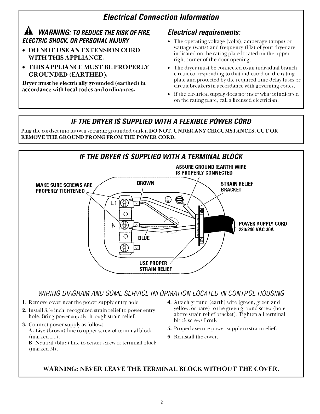
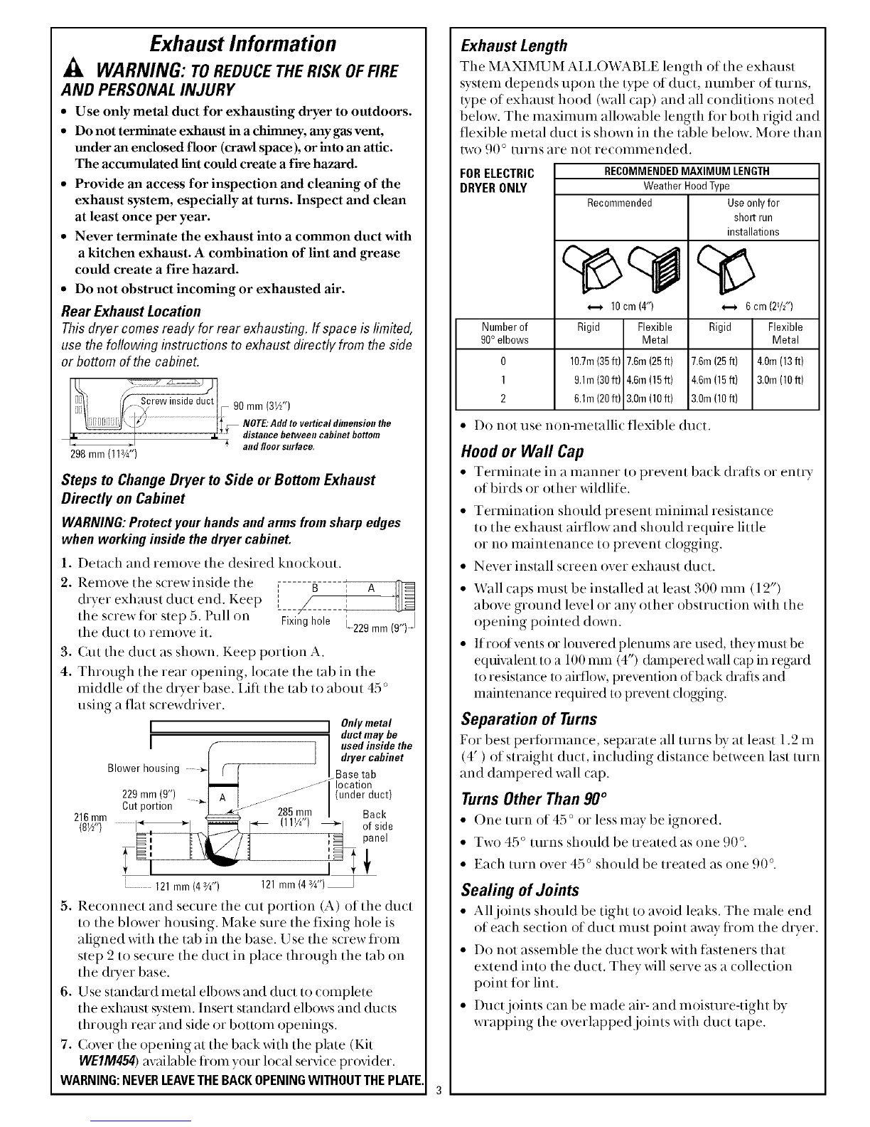
1. Detach and remove the desired knockout.
2. Remove the screwinside the ,, B A
dryer exhaust duct end. Keep i 1
the screw for step 5. Pull on Fixinghole L229 mm
the duct to remove it.
3. Cut the duct as shown. Keep portion A.
4. Through the rear opening, h)cate the tab in the
nfiddle of the (hTer base. Lift the tab to about 45 °
using a fiat s(rewdriver. Onlymetal
I;duct may be
I1Iused inside the
[ I dryer cabinet
Blower housing ........i%:
,29mm,9",J ,
Cut portion 285 rnm
216mm (11%")_1
(8V[') of side
121 mm(4aA") 121mm(4W')
5. Reconnect and secure the cut portion (A) of the duct
to the blower housing. Make sure the fixing hole is
aligned with the tab in the base. Use the s(iew flOln
step 2to secure the duct in place through the tab on
the &Ter base.
6. Use standard metal elbows and duct to complete
the exhaust system. Insert standard elbows and ducts
through rear and side or bottom openings.
7. (over the opening at the back with the plate (Kit
WEIM454)available flOln your h)cal serxfce prox4der.
WARNING:NEVERLEAVETHEBACKOPENINGWITHOUTTHEPLATE.
Exhaust Length
The MAXIMUM AIA_€)'v\LMH_Elength of the exhaust
system depends upon the type of duct, number of turns,
type of exhaust hood (wall cap) and all conditions noted
below. The maximum allowable length fin both rigid and
fexible metal duct is shown in the table below. More that
two 90 o turns are not recommended.
FORELECTRIC
DRYERONLY RECOMMENDEDMAXIMUM LENGTH
Weather HoodType
Recommended Use onlyfor
Numberof
90°elbows
0
1
2
• Do not use non-metallic flexible duct.
10cm(4")
Rigid Flexible
Metal
10.7m(35ft) 7.6m(25ft)
9.1m(30ft) 4,6m(15ft)
6.1m(20ft) 3.0m(10ft)
shortrun
installations
_--_ 6cm (2W')
Rigid Flexible
Metal
7.6m(25ft) 4.0m(13ft)
4.6m(15ft) 3.0m(10ft)
3.0m(10ft)
Hood or Wall Cap
• Terminate in a manner to prevent ba(k drafts or enu T
of birds or other wildlife.
Termii_ation should present mildmal resistan(e
to the exhaust airflow and should require little
or no maintenan(e to prevent (logging.
Never install s(reen over exhatlst (hi(l,
Wall caps must be installed at least 300 mm(12")
above ground level or any other obstruction with the
opening pointed down.
If root vents or louvered plenums are used, they must be
equivalent to a 100 mm (4") dampered wall cap in regard
to resistance to airflow, prevention of back drafts and
maintenance required to prevent clogging.
Separation of Turns
For best performance, separate all turns by at least 1.2 m
(4') of straight duct, including distance between last turn
and dampered wall cap.
Turns Other Than 90 °
• One turn of 45 ° or less may be ignored.
• Two 45° turns should be treated as()tie 90 °.
• Each turn over 45 ° should be treated as one 90 °.
Sealing of Joints
• All joints should be tight to avoid leaks. The male end
of each section of duct must point mvay fiom the dtTer,
• Do not assemble the duct work with tasteners that
extend into the duct, They will serve as a collection
point lot lint.
• Duct joints can be made air- and moisture-tight by
wrapping the overlapped joints with duct tape.