GE GFDS350GLWW User manual

WARNING RISK OF FIRE
• To reduce the risk of severe injury or death, follow all installation instructions.
• Clothes dryer installation must be performed by a qualied installer.
• Install the clothes dryer according to these instructions and in accordance with local
codes.
• California Safe Drinking Water and Toxic Enforcement Act
This act requires the governor of California to publish a list of substances known to the
state to cause cancer, birth defects or other reproductive harm and requires businesses
to warn customers of potential exposure to such substances. Gas appliances can
cause minor exposure to four of these substances, namely benzene, carbon monoxide,
formaldehyde and soot, caused primarily by the incomplete combustion of natural gas
or LP fuels. Properly adjusted dryers will minimize incomplete combustion. Exposure to
these substances can be minimized further by properly venting the dryer to the outdoors.
• This dryer must be exhausted to the outdoors.
• Use only rigid metal 4” diameter ductwork inside the dryer cabinet and use only UL
approved transition ducting between the dryer and the home duct.
• DO NOT install a clothes dryer with exible plastic ducting materials. If exible metal
(semirigid or foil-type) duct is installed, it must be UL listed and installed in accordance
with the instructions found in “Connecting The Dryer To House Vent” on page 5 of this
manual. Flexible venting materials are known to collapse, be easily crushed, and trap
lint. These conditions will obstruct dryer airow and increase the risk of re.
• Do not install or store this appliance in any location where it could be exposed to
water and or weather.
• Save these instructions. (Installers: Be sure to leave these instructions with the
customer).
IN THE COMMONWEALTH OF MASSACHUSETTS
• This product must be installed by a licensed plumber or gas tter.
• When using ball-type gas shut-off valves, they shall be the T-handle type.
• A flexible gas connector, when used, most not exceed 3 feet.
Installation
Instructions
Gas Dryer
10
Questions on Installation? Call: 1-800-GECARES (US) or 1-800-561-3344 (Canada)
or Visit our Web site at: www.GEAppliances.com (US)
BEFORE YOU BEGIN
Read these instructions
completely and carefully.
•IMPORTANT- Save these
instructions for local inspector’s
use.
•IMPORTANT- Observe all
governing codes and ordinances.
• Note to Installer - Be sure to
leave these instructions with the
customer.
• Note to Customer - Keep
these instructions with your
Use and Care Book for future
reference.
• Before the old dryer is removed
from service or discarded,
remove the dryer door.
• Service information and the
wiring diagram are located in
the control console.
• Do not allow children on or in
the appliance. Close supervision
of children is necessary when
the appliance is used near
children.
• Install the dryer where the
temperature is above 50°F for
satisfactory operation of the
dryer control system.
31-16630-1 03-11 GE
234D1052P004
Step 1 Verify your gas installation (see section 2).
Step 2 Prepare the area and exhaust for installation of new dryer
(see section 1).
Step 3 Check and ensure the existing external exhaust is clean (see
section 1) and meets attached installation specications (see
section 6).
Step 4 Remove the foam shipping pads (see section 1).
Step 5 Move the dryer to the desired location.
Step 6 Level your dryer (see section 8).
Step 7 Connect the gas supply (see section 3) and check for leaks
(see section 4).
Step 8 Connect the external exhaust (see section 7).
Step 9 Connect the power supply (see section 5).
Step 10
Check the operation of the power supply, gas connections,
and venting.
Step 11
Place the owners manual and the installation instructions in a
location where they will be noticed by the owner.
For alcove or closet installation, see section 9.
For bathroom or bedroom installation, see section 10.
For mobile or manufactured home, see section 11.
For side or bottom exhaust, see section 12.
LEVEL
8" PIPE WRENCH
10" ADJUSTABLE WRENCHES
(x2)
TOOLS YOU WILL NEED
SLIP JOINT PLIERS FLAT BLADE SCREWDRIVER
MATERIALS YOU WILL NEED
GLOVES
SAFETY
GLASSES
4" DUCT
CLAMPS (2)
OR
4" SPRING
CLAMPS (2)
EXHAUST
HOOD
4" DIA. METAL
ELBOW
4" DIA. FLEXIBLE METAL (SEMI-RIGID)
UL LISTED TRANSITION DUCT
(IF NEEDED)
KIT WX08X10077 (INCLUDES 2 ELBOWS)
4" DIA. METAL DUCT
(RECOMMENDED)
4" DIA. FLEXIBLE METAL (FOIL TYPE)
UL LISTED TRANSITION DUCT
(IF NEEDED.)
DUCT TAPE
SOAP SOLUTION
FOR LEAK DETECTION
PIPE
COMPOUND
FLEXIBLE GAS LINE CONNECTOR

Installation Instructions
2
Minimum Clearance Other Than Alcove or Closet Installation
Minimum clearance to combustible surfaces and for air opening are: 0 in. clearance both sides, 1 in. front 3 in. rear.
Consideration must be given to provide adequate clearance for installation and service.
1 PREPARING FOR INSTALLATION
OF NEW DRYER
TIP: Install your dryer before installing your washer.
This will allow better access when installing dryer exhaust.
DISCONNECTING GAS
WARNING - NEVER REUSE OLD
FLEXIBLE CONNECTORS.
The use of old exible connectors can cause leaks
and personal injury. Always use new exible
connectors when installing gas appliances.
REMOVING LINT FROM WALL EXHAUST
OPENING
• Remove and discard existing plastic or metal foil transition
duct and replace with UL listed transition duct.
INTERNAL DUCT
OPENING CHECK THAT EXHAUSE
HOOD DAMPER OPENS
AND CLOSES FREELY.
WALL
TILT THE DRYER SIDEWAYS
AND REMOVE THE FOAM
SHIPPING PADS BY
PULLING AT THE SIDES
AND BREAKING THEM
AWAY FROM THE DRYER
LEGS. BE SURE TO
REMOVE ALL OF THE
FOAM PIECES AROUND
THE LEGS.
TURN GAS
SHUT-OFF
VALVE TO THE
OFF POSITION.
DISCONNECT AND DISCARD OLD
FLEXIBLE GAS CONNECTOR AND
OLD DUCTING MATERIAL.
REPLACE WITH NEW CSA(AGA)
APPROVED FLEXIBLE GAS LINE
CONNECTOR AND UL APPROVED
TRANSITION DUCT.
2 GAS REQUIREMENTS
WARNING
• Installation must conform to local codes and
ordinances,or in their absence, the NATIONAL FUEL GAS
CODE,ANSI Z223.
• This gas dryer is equipped with a Valve & Burner Assem-
bly for use only with natural gas. Using conversion kit
WE25X0217, your local service organization can convert
this dryer for use with propane (LP) gas. ALL CONVER-
SIONS MUST BE MADE BY PROPERLY TRAINED AND QUALI-
FIED PERSONNEL AND IN ACCORDANCE WITH LOCAL
CODES AND ORDINANCE REQUIREMENTS.
• The dryer must be disconnected from the gas supply
piping system during any pressure testing of that sys-
tem at a test pressure in excess of 0.5 PSI (3.4 KPa).
• The dryer must be isolated from the gas supply piping
system by closing the equipment shut-o valve during
any pressure testing of the gas supply piping of test
pressure equal to or less than 0.5 PSI (3.4 KPa).
DRYER GAS SUPPLY CONNECTION
GAS SUPPLY
• A 1/8 in. National Pipe Taper thread plugged tapping,
accessible for test gauge connection, must be installed
immediately upstream of the gas supply connection to
the dryer. Contact your local gas utility should you have
questions on the installation of the plugged tapping.
• Supply line is to be 1/2 in. rigid pipe and equipped with
an accessible shut-o within 6 ft. of, and in the same
room with the dryer.
• Use pipe thread sealer compound appropriate for natu-
ral or LP gas or use Teon tape.
• Connect exible metal connector to dryer and gas sup-
ply.
• Open shut-o valve.
• You must use with this dryer a exible metal connector
(listed connector ANSI Z21.24 / CSA 6.10). The length of
the connect shall not exceed 3 ft.
2"
2-5/8" 3/8" NPT MALE THREAD GAS SUPPLY
NOTE: Add to vertical dimension
the distance between cabinet
bottom to floor.

Installation Instructions
3
3RECONNECTING GAS
NEW METAL
FLEXIBLE GAS
LINE CONNECTOR
ADAPTER
ELBOW
ITEMS NOT SUPPLIED
ADAPTER
SHUT-OFF
VALVE
PIPE SIZE
AT LEAST 1/2"
1/8" NPT PIPE
PLUG FOR
CHECKING GAS
INLET PRESSURE
3/8" NPT
Listed connector ANSI Z21.24 / CSA 6.10
NOTE: The connector and ttings are designed for use
only on the original installation and are not to be reused
for another appliance or at another location. Keep are
end of adaptor free of grease, oil and thread sealant.
CAUTION: Use adaptors as shown. Connector nuts
must not be connected directly to pipe threads.
APPLY PIPE COMPOUND
TO THE ADAPTER AND
DRYER GAS INLET.
Tighten the flexible
gas line using two
adjustable wrenches.
APPLY PIPE COMPOUND
TO ALL MALE THREADS.
Tighten all connections using two adjustable
wrenches. Do not overtorque gas connections!
Check all connections for leaks with soapy solution or
equivalent. Apply soap solution. Leak test solution must
not contain ammonia which could cause damage to the
brass ttings. If leaks are found, close valve, retighten the
joint, and repeat the soap test.
4LEAK TEST
WARNING - NEVER USE AN OPEN
FLAME TO TEST FOR GAS LEAKS.
OPEN
GAS VALVE.

Installation Instructions
4
6 EXHAUST INFORMATION
EXHAUST SYSTEM CHECK LIST
HOOD OR WALL CAP
• Terminate in a manner to prevent back drafts or entry of
birds or other wildlife.
• Termination should present minimal resistance to
the exhaust air ow and should require little or no
maintenance to prevent clogging.
• Never install a screen in or over the exhaust duct. This
could cause lint build up.
• Wall caps must be installed at least 12 in. above ground
level or any other obstruction with the opening pointed
down.
SEPARATION OF TURNS
For best performance, separate all turns by at least 4 ft.
of straight duct, including distance between last turn and
exhaust hood.
TURNS OTHER THAN 90º
• One turn of 45º or less may be ignored.
• Two 45º turns should be treated as one 90º turn.
• Each turn over 45º should be treated as one 90º turn.
WARNING - IN CANADA AND IN THE
UNITED STATES, THE REQUIRED EXHAUST
DUCT DIAMETER IS 4 in (102mm). DO NOT
USE DUCT LONGER THAN SPECIFIED IN THE
EXHAUST LENGTH TABLE.
Using exhaust longer than specied length will:
• Increase the drying times and the energy cost.
• Reduce the dryer life.
• Accumulate lint, creating a potential re hazard.
The correct exhaust installation is YOUR
RESPONSIBILITY. Problems due to incorrect
installation are not covered by the warranty.
Remove and discard existing plastic or metal foil
transition duct and replace with UL listed transition duct.
The MAXIMUM ALLOWABLE duct length and number of
bends of the exhaust system depends upon the type of
duct, number of turns, the type of exhaust hood (wall
cap), and all conditions noted below. The maximum duct
length for rigid metal duct is shown in the table below.
EXHAUST LENGTH
4" DIA.
4"
4" DIA.
Exhaust Hood Types
.No of 90º
Elbows Rigid
Metal
90 Feet
60 Feet
45 Feet
35 Feet
25 Feet
0
1
2
3
4
RECCOMMENDED MAX. LENGTH
5ELECTRICAL CONNECTION INFORMATION
WARNING - TO REDUCE THE RISK
OF FIRE, ELECTRICAL SHOCK, AND
PERSONAL INJURY:
• DO NOT USE AN EXTENSION CORD
OR AN ADAPTER PLUG WITH THIS
APPLIANCE.
Dryer must be electrically grounded in accordance
with local codes and ordinances, or in the absence
of local codes, in accordance with the NATIONAL
ELECTRICAL CODE, ANSI/NFPA NO. 70.
ELECTRICAL REQUIREMENTS
This appliance must be supplied with 120V, 60Hz, and
connected to a properly grounded branch circuit, pro-
tected by a 15- or 20-amp circuit breaker or time delay
fuse. If electrical supply provided does not meet the
above specications, it is recommended that a licensed
electrician install an approved outlet.
WARNING - THIS DRYER IS
EQUIPPED WITH A THREE-PRONG
(GROUNDING) PLUG FOR YOUR PROTEC-
TION AGAINST SHOCK HAZARD AND
SHOULD BE PLUGGED DIRECTLY INTO A
PROPERLY GROUNDED THREE-PRONG
RECEPTACLE. DO NOT CUT OR REMOVE
THE GROUNDING PRONG FROM THIS
PLUG.
IF LOCAL CODES PERMIT,
AN EXTERNAL GROUND WIRE
(NOT PROVIDED), WHICH MEETS
LOCAL CODES, MAY BE ADDED
BY ATTACHING TO THE GREEN
GROUND SCREW ON THE REAR
OF THE DRYER, AND TO A GROUNDED
METAL COLD WATER PIPE OR OTHER
ESTABLISHED GROUND.
ENSURE PROPER GROUND EXISTS BEFORE USE

Installation Instructions
5
SEALING OF JOINTS
• All joints should be tight to avoid leaks. The male end of
each section of duct must point away from the dryer.
• The duct shall not be assembled with screws or other
fastening means that extend into the duct and catch lint.
• Duct joints can be made air and moisture-tight by
wrapping the overlapped joints with duct tape.
• Horizontal runs should slope down toward the outdoors
1/2 inch per foot.
INSULATION
Duct work that runs through an unheated area or is
near air conditioning should be insulated to reduce
condensation and lint build-up.
7 EXHAUST CONNECTION
THIS DRYER COMES READY FOR REAR
EXHAUSTING. IF SPACE IS LIMITED, USE
THE INSTRUCTIONS IN SECTION 12 TO
EXHAUST DIRECTLY FROM THE SIDES OR
BOTTOM OF THE CABINET.
WARNING - TO REDUCE THE RISK
OF FIRE OR PERSONAL INJURY:
•
This clothes dryer must be exhausted to the outdoors.
• Use only 4” rigid metal ducting for the home exhaust
duct.
• Use only 4” rigid metal or UL-listed exible metal (semi-
rigid or foil-type) duct to connect the dryer to the home
exhaust duct. It must be installed in accordance with
the instructions found in “Connecting the Dryer to
House Vent” on pages 5-6 of this manual.
• Do not terminate exhaust in a chimney, a wall, a ceiling,
gas vent, crawl space, attic, under an enclosed oor,
or in any other concealed space of a building. The
accumulated lint could create a re hazard.
• Never terminate the exhaust into a common duct with
a kitchen exhaust system. A combination of grease and
lint creates a potential re hazard.
• Do not use duct longer than specied in the exhaust
length table. Longer ducts can accumulate lint, creating
a potential re hazard.
• Never install a screen in or over the exhaust duct. This
will cause lint to accumulate, creating a potential re
hazard.
• Do not assemble ductwork with any fasteners that
extend into the duct. These fasteners can accumulate
lint, creating a potential re hazard.
• Do not obstruct incoming or exhausted air.
•
Provide an access for inspection and cleaning of the
exhaust system, especially at turns and joints. Exhaust
system shall be inspected and cleaned at least once a year.
CONNECTING THE DRYER TO HOUSE VENT
RIGID METAL TRANSITION DUCT
• For best drying performance, a rigid metal transition duct
is recommended.
• Rigid metal transition ducts reduce the risk of crushing and
kinking.
UL-LISTED FLEXIBLE METAL (SEMI-RIGID) TRANSITION
DUCT
• If rigid metal duct cannot be used, then UL-listed exible
metal (semi-rigid) ducting can be used (Kit WX08X10077).
• Never install exible metal duct in walls, ceilings, oors or
other enclosed spaces.
• Total length of exible metal duct should not exceed 8 feet
(2.4m).
DUCT TAPE OR
DUCT CLAMP
DUCT TAPE OR
DUCT CLAMP
4" METAL DUCT CUT
TO PROPER LENGTH
EXTERNAL DUCT
OPENING
For straight line installation, connect
the dryer exhaust to the external
exhaust hood using duct tape or
clamp.
NOTE: WE STRONGLY RECOMMEND SOLID
METAL EXHAUST DUCTING. HOWEVER, IF
FLEXIBLE DUCTING IS USED IT MUST BE
UL-LISTED METAL, NOT PLASTIC.
STANDARD REAR EXHAUST
(Vented at oor level)
STANDARD REAR EXHAUST
(Vented above oor level)
NOTE: ELBOWS WILL PREVENT DUCT
KINKING AND COLLAPSING.
ELBOW HIGHLY
RECOMMENDED
ELBOW HIGHLY
RECOMMENDED
RECOMMENDED
CONFIGURATION
TO MINIMIZE
EXHAUST
BLOCKAGE.

Installation Instructions
6
LEVELING AND STABILIZING YOUR
DRYER
Stand the dryer upright near the nal location and adjust
the 4 leveling legs, at the corners, to ensure that the dryer
is level from side to side and front to rear.
9 ALCOVE OR CLOSET INSTALLATION
• If your dryer is approved for installation in an alcove or
closet, it will be stated on a label on the dryer back.
• The dryer MUST be vented to the outdoors. See the
EXHAUST INFORMATION section 6.
• Minimum clearance between dryer cabinet and adjacent
walls or other surfaces is:
0 in. either side
3 in. front
4 in. rear
• Minimum vertical space from oor to overhead cabinets,
ceiling, etc. is 52 in.
• Closet doors must be louvered or otherwise ventilated
and must contain a minimum of 60 sq. in. of open area
equally distributed. If the closet contains both a washer
and a dryer, doors must contain a minimum of 120 sq. in.
of open area equally distributed.
• The closet should be vented to the outdoors to prevent
gas pocketing in case of a gas leak in the supply line.
• No other fuel-burning appliance shall be installed in the
same closet with the dryer.
NOTE: WHEN THE EXHAUST DUCT IS LOCATED AT THE
REAR OF THE DRYER, MINIMUM CLEARANCE FROM THE
WALL IS 5.5 in.
DO
ELBOW
REQUIRED
ELBOWS
REQUIRED
DON’T
DO NOT USE
EXCESSIVE
EXHAUST
LENGTH
DO NOT
CRUSH
FLEXIBLE
EXHAUST
AGAINST
WALL
DO NOT
SIT DRYER
ON FLEXIBLE
EXHAUST
8
LEVEL
SIDE-TO-SIDE
4 LEVELING
LEGS
LEVEL
FRONT-TO-BACK
Stand the dryer upright near the final location and adjust
the 4 leveling legs, at the corners, to ensure that the dryer
is level from side to side and front to rear.
• For many applications, installing elbows at both the dryer
and the wall is highly recommended (see illustrations
below). Elbows allow the dryer to sit close to the wall
without kinking and or crushing the transition duct,
maximizing drying performance.
• Avoid resting the duct on sharp objects.
UL-LISTED FLEXIBLE METAL (FOIL-TYPE) TRANSITION DUCT
• In special installations, it may be necessary to connect
the dryer to the house vent using a exible metal (foil-
type) duct. A UL-listed exible metal (foil-type) duct may
be used ONLY in installations where rigid metal or exible
metal (semi-rigid) ducting cannot be used AND where a 4”
diameter can be maintained throughout the entire length
of the transition duct.
•
In Canada and the United States, only the exible metal
(foil-type) ducts that comply with the “Outline for Clothes
Dryer Transition Duct Subject 2158A” shall be used.
• Never install exible metal duct in walls, ceilings, oors or
other enclosed spaces.
• Total length of exible metal duct should not exceed 8 feet
(2.4m).
• Avoid resting the duct on sharp objects.
For best drying performance:
1. Slide one end of the duct over the clothes dryer outlet pipe.
2. Secure the duct with a clamp.
3. With the dryer in its permanent position, extend the duct
to its full length. Allow 2” of duct to overlap the exhaust pipe.
Cut o and remove excess duct. Keep the duct as straight
as possible for maximum airow.
4. Secure the duct to the exhaust pipe with the other clamp.

Installation Instructions
7
13 DRYER EXHAUST TO LEFT OR BOTTOM
CABINET
WARNING - PROTECT YOUR
HANDS AND ARMS FROM SHARP EDGES
WHEN WORKING INSIDE CABINET.
Detach and remove the bottom, right or left side knockout
as desired. Remove the screw inside the dryer exhaust duct
and save. Pull the duct out of the dryer.
REMOVE
SCREW
AND SAVE.
REMOVE
DESIRED
KNOCKOUT
(ONE ONLY).
Through the rear opening, locate the tab in the middle of
the appliance base. Lift the tab to about 45º using a flat
blade screwdriver.
BEND TAB
UP 45 o
RIGHT OR
LEFT SIDE
EXHAUST
PORTION "A"
FIXING
HOLE
10
BATHROOM OR BEDROOM INSTALLATION
• The dryer MUST be vented to the outdoors. See EXHAUST
INFORMATION section 6.
• The installation must conform with local codes or, in the
absence of local codes, with the NATIONAL ELECTRICAL
CODE, ANSI/NFPA NO. 70.
MOBILE OR MANUFACTURED HOME
INSTALLATION
• Installation must conform to the MANUFACTURED HOME
CONSTRUCTION & SAFETY STANDARD, TITLE 24, PART
32-80 or, when such standard is not applicable, with
AMERICAN NATIONAL STANDARD FOR MOBILE HOME,
ANSI/NFPA NO. 501B.
• The dryer MUST be vented to the outdoors with the
termination securely fastened to the mobile home
structure. (See EXHAUST INFORMATION section 6).
• The vent MUST NOT be terminated beneath a mobile or
manufactured home.
• The vent duct material MUST BE METAL.
• KIT 14-D346-33 MUST be used to attach the dryer
securely to the structure.
• The vent MUST NOT be connected to any other duct,
vent, or chimney.
•
Do not use sheet metal screws or other fastening devices
which extend into the interior of the exhaust vent.
• Provide an opening with a free area of at least 25 sq. in.
for introduction of outside air into the dryer room.
11
TAB LOCATION
ADDING NEW DUCT
Detach and remove the bottom or left side knockout as
desired. Remove the screw inside the dryer exhaust duct
and save. Pull the duct out of the dryer. Protect sharp edges
around the knockout and exhaust opening with the tape.
Cut the duct as shown and keep portion A.
13 1/2"
AB
FIXING HOLE
(13 1/4” for bottom venting)
Reconnect the cut portion (A) of the duct to the blower
housing. Make sure that the xing hole is aligned with the
tab in the base. Use the screw saved previously to secure
the duct in place through the tab on the appliance base.
12
• Dryers installed in residential garages must be elevated
18 inches (46cm) above the oor.

Installation Instructions
8
ADDING ELBOW AND DUCT FOR
EXHAUST TO LEFT OR RIGHT SIDE OF
CABINET
• Preassemble 4” elbow with 4” duct. Wrap duct tape
around joint.
•
Insert duct assembly, elbow rst, through the side
opening and connect the elbow to the dryer internal duct.
CAUTION: Be sure not to pull or damage the
electrical wires inside the dryer when inserting the duct.
• Apply duct tape as shown on the joint between the dryer
internal duct and the elbow.
ADDING ELBOW FOR EXHAUST
THROUGH BOTTOM OF CABINET
• Insert the elbow through the rear opening and connect it
to the dryer internal duct.
• Apply duct tape on the joint between the dryer internal
duct and elbow, as shown above.
DUCT
TAPE
CAUTION:
Use 4” rigid metal ducting only
inside the dryer. Internal duct
joints must be secured with
tape, otherwise they may sepa-
rate and cause a safety hazard.
ADDING COVER PLATE TO REAR OF
CABINET
Connect standard metal elbows and ducts to complete the
exhaust system. Cover back opening with a plate (Kit
WE1M454) available from your local service provider.
Place dryer in nal location.
CAUTION:
Internal duct joints must be secured with tape,
otherwise they may separate and cause a
safety hazard.
PL ATE
(KIT WE1M454)
WARNING-NEVER LEAVE THE
BACK OPENING WITHOUT THE PLATE.
TO REGISTER YOUR DRYER
CALL TOLL-FREE
1-888-269-1192
Prompt registration conrms your right to protection under
the terms of your warranty.
www.GEAppliances.com (US)
For Questions on Installation, Call: 1-800-GECARES (US) or
1-800-361-3400 (Canada).
DUCT
TAPE

ADVERTENCIA RIESGO DE INCENDIO
• Para reducir el riesgo de una lesión grave o de muerte, cumpla con todas las
instrucciones de instalación.
• La instalación de la secadora debe efectuarla un instalador calicado.
• Instale la secadora de ropa de acuerdo con estas instrucciones y en cumplimiento
con los códigos locales.
• Ley de California para el agua potable y los tóxicos
Esta ley exige que el Gobernador de California publique una lista de sustancias que según
el estado provoquen cáncer, defectos congénitos u otros daños reproductivos, y exige a las
empresas que adviertan a los clientes sobre la exposición potencial a dichas sustancias.
Los aparatos a gas pueden provocar una exposición mínima a estas sustancias, a saber,
benceno, monóxido de carbono, formaldehído y hollín, generados principalmente por la
combustión incompleta de gas natural o combustibles LP. Si se ajustan bien las secadoras,
la combustión incompleta se verá minimizada. La exposición a estas sustancias puede
minimizarse aún más mediante una ventilación adecuada hacia el exterior.
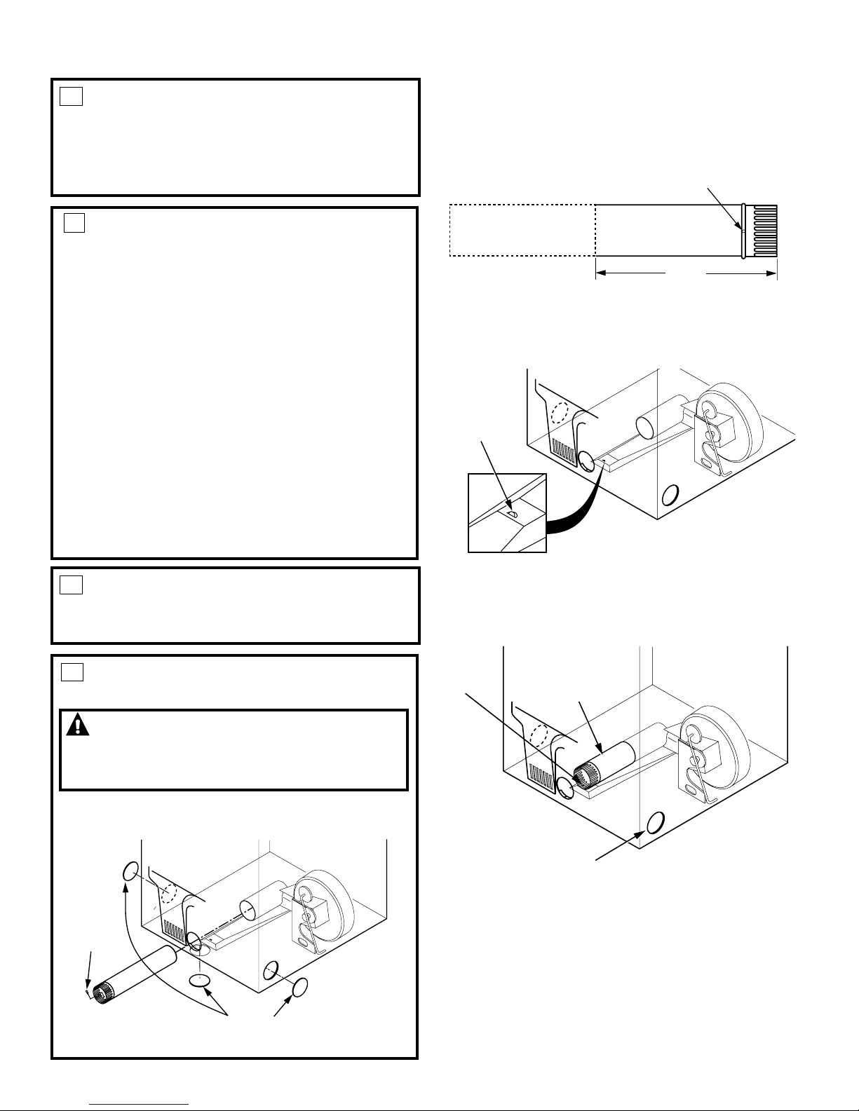
• Esta secadora debe tener una salida al exterior.
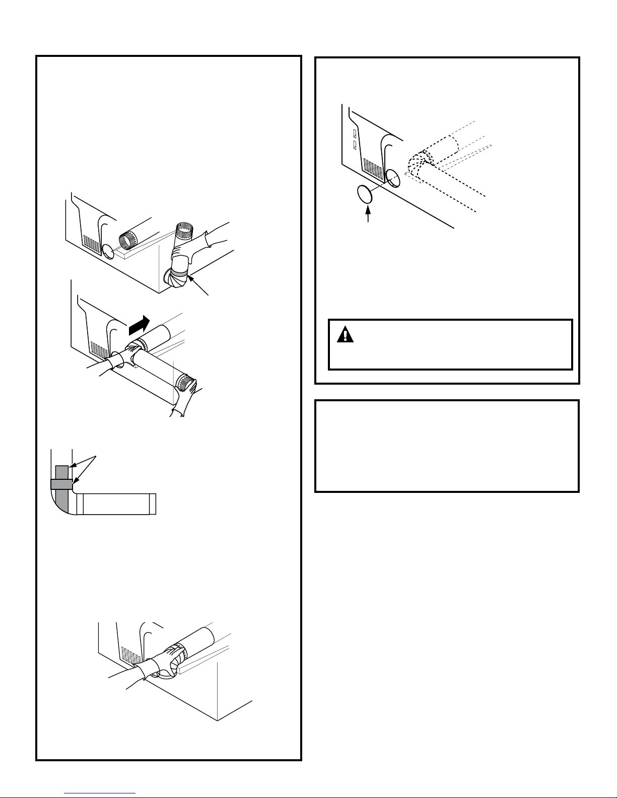
• Utilice sólo un conducto rígido de metal de un diámetro de 4” dentro del gabinete de la secadora
y use sólo un conducto de transición aprobado por UL entre la secadora y el conducto doméstico.
•
NO instale una secadora de ropa con conductos de plástico exible. Si se instala un
conducto exible de metal (semi rígido o de tipo papel de aluminio), debe estar aprobado
por UL e instalarse de acuerdo con las instrucciones de “Cómo conectar la secadora a la
ventilación doméstica” de la página 5 de este manual. Los materiales de ventilación exibles
a menudo se desploman, se aplastan y atrapan pelusas. Estas condiciones obstruyen la
corriente de aire de la secadora e incrementan el riesgo de incendio.
• No instale o almacene este aparato en un lugar donde se vea expuesto al agua y/o
a las inclemencias del tiempo.
• Guarde estas instrucciones. (Instaladores: Asegúrese de dejar estas instrucciones
al consumidor).
EN EL ESTADO DE MASSACHUSETTS
• Este producto debe instalarlo un plomero o un gastero matriculado.
• Cuando use válvulas esféricas de cierre de gas, deberán ser del tipo de manija en T.
• Si se usa una conexión exible para gas, ésta no debe superar los 3 pies.
Instrucciones
de instalación
Secadora a gas
10
¿Preguntas sobre la instalación? Llame al: 1-800-GECARES (EE.UU.) o 1-800-561-3344 (Canadá)
o visite nuestro sitio Web en: www.GEAppliances.com (EE.UU.)
ANTES DE COMENZAR
Lea estas instrucciones por
completo y con detenimiento.
•IMPORTANTE - Guarde
estas instrucciones para el uso de
inspectores locales.
•IMPORTANTE - Siga todos
los códigos y ordenanzas vigentes.
• Nota al instalador - Asegúrese
de dejar estas instrucciones con el
consumidor.
• Nota al consumidor - Mantenga
estas instrucciones con el Manual de
uso y cuidados para referencia futura.
• Antes de que la secadora antigua
sea retirada del servicio o elimi-
nada, quítele la puerta.
•
La información sobre reparaciones
y el diagrama del cableado se en-
cuentran en la consola de control.
• No permita que niños se suban
o se metan dentro del aparato. Se
requiere una supervisión estricta
cuando el aparato es utilizado
cerca de niños.
• Instale la secadora en lugares
donde la temperatura sea mayor
a 50°F para un funcionamiento
satisfactorio del sistema de control
de la secadora.
31-16630-1 03-11 GE
234D1052P004
Paso 1 Verique su instalación de gas (ver sección 2).
Paso 2 Prepare el área y la salida para la instalación de la nueva
secadora (ver sección 1).
Paso 3 Verique y asegúrese de que la salida al exterior existente
esté limpia (ver sección 1) y que cumpla con las especica-
ciones de instalación incluidas (ver sección 6).
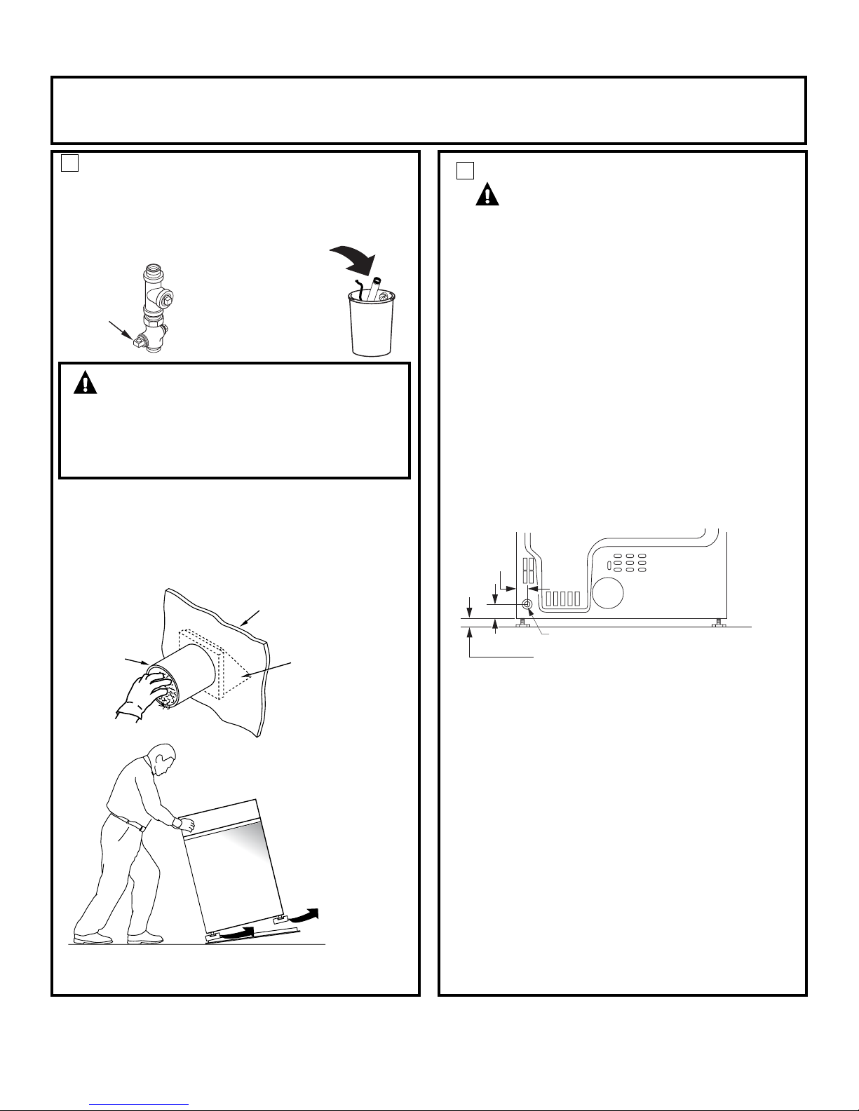
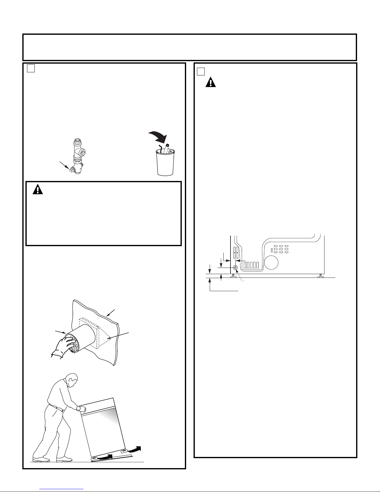
Paso 4 Quite las almohadillas de espuma para envío (ver sección 1).
Paso 5 Desplace la secadora a la ubicación deseada.
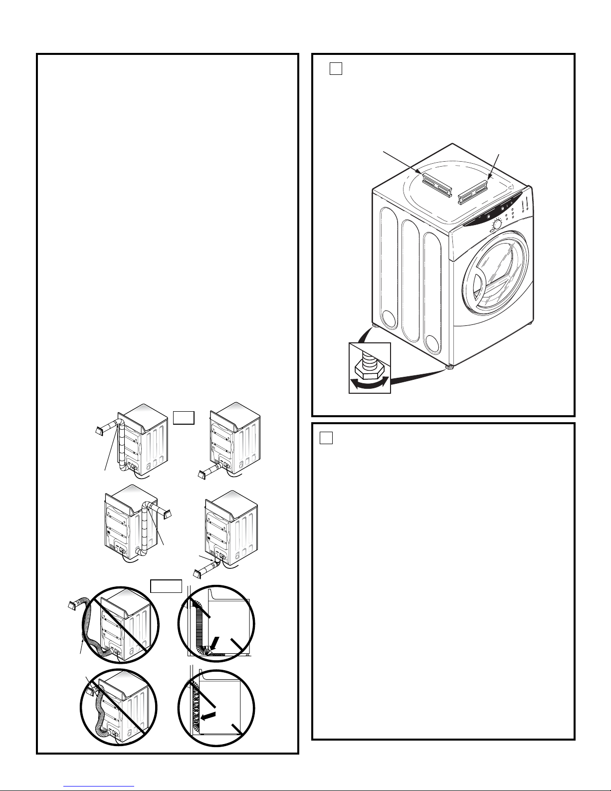
Paso 6 Nivele su secadora (ver sección 8).
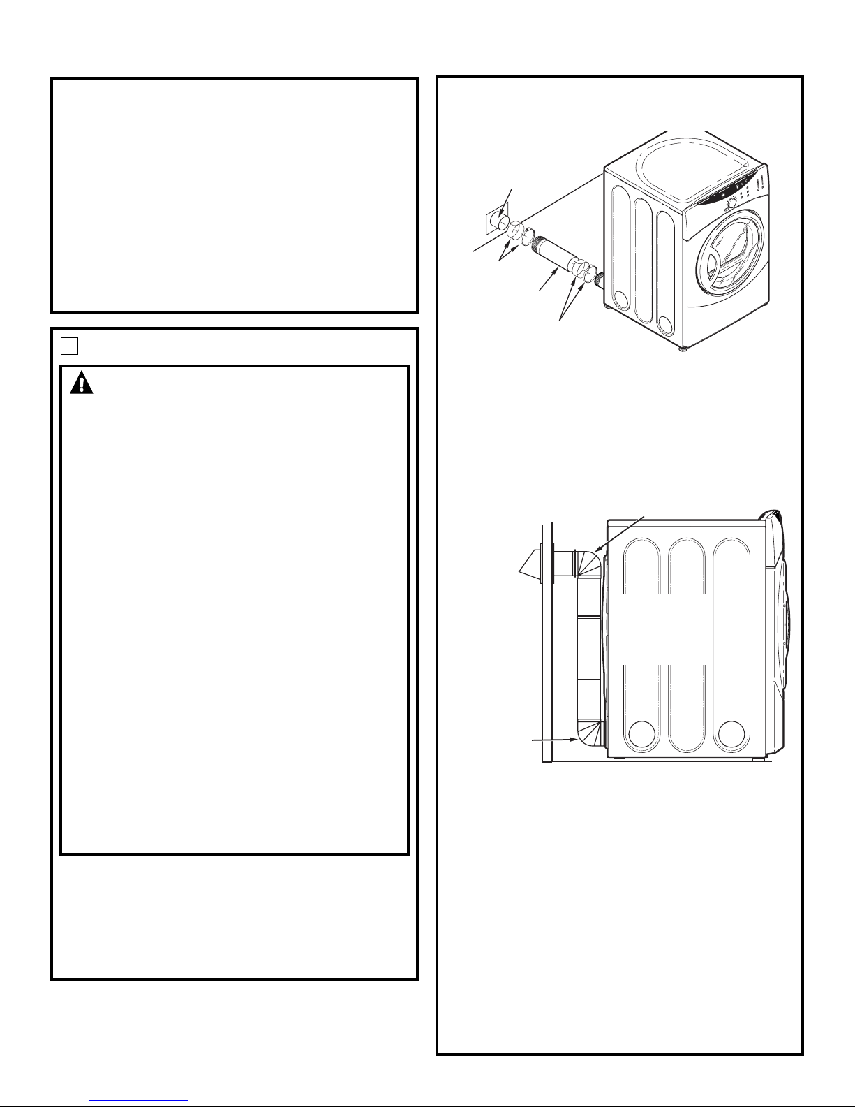
Paso 7 Conecte el suministro de gas (ver sección 3) y controle la pres-
encia de pérdidas (ver sección 4).
Paso 8 Conecte la salida al exterior (ver sección 7).
Paso 9 Conecte el suministro de energía (ver sección 5).
Paso 10 Verique el funcionamiento del suministro de energía, las
conexiones de gas y la ventilación.
Paso 11 Coloque el manual del propietario y las instrucciones de
instalación en un lugar de fácil acceso para el propietario.
Para instalación en nicho o closet, ver sección 9.
Para instalación en baños o dormitorios, ver sección 10.
Para casas móviles o prefabricadas, ver sección 11.
Para salidas laterales o por la parte inferior, ver sección 12.
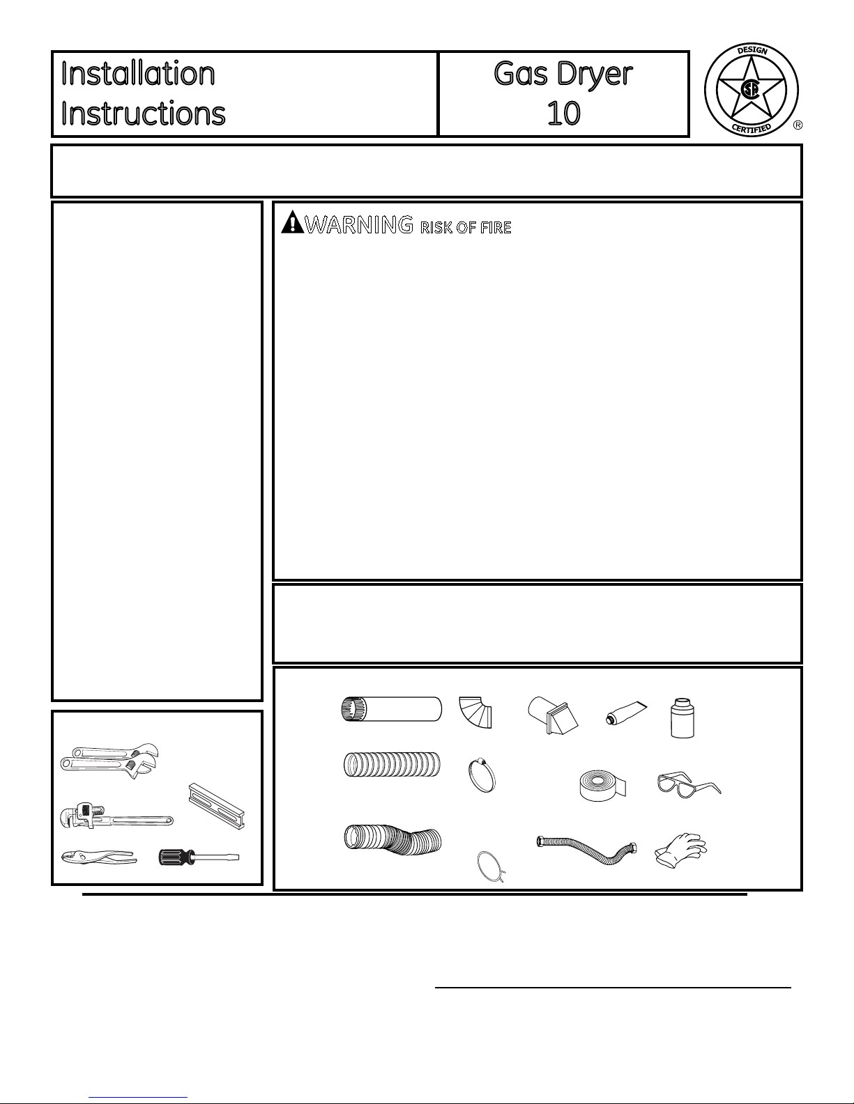
MATERIALES NECESARIOS
GUANTES
GAFAS
DE SEGURIDAD KIT DE CABLE
DE ENERGÍA
DE LA SECADORA
(NO PROVISTA CON
ABRAZADERAS
DE CONDUCTO DE 4" (2)
O
ABRAZADERAS
DE RESORTE DE 4" (2)
CAMPANA
DE SALIDA
ALIVIO DE TENSIÓN
DE ¾” RECONOCIDO
POR UL
CODO DE METAL
DE 4” DE DIÁ.
CONDUCTO DE TRANSICIÓN DE METAL
FLEXIBLE (SEMI RÍGIDO) DE 4” DE DIÁ.
APROBADO POR UL (SI FUERA NECESARIO)
KIT WX08X10077 (INCLUYE 2 CODOS)
CONDUCTO DE METAL DE 4” DE DIÁ
(RECOMENDADO)
CONDUCTO DE TRANSICIÓN DE METAL
FLEXIBLE (TIPO PAPEL DE ALUMINIO) DE 4” DE DIÁ.
APROBADO POR UL (SI FUERA NECESARIO)
CINTA ADHESIVA
CLASIFICADO POR
UL 120/240V, 30A
CON 3 O 4 CLAVIJAS.
IDENTIFIQUE EL TIPO
DE ENCHUFE SEGÚN
EL TOMACORRIENTE
DE LA VIVIENDA ANTES
DE COMPRAR EL CABLE.
LA SECADORA)
PLACA DE CUBIERTA DE 4”
(SI FUERA NECESARIO)
(KIT WE1M454)
NIVEL
LLAVE PARA TUBOS DE 8”
LLAVES AJUSTABLES DE 10”
(x2)
HERRAMIENTAS NECESARIAS
ALICATES DE
JUNTA DESLIZANTE DESTORNILLADOR PLANO

Instrucciones de instalación
2
Espacio mínimo diferente a instalación en nichos o closets.
Los espacios libres mínimos respecto de supercies combustibles y de aberturas de aire son: Espacio de 0 pulg. a ambos lados, 1 pulg. en el
frente y 3 pulg. en la parte trasera. Debe tenerse en cuenta un espacio libre adecuado para un funcionamiento y reparación correctos.
1 PREPARACIÓN PARA LA INSTALACIÓN
DE UNA SECADORA NUEVA
CONSEJO: Instale su secadora antes de instalar la lava-
dora. Esto permitirá un mejor acceso cuando instale la
salida de la secadora.
CÓMO DESCONECTAR EL GAS
ADVERTENCIA - NUNCA VUELVA A
USAR CONECTORES FLEXIBLES GAS-
TADOS.
El uso de conectores exibles usados puede provocar
pérdidas de gas y lesiones personales. Siempre utilice
conectores exibles nuevos cuando instale aparatos
de gas.
CÓMO QUITAR PELUSA DE LA ABERTURA
DE LA SALIDA DE LA PARED
• Quite y descarte el conducto de transición existente de
plástico o de papel de aluminio y coloque un conducto de
transición aprobado por UL.
ABERTURA DE
CONDUCTO INTERNA
PARED
VERIFIQUE QUE
EL REGULADOR
DE TIRO DE LA CAMPANA
DE SALIDA SE ABRA
Y CIERRE LIBREMENTE
INCLINE LA SECADORA
DE COSTADO Y QUITE
LAS ALMOHADILLAS
DE ESPUMA PARA ENVÍO
TOMÁNDOLAS DE LOS
COSTADOS Y
ARRANCÁNDOLAS DE LAS
PATAS DE LA SECADORA.
ASEGÚRESE DE QUITAR
TODAS LAS PIEZAS
DE ESPUMA UBICADAS
ALREDEDOR DE LAS PATAS.
GIRE LA VÁLVULA
DE CIERRE DE GAS
A LA POSICIÓN OFF
(APAGADO)
DESCONECTE Y ELIMINE
EL CONECTOR DE GAS
FLEXIBLE ANTIGUO Y
LOS CONDUCTOS VIEJOS.
REEMPLÁCELOS CON
UN NUEVO CONECTOR
DE LÍNEA DE GAS FLEXIBLE
APROBADO POR CSA (AGA) Y
UN CONDUCTO DE TRANSICIÓN
APROBADO POR UL.
2 REQUERIMIENTOS DE GAS
ADVERTENCIA
• La instalación debe cumplir con códigos o ordenanzas
locales, o si no las hubiera, con el CÓDIGO NACIONAL DE
GAS, ANSI Z223.
• Esta secadora a gas está equipada con un montaje de
válvula y quemador para utilizar sólo con gas natural.
Mediante el kit de conversión WE25X0217, la organización
de atención local puede convertir esta secadora para su
uso con gas propano (LP). TODAS LAS CONVERSIONES
DEBEN LLEVARLAS A CABO PERSONAL CAPACITADO Y
CALIFICADO EN CUMPLIMIENTO CON CÓDIGOS LOCALES Y
REQUERIMIENTOS DE ORDENANZAS.
• La secadora debe desconectarse del sistema de tubería de
suministro de gas durante cualquier prueba de presión del
sistema con una presión de prueba mayor a 0.5 PSI (3.4 KPa).
• La secadora debe aislarse del sistema de tubería de sum-
inistro de gas cerrando la válvula de cierre del equipo du-
rante cualquier puesta a prueba del sistema en presiones
de prueba iguales o menores a 0.5 PSI (3,4.4KPa).
CONEXIÓN DE SUMINISTRO DE GAS DE
LA SECADORA
SUMINISTRO DE GAS
• Debe instalarse una toma a rosca de 1/8” NPT, accesible
para una conexión del manómetro de prueba, inme-
diatamente en sentido ascendente de la conexión de
suministro de gas hacia la secadora. Si tiene dudas sobre
la instalación de la toma, comuníquese con su empresa
proveedora de gas local.
• La línea de suministro debe ser de tubería rígida de ½” y
debe contar con un cierre accesible dentro de los 6 pies
de la secadora, dentro de la misma habitación donde se
encuentra la misma.
• Utilice compuesto sellador para rosca de tubería apropia-
do para gas natural o LP o utilice cinta de Teon.
• Una el conector de metal exible a la secadora y al sum-
inistro de gas.
• Abra la válvula de cierre.
• Con esta secadora debe usarse un conector de metal
exible (conector aprobado ANSI Z21.24 / CSA 6.10). La
longitud de la conexión no deberá superar los 3 pies.
2"
2-5/8"
SUMINISTRO DE GAS ROSCA MACHO NPT DE 3/8"
NOTA: Agregue a la dimensión vertical la distancia
entre la parte inferior del gabinete y el piso.

Instrucciones de instalación
3
3CÓMO RECONECTAR EL GAS
CONECTOR NUEVO
DE LÍNEA DE GAS
DE METAL FLEXIBLE
ADAPTADOR
CODO
ITEMS NOT SUPPLIED
ADAPTADOR
VÁLVULA DE CIERRE
TAMAÑO DE TUBERÍA
AL MENOS 1/2"
TAPÓN DE TUBERÍA
NPT DE 1/8” PARA
CONTROLAR LA
PRESIÓN DE ENTRADA
DE GAS
NPT DE 3/8”
Conector aprobado ANSI Z21.24 / CSA 6.10
NOTA: El conector y los accesorios se encuentran dis-
eñados para usarse sólo en la instalación original y no
deben volverse a usar en otro aparato o en otra ubi-
cación. Mantenga el extremo abocinado del adaptador
libre de grasa, aceite y sellador de roscas.
PRECAUCIÓN: Utilice los adaptadores como se indica.
Las tuercas de conexión no deben conectarse directa-
mente en las roscas de la tubería.
APLIQUE COMPUESTO PARA TUBERÍA
AL ADAPTADOR Y A LA ENTRADA
DE GAS DE LA SECADORA.
Ajuste la tubería flexible
de gas utilizando
dos llaves ajustables.
APLIQUE COMPUESTO
PARA TUBERÍA
EN TODAS
LAS ROSCAS MACHO.
Ajuste todas las conexiones mediante dos llaves ajustables.
¡No ajuste de más las conexiones de gas!
Controle todas las conexiones con una solución jabonosa o
un elemento equivalente. Aplique una solución jabonosa.
La solución para controlar pérdidas no debe contener
amoníaco, ya que este producto puede dañar los accesorios
de bronce. Si se detectan pérdidas, cierre la válvula, vuelva a
ajustar la junta y repita la prueba de la solución jabonosa.
4PRUEBA DE DETECCIÓN DE PÉRDIDAS
ADVERTENCIA - NUNCA UTILICE
UNA LLAMA ABIERTA PARA DETECTAR
PÉRDIDAS DE GAS.
ABRA
LA VÁLVULA
DE GAS.

Instrucciones de instalación
4
6 INFORMACIÓN DE SALIDA
LISTA DE CONTROL DEL SISTEMA DE SALIDA
CAMPANA O CUBIERTA DE PARED
• Instale la salida de modo de evitar contracorrientes o el
ingreso de pájaros u otros insectos o animales.
• La boca de salida debe presentar una resistencia
mínima al ujo de salida y debe requerir poco o ningún
mantenimiento para evitar las obstrucciones.
•
Nunca instale un ltro dentro o sobre el conducto de
salida. Esto podría provocar una acumulación de pelusa.
• Las cubiertas de pared deben instalarse por lo menos a
12” sobre el nivel del suelo o cualquier otra obstrucción
con la abertura apuntando hacia abajo.
SEPARACIÓN DE CURVAS
Para un mejor desempeño, separe todas las curvas con por
lo menos 4 pies de conducto recto, incluyendo la distancia
entre la última curva y la campana de salida.
GIROS QUE NO SON DE 90°
• Un giro de 45º o menos puede ignorarse.
• Dos giros de 45º deben tratarse como un giro de 90º.
• Todos los giros de más de 45º deben tratarse como un
giro de 90º.
ADVERTENCIA - EN CANADÁ Y LOS
ESTADOS UNIDOS, EL DIÁMETRO DE CON-
DUCTO DE SALIDA REQUERIDO ES DE 4 PULG.
(102 mm). NO UTILICE UN CONDUCTO DE UNA
LONGITUD MAYOR A LA ESPECIFICADA EN LA
TABLA DE LONGITUD DE SALIDA.
Al utilizar una salida de mayor longitud a la especicada se:
• Incrementarán los tiempos de secado y el costo de energía.
• Reducirá la vida útil de la secadora.
• Acumulará pelusa, lo que podría generar un riesgo
potencial de incendio. La correcta instalación de salida
es SU RESPONSABILIDAD. Los problemas generados
por una instalación incorrecta no se encuentran cubi-
ertos por la garantía. Quite y descarte el conducto de
transición existente de plástico o de papel de aluminio y
coloque un conducto de transición aprobado por UL.
La longitud MÁXIMA PERMITIDA del conducto y la
cantidad de codos del sistema de salida dependen
del tipo de conducto, la cantidad de curvas, la clase
de campana de salida (cubierta de pared) y todas las
condiciones indicadas a continuación. La longitud
máxima del conducto para conductos rígidos de metal se
indica en la siguiente tabla.
4" DIA.
4"
4" DIA.
90 Feet
60 Feet
45 Feet
35 Feet
25 Feet
0
1
2
3
4
LONGITUD DE SALIDA
LONGITUD MÁXIMA RECOMENDADA
Tipos de campana de salida
Cantidad de codos
de 90 grados
Metal
rígido
5
INFORMACIÓN SOBRE CONEXIONES ELÉCTRICAS
ADVERTENCIA - PARA REDUCIR
EL RIESGO DE INCENDIO, DESCARGA
ELÉCTRICA Y LESIONES PERSONALES:
• NO UTILICE UN CABLE DE EXTEN-
SIÓN O UN ENCHUFE ADAPTADOR
CON ESTE APARATO.
La secadora debe contar con una conexión
eléctrica a tierra en cumplimiento con los códigos
y ordenanzas locales, o si éstos no existieran, de
acuerdo con el CÓDIGO ELÉCTRICO NACIONAL,
ANSI/NFPA Nº. 70.
REQUISITOS ELÉCTRICOS
Este aparato debe contar con un suministro de 120V,
60Hz, debe estar conectado a un circuito derivado
individual con una adecuada conexión a tierra y deben
contar con la protección de un interruptor de circuitos
o fusible de tiempo retardado de 15 o 20 amperios. Si
el suministro eléctrico provisto no cumple con las espe-
cicaciones anteriores, se recomienda que un electri-
cista con licencia instale un tomacorriente aprobado.
ADVERTENCIA - ESTA SECADORA ESTÁ
EQUIPADA CON UN ENCHUFE DE TRES
CLAVIJAS (CONEXIÓN A TIERRA) PARA SU
PROTECCIÓN CONTRA DESCARGAS ELÉC-
TRICAS Y DEBE ENCHUFARSE DIRECTA-
MENTE EN UN TOMACORRIENTE DE TRES
CLAVIJAS CON ADECUADA CONEXIÓN A
TIERRA. NO CORTE O QUITE LA CLAVIJA DE
CONEXIÓN A TIERRA DE ESTE ENCHUFE.
SI LO PERMITEN LOS CÓDIGOS
LOCALES, PUEDE AGREGARSE
UN CABLE A TIERRA EXTERNO
(NO PROVISTO), QUE CUMPLA
CON LOS CÓDIGOS LOCALES, SUJETÁNDOLO AL TORNILLO VERDE
DE CONEXIÓN A TIERRA EN LA PARTE TRASERA DE LA SECADORA,
Y A LA TUBERÍA DE AGUA FRÍA DE METAL CON CONEXIÓN
A TIERRA U OTRA CONEXIÓN A TIERRA ESTABLECIDA.
VERIFIQUE QUE HAYA UNA CONEXIÓN A TIERRA
ADECUADA ANTES DEL USO.

Instrucciones de instalación
5
SELLADO DE JUNTAS
•
Todas las juntas deben estar bien selladas para evitar
pérdidas. El extremo macho de cada sección de conducto
debe apuntar en dirección opuesta a la secadora.
• El conducto no deberá instalarse con tornillos u otros
medios de sujeción que se extiendan dentro del
conducto y enganchen pelusas.
• Las juntas de los conductos deben ser herméticas al aire
y a la humedad mediante la superposición de juntas con
cinta aislante o cinta de aluminio.
• Los tramos horizontales deben tener una inclinación
hacia el exterior de ½” por pie.
AISLACIÓN
Los conductos instalados a través de un área sin calefacción
o ubicados cerca de un acondicionador de aire deben aislarse
para reducir la condensación y la acumulación de pelusas.
7 CONEXIÓN A LA SALIDA
ESTA SECADORA VIENE LISTA PARA UTILIZAR UNA
SALIDA POR LA PARTE TRASERA. SI EL ESPACIO
ES LIMITADO, UTILICE LAS INSTRUCCIONES DE
LA SECCIÓN 12 PARA UNA SALIDA DIRECTA
DESDE LOS LADOS O PARTE INFERIOR DEL
GABINETE.
ADVERTENCIA - PARA REDUCIR
EL RIESGO DE INCENDIO O DE
LESIONES PERSONALES:
•
Esta secadora de ropa debe tener una salida al exterior.
• Utilice sólo un conducto de metal rígido de 4” para el
conducto de salida doméstico.
•
Use sólo un conducto de metal rígido de 4” o de metal
exible (semi rígido o de tipo papel de aluminio) aprobado
por UL para conectar la secadora al conducto de
salida doméstico. Debe instalarse de acuerdo con las
instrucciones incluidas en “Cómo conectar la secadora a la
ventilación doméstica” de las páginas 5-6 de este manual.
•
No instale la boca de salida dentro de una chimenea,
pared, cielorraso, ventilación de gas, espacio entre
pisos, ático, bajo un piso con cerramiento o en cualquier
otro espacio oculto de un edicio. La acumulación de
pelusas podría provocar un riesgo de incendio.
• Nunca instale la boca de salida dentro de un conducto
común con el sistema de salida de la cocina. La
combinación de grasa y pelusas podría provocar un
riesgo de incendio.
• No utilice un conducto de una longitud mayor a la
especicada en la tabla de longitud de salida. Los
conductos más largos acumulan pelusa, lo que genera
un riesgo potencial de incendio.
• Nunca instale un ltro dentro o sobre el conducto de
salida. Esto provocará la acumulación de pelusas, lo
que genera un riesgo potencial de incendio.
• No arme la red de conductos con sujeciones que
se extiendan dentro del conducto. Estas sujeciones
pueden acumular pelusa, lo que genera un riesgo
potencial de incendio.
• No obstruya el aire que entra y sale.
• Incluya un acceso para inspección y limpieza del sistema
de salida, especialmente en las curvas y juntas. El
sistema de salida debe inspeccionarse y limpiarse por lo
menos una vez al año.
CÓMO CONECTAR LA SECADORA A LA VEN-
TILACIÓN DOMÉSTICA
CONDUCTO DE TRANSICIÓN DE METAL RÍGIDO
• Para un mejor desempeño de secado, se recomienda un
conducto de transición de metal rígido.
• Los conductos de transición de metal rígidos reducen el
riesgo de aplastamientos y torceduras.
CONDUCTO DE TRANSICIÓN DE METAL FLEXIBLE
(SEMI-RÍGIDO) APROBADO POR UL
• Si no puede utilizarse un conducto de metal rígido, en-
tonces puede usarse un conducto de metal exible (semi-
rígido) aprobado por UL (Kit WX08X10077).
• Nunca instale conductos de metal exibles en paredes,
cielorrasos, pisos u otros espacios cerrados.
• La longitud total del conducto de metal exible no deberá
superar los 8 pies (2.4 m).
NOTA: RECOMENDAMOS ENFÁTICAMENTE EL USO
DE CONDUCTOS DE SALIDA DE METAL SÓLIDO.
SIN EMBARGO, SI SE USAN CONDUCTOS FLEXIBLES,
ÉSTOS DEBEN SER DE METAL APROBADOS POR UL,
NO DE PLÁSTICO.
Para una instalación en línea recta, conecte
la salida de la secadora a la campana
de salida al exterior con cinta aislante
o una abrazadera.
ABERTURA DE
CONDUCTO EXTERIOR
CINTA AISLANTE
O ABRAZADERA
DE CONDUCTO
CONDUCTO DE METAL
DE 4” CORTADO
CON LA LONGITUD ADECUADA
CINTA AISLANTE O
ABRAZADERA DE CONDUCTO
SALIDA TRASERA ESTÁNDAR
(Ventilación a nivel del suelo)
SALIDA TRASERA ESTÁNDAR
(Ventilación sobre el nivel del suelo)
NOTA: LOS CODOS EVITAN QUE LOS
CONDUCTOS SE DOBLEN O CAIGAN.
SE RECOMIENDA
EL USO DE CODOS
SE RECOMIENDA
EL USO DE CODOS
CONFIGURACIÓN
RECOMENDADA
PARA MINIMIZAR
LAS OBSTRUCCIONES
DE LA SALIDA.

Instrucciones de instalación
6
CÓMO NIVELAR Y ESTABILIZAR SU
SECADORA
Coloque la secadora en posición vertical cerca de la
ubicación denitiva y ajuste las cuatro patas de nivelación, en
los extremos, para garantizar que la secadora se encuentre
nivelada de lado a lado y del frente a la parte trasera.
9
INSTALACIÓN EN NICHO O EN CLOSET
• Su secadora puede instalarse en un nicho o closet,
como se indica en la etiqueta de la parte trasera del
aparato.
• Esta secadora DEBE tener una ventilación al exterior.
Ver la INFORMACIÓN SOBRE SALIDA sección 6.
• El espacio libre mínimo entre el gabinete de la secadora
y las paredes adyacentes u otras supercies es de:
0 pulg. sobre ambos lados
3 pulg. en el frente
4 pulg. en la parte trasera
•
El espacio vertical mínimo desde el piso a los
gabinetes superiores, cielorraso, etc., es de 52 pulg.
• Las puertas del closet deben contar con rejillas u
otro tipo de ventilación y deben tener por lo menos
60 pulg. cuadradas de espacio abierto igualmente
distribuido. Si el closet incluye una lavadora y una
secadora, las puertas deben contener un mínimo de
120 pulg. cuadradas de espacio abierto distribuido
uniformemente.
• El closet debe tener ventilación hacia el exterior
para evitar la acumulación de gas en caso de que
haya una pérdida de gas en la línea de suministro.
• No deberán instalarse otros aparatos a combustible
en el mismo closet con la secadora.
NOTA: CUANDO EL CONDUCTO DE SALIDA ESTÁ
UBICADO EN LA PARTE TRASERA DE LA SECADORA, EL
ESPACIO LIBRE MÍNIMO DESDE LA PARED DEBE SER 5.5
PULGADAS.
QUÉ
ACER
CODO
NECESARIO
CODOS
NECESARIOS
QUÉ NO
HACER
NO UTILICE
UNA LONGITUD
DE SALIDA EXCESIVA
NO APLASTE
LA SALIDA
FLEXIBLE
CONTRA
LA PARED
NO COLOQUE
LA SECADORA
SOBRE UNA
SALIDA FLEXIBLE
8
NIVELAR
LADO A LADO
4 PATAS
DE NIVELACIÓN
NIVELAR
FRENTE A PARTE TRASERA
Stand the dryer upright near the final location and adjust
the 4 leveling legs, at the corners, to ensure that the dryer
is level from side to side and front to rear.
•
Para muchas aplicaciones, se recomienda enfáticamente la
instalación de codos en la secadora y en la pared (ver ilustraciones
de abajo). Los codos permiten que la secadora se ubique cerca
de la pared sin torcer o aplastar el conducto de transición, lo que
potencia al máximo el desempeño de secado.
• No coloque el conducto sobre objetos alados.
CONDUCTO DE TRANSICIÓN DE METAL FLEXIBLE
(SEMI-RÍGIDO) APROBADO POR UL
•
En instalaciones especiales, puede ser necesario conectar la
secadora a la ventilación doméstica utilizando un conducto
de metal exible (tipo papel de aluminio). Puede utilizarse
un conducto de metal exible (tipo papel de aluminio)
aprobado por UL SÓLO en instalaciones en las que no
pueden usarse conductos de metal rígidos o exibles (semi-
rígidos) Y en las que puede mantenerse un diámetro de 4” a
lo largo de todo el conducto de transición.
• En Canadá y los Estados Unidos, solamente deberán
utilizarse los conductos de metal exibles (tipo papel de
aluminio) que cumplan con el “Resumen para conductos
de transición para secadoras de ropa, Tema 2158A”.
• Nunca instale conductos de metal exibles en paredes,
cielorrasos, pisos u otros espacios cerrados.
• La longitud total del conducto de metal exible no deberá
superar los 8 pies (2.4 m).
• No coloque el conducto sobre objetos alados.
Para un mejor desempeño de secado:
1. Deslice un extremo del conducto sobre la tubería de salida
de la secadora de ropa.
2. Fije el conducto con una abrazadera.
3. Con la secadora en su posición permanente, extienda el
conducto en su longitud total. Deje que se superpongan 2”
de conducto con la tubería de salida. Corte y quite el tramo
de conducto que sobre. Mantenga el conducto lo más recto
posible para lograr una corriente de aire máxima.
4. Fije el conducto a la tubería de salida con la otra abrazadera.

13
SALIDA DE LA SECADORA HACIA LA
IZQUIERDA O PARTE INFERIOR DEL
GABINETE
ADVERTENCIA - PROTEJA SUS
MANOS Y BRAZOS DE LOS LADOS
AFILADOS CUANDO TRABAJE DENTRO
DEL GABINETE.
CÓMO AGREGAR CONDUCTOS NUEVOS
Instrucciones de instalación
7
Despegue y quite el recorte inferior, derecho o izquierdo,
según corresponda. Quite el tornillo ubicado dentro
del conducto de salida de la secadora y consérvelo.
Saque el conducto de la secadora.
QUITE EL
TORNILLO
Y CONSÉRVELO
QUITE
EL RECORTE
DESEADO (SÓLO UNO)
A través de la abertura trasera, ubique la lengüeta en
el medio de la base del aparato. Levante la lengüeta
hasta alrededor de 45°, utilizando un destornillador de
lados planos.
GIRE LA LENGÜETA
HASTA 45°
Vuelva a conectar la porción cortada (A) del conducto a la carcasa
del ventilador. Asegúrese de que el conducto más corto se encuentre
alineado con la lengüeta de la base. Utilice el tornillo conservado
con anterioridad para sujetar el conducto en su lugar a través de la
lengüeta de la base del artefacto.
SALIDA LATERAL
POR DERECHA O IZQUIERDA
PORCIÓN “A”
ORIFICIO
DE MONTAJE
10 INSTALACIÓN EN BAÑOS O
DORMITORIOS
• Esta secadora DEBE tener una ventilación al exterior. Ver la
INFORMACIÓN SOBRE SALIDA sección 6.
• La instalación debe cumplir con códigos locales o, si no existieran,
con el CÓDIGO ELÉCTRICO NACIONAL, ANSI/NFPA N° 70.
INSTALACIÓN EN CASAS MÓVILES O PRE-
FABRICADAS
• La instalación debe cumplir con la NORMA SOBRE CONSTRUCCIÓN
Y SEGURIDAD DE CASAS PREFABRICADAS, TÍTULO 24, PARTE
32-80 o, cuando dicha norma no sea aplicable, con la NORMA
NACIONAL ESTADOUNIDENSE PARA CASAS MÓVILES, ANSI/NFPA
Nº 501B.
• La secadora DEBE tener ventilación al exterior con la
terminación bien sujeta a la estructura de la casa móvil. (Ver la
INFORMACIÓN SOBRE SALIDA, sección 6).
• La ventilación NO DEBE terminar debajo de una casa móvil o
prefabricada.
• El material del conducto de ventilación DEBE SER METAL.
• DEBE utilizarse el KIT 14-D346-33 para conectar bien la secadora
a la estructura.
• La ventilación NO DEBE conectarse a ningún otro conducto,
ventilación o chimenea.
• No utilice tornillos para placas de metal u otros dispositivos de
sujeción que se extiendan al interior de la ventilación de salida.
• Debe contar con una abertura con un espacio libre de por lo
menos 25 pulgadas cuadradas para el ingreso de aire exterior
dentro del cuarto de la secadora.
11
UBICACIÓN DE LA LENGÜETA
Despegue y quite el recorte inferior o izquierdo, según
corresponda. Quite el tornillo ubicado dentro del conducto
de salida de la secadora y consérvelo. Saque el conducto
de la secadora. Proteja los bordes alados del recorte y de
la abertura de la salida con cinta.
Corte el conducto como puede verse y conserve la porción A.
13 1/2"
AB
ORIFICIO DE MONTAJE
(13 1/4” para ventilación inferior)
Vuelva a conectar la porción cortada (A) del conducto a la
carcasa del ventilador. Asegúrese de que el conducto más
corto se encuentre alineado con la lengüeta de la base.
Utilice el tornillo conservado con anterioridad para sujetar
el conducto en su lugar a través de la lengüeta de la base
del artefacto.
12 INSTALACION EN GARAGE
RESIDENCIAL
•Secadoras instaladas en garages residenciales deben ser
elevadas 18 pulgadas (46cm) del nivel del piso.

Instrucciones de instalación
8
CÓMO AGREGAR CODOS Y CONDUCTOS
DE SALIDA HACIA LA IZQUIERDA O DERE-
CHA DEL GABINETE
• Arme previamente un codo de 4” con un conducto de 4”.
Coloque cinta aislante alrededor de la junta.
• Introduzca el montaje del conducto, el codo primero,
a través de la abertura lateral y conecte el codo al
conducto interno de la secadora.
PRECAUCIÓN: Asegúrese de no tirar o dañar
los cables eléctricos ubicados dentro de la secadora
cuando introduzca el conducto.
• Aplique cinta aislante como puede verse en la junta
entre el conducto interno de la secadora y el codo.
CÓMO AGREGAR UN CODO DE SALIDA A
TRAVÉS DE LA PARTE INFERIOR DEL GABINETE
• Introduzca el codo a través de la abertura trasera y
conéctelo al conducto interno de la secadora.
•
Aplique cinta aislante en la junta entre el conducto interno
de la secadora y el codo, como puede verse abajo.
CINTA PRECAUCIÓN:
Utilice un conducto de metal
rígido de 4” sólo dentro de la
secadora. Las juntas del con-
ducto interno deben sujetarse
con cinta; caso contrario,
pueden separarse y provocar
un riesgo de seguridad.
CÓMO AGREGAR LA PLACA DE CUBIERTA
A LA PARTE TRASERA DEL GABINETE
Conecte los codos y conductos de metal estándar para
completar el sistema de salida. Cubra la abertura trasera
con la placa (Kit WE1M454), disponible en su proveedor de
servicios local. Coloque la secadora en su ubicación nal.
PRECAUCIÓN:
Las juntas del conducto interno deben
sujetarse con cinta; caso contrario, pueden
separarse y provocar un riesgo de seguridad.
PLACA
(KIT WE1M454)
ADVERTENCIA -NUNCA DEJE
LA ABERTURA TRASERA SIN LA PLACA
EN SU LUGAR.
PARA REGISTRAR SU SECADORA LLAME EN
FORMA GRATUITA
1-888-269-1192
Registrarse rápidamente conrma su derecho de
protección bajo los términos de su garantía.
www.GEAppliances.com (EE.UU.)
Para preguntas sobre la instalación, llame al:
1-800-GECARES (EE.UU.) o 1-800-361-3400 (Canadá).
LA SALIDA PUEDE
AGREGARSE A LOS
LADOS DERECHO
O IZQUIERDO
CINTA
AISLANTE
Other manuals for GFDS350GLWW
1
Table of contents
Languages:
Other GE Dryer manuals