Installation Instructions
REQUIREMENTS FOR ALCOVE OR
CLOSET INSTALLATION
_- Explosion Hazard
Keepflammable materials and vapors, such as gasoline,
away from dryer.
Placedryer at least 18" (/46cm) above the floor for a
garage installation.
Failureto do so can result in death, explosion, or fire.
,, If the dryer is approved for installation in an alcove or
closet, it will be stated on a label on the dryer back.
• The dryer MUST be vented to the outdoors. See
the EXHAUSTING THE DRYERsection.
• Minimum clearance between dryer cabinet and
adjacent walls or other surfaces is:
0" either side
3" front
0" rear but a 1" minimum is recommended
Minimum vertical space from dryer to overhead
shelves, cabinets, ceilings, etc., is 1" on top.
Consideration must be given to provide adequate
clearance for installation and service.
Closet doors must be Iouvered or otherwise
ventilated and have at least 60 square inches of
open area. If the closet contains both a washer
and a dryer, doors must contain a minimum of
120 square inches of open area.
NOTE: WHEN THE EXHAUST DUCT IS LOCATED IN
THE REAR OF THE DRYER,THE CONFIGURATION OF
THE DUCTING MAY REQUIRE GREATER THAN 0" OF
REARCLEARANCE.A 1" MINIMUM ISRECOMMENDED.
Gas Dryers Only:
• No other fuel burning appliance shall be installed
in the same closet as a gas dryer.
The dryer must be disconnected from the gas
supply piping during pressure testing at pressures
greater than 1_ psi (3.5 kPa).
A 1/8 inch NPT minimum plugged tapping,
accessible for test gauge connection, must be
installed immediately upstream of the gas supply
connection to the dryer.
MINIMUM CLEARANCE OTHER THAN
ALCOVE OR CLOSET INSTALLATION
Minimum clearance to combustible surfaces and
for air opening are: 0" both sides; 1" front; 0" rear
but a 1" minimum is recommended. Consideration
must be given to provide adequate clearance for
installation and service.
MOBILE OR MANUFACTURED HOME
INSTALLATION
• Installation must conform to the
MANUFACTURED HOME CONSTRUCTION AND
SAFETYSTANDARD, TITLE 2/4, PART 32-80 or
Standard CAN/CSA-Z240 MH, or, when such
standard is not applicable, with AMERICAN
NATIONAL STANDARD FOR MOBILE HOME,
ANSI/NFPA NO. 501B.
The dryer MUST be vented to the outdoors. The
exhaust vent must be securely fastened to a
non-combustible portion of the mobile home.
The vent MUST NOT be terminated beneath a
mobile or manufactured home.
• The vent duct material MUST BE METAL.
• KIT 14-D346-33 MUST be used to attach the dryer
securely to the structure.
• The vent MUST NOT be connected to any other
duct, vent or chimney.
• Do not use sheet metal screws or other
fastening devices which extend into the interior
of the exhaust vent.
• Provide an opening with a free area of at least
25 square inches for introduction of outside air
into the dryer room.
• See the sections for electrical connection
information.
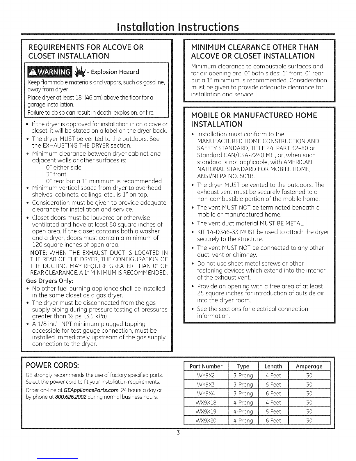
POWER CORDS:
GEstrongly recommends the useof factory specified parts.
Selectthe power cord to fit your installation requirements.
Order on-line at GEApplianceParts.com, 24 hours a day or
by phone at 800.626.2002during normal businesshours.
Part Number Type Length Amperage
WX9X2 ]5-Prong 4 Feet 30
WX9X3 3-Prong 5 Feet 30
WX9X4 3-Prong 6 Feet 30
WX9X!8 4-Prong 4 Feet 30
WX9X!9 4-Prong 5 Feet 30
WX9X20 4-Prong 6 Feet 30