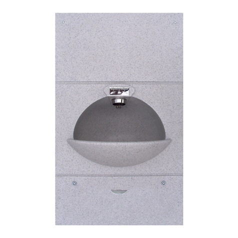
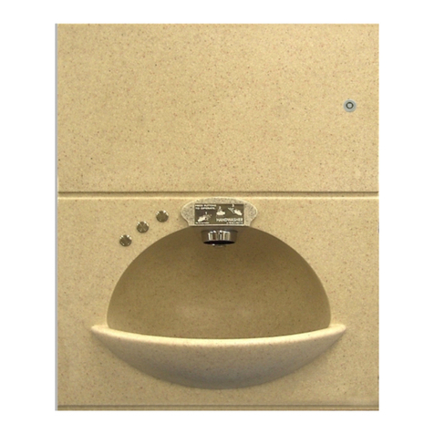
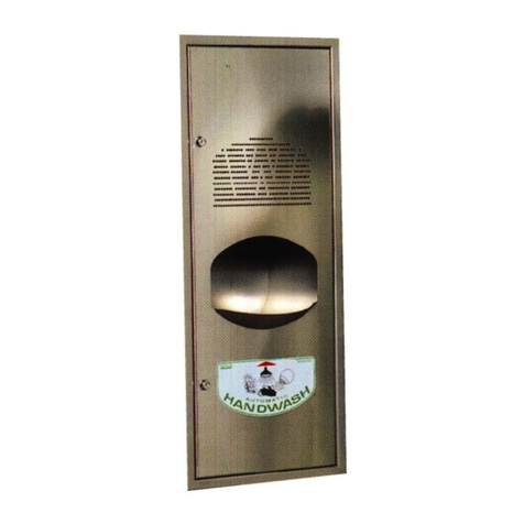
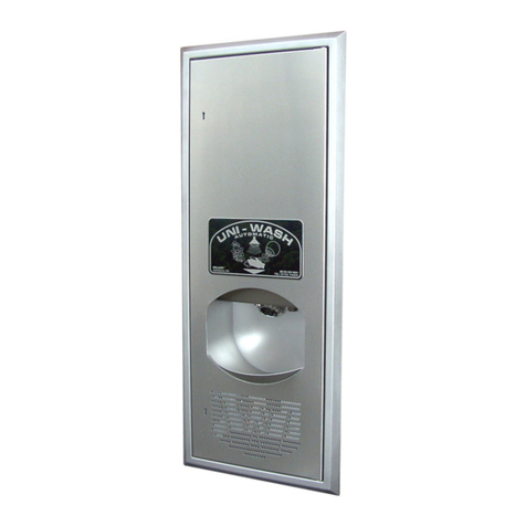
Wallgate PSH-20 Series User manual

Product Manual
Model PSH-20 series
Hand Wash Dryer

Revision 7
2
Product Manual PSH-23

Revision 7
3
Table of Contents
1. Disclaimer ..........................................................................................................................4
2. Conventions .......................................................................................................................4
3. Warning..............................................................................................................................4
4. Note ...................................................................................................................................4
5. Numbered procedures........................................................................................................4
6. Bullet lists...........................................................................................................................4
7. Menu items.........................................................................................................................5
8. Glossary.............................................................................................................................5
9. Overview............................................................................................................................6
10. Installation and Commissioning........................................................................................7
10.1 Package Contents..........................................................................................................7
10.2 Site Preparation .............................................................................................................7
10.3 Mounting the control unit and basin................................................................................8
10.4 Cabinet Preparation and Fitting......................................................................................9
10.5 Water Supply Connection.............................................................................................10
10.6 Electrical supply connection.........................................................................................11
10.7 Soap Liquid Fitting........................................................................................................12
10.8 Commissioning for Use (PSH Control Cabinets) ..........................................................12
10.9 Commissioning for use (WDC100/200 Control Units)......Error! Bookmark not defined.
10.10 Technical Specifications.............................................................................................13
11. User and Maintenance Instructions ................................................................................20
11.1 Introduction ..................................................................................................................20
11.2 Operation.....................................................................................................................20
11.3 Replenishing the Soap.................................................................................................21
11.4 Adjusting the Water Temperature.................................................................................22
11.5 Maintenance.................................................................................................................22
11.6 Warranty ......................................................................................................................23

Revision 7
4
1. Disclaimer
The specifications of Wallgate products can change without notice because of
developments in design and manufacturing.
2. Conventions
Certain conventions are used in this manual to make it easier to read and
understand. They are given in the sections below.
3. Warning
A warning with white text on a red background is used to give information about
hazards that can cause injury or death. Read and understand these warnings before
you install and commission the CWC water closet. Failure to heed these warnings can
have serious consequences.
WARNING! This is a warning!
4. Note
A note with black text on a yellow background is used to draw your attention to
important and useful information.
NOTE: This is a note.
5. Numbered procedures
Steps in procedures are numbered, starting from 1.
1. This is step 1.
2. This is step 2 etc.
6. Bullet lists
•A bullet list is used to give information that is not sequential.

Revision 7
5
7. Menu items
Menu items, submenu items and settings, where available, are given in bold.
8. Glossary
The glossary lists all words, abbreviations and technical terminology used in this
manual, along with a short description of these terms.
Term
Description
Anti-Ligature
Recently we have become aware that there is some
inconsistency in the market as to the exact meaning of "anti-
ligature". Where we use this phrase in connection with our
products it means that we have designed and tested the
product in order to reduce any risk of that product being used
as a ligature attachment point.
Piezo electric Push button
A piezoelectric pushbutton converts the force applied to the
face of the pushbutton into an electrical signal. Piezoelectric
pushbuttons are used in the ALS_180 to operate the hot and
cold water taps.
IR Sensor
The infrared (IR) sensor detects infrared radiation from your
hand, this creates an electrical signal. IR sensors are used in
the ALS_180_IR to operate the hot and cold water taps.
Operate the sensor switch by holding your hand within 50mm
of the sensor.
BSP
The British Standard Pipe (BSP) thread is a family of standard
screw thread types that has been adopted internationally for
interconnecting and sealing pipe ends by mating an external
(male) with an internal (female) thread.1
Push fit
Push fit type fittings are a plumbing pipe connector that
pushes onto the copper tube and has an integral rubber seal
to ensure a water tight connection. The basin utilizes
individual push fit components and fittings cast into the solid
surface material.
Pneumatic Operation
The water operation is controlled by a pneumatic water valve
that is operated when the user presses a stainless steel push
button that then drives a diaphragm air pump which is
connected by a flex air hose to the pneumatic water valve.
The pneumatic water valve automatically closes after a preset
time duration which is adjustable.
1
Description sourced from Wikipedia at http://en.wikipedia.org/wiki/British_standard_pipe_thread
1
ed from Wikipedia at http://en.wikipedia.org/wiki/British_standard_pipe_thread

Revision 7
6
9. Overview
The PSH is an extremely safe in-cell hand wash solution. It includes integral soap
dispenser, instantaneous warm water heater, an optional cold water outlet, and warm
air hand dryer, all managed integrally.
An optional plug-in module for WC flush is available.

Revision 7
7
10. Installation and Commissioning
10.1 Package Contents
Before you begin the installation, make sure that you have the following items:
✓PSH-20: 1 x PSH basin fascia with mounting brackets, M10 studs & fixings, 1 x PSH
control cabinet, 1 x metal air duct, 1 x flexible water hose, 2 x button blanks with fixing
tube & nut, 1 x bottle of soap.
✓PSH-20R: 1 x PSH basin fascia with mounting brackets, M10 studs & fixings, 1 x
PSH control cabinet, 1 x flexible air duct, 2 x hose clips,1 x flexible water hose, 2 x
button blanks with fixing tube, 1 x bottle of soap.
✓PSHD20: 1 x PSH basin fascia with mounting brackets M10 studs & fixings,1 x PSH
control cabinet, 1 x metal air duct, 2 x flexible water hoses, 1 x bottle of soap.
✓PSHD20R: 1 x PSH basin fascia with mounting brackets M10 studs & fixings, 1 x
PSH control cabinet, 1 x flexible air duct, 2 x hose clips, 2 x flexible water hoses, 1 x
bottle of soap.
✓PSH-25-PNEU: 1 x PSH basin fascia with mounting brackets M10 studs & fixings, 1 x
PSH control cabinet, 1 x flexible water hose, 1 x Stainless steel push button with air
pump, air hose and pneumatic water valve.
NOTE: The PSH-23 model series that use a WDC electronic control unit sold
separately as an option are detailed in the PSH-23 product manual.
10.2 Site Preparation
•Prepare an opening in the wall surface, accurate to the dimensions shown on
the installation drawing provided with the product. It is important that the
aperture is square and within tolerance to the stated dimensions.
•An electrical supply (230v 50Hz) should be provided with a switched fused
spur-13Amp, double pole connection point that is local (within 0.7 metre) of
the Control cabinet (the contact separation of the fused switch spur should be
at least 3mm). The PSH unit comes with a 1 metre mains cable flex attached.
•A mains cold water supply with a static pressure of 2-3bar should be provided
to the rear of the wall below the cabinet mounting position and terminated with
a suitable isolating tap for final connection to the unit inlet connections. If the
unit is to be connected to a gravity (tank) fed supply, further advice should be
requested from Wallgate as the minimum required water pressure as stated
above is important to the performance of the unit water dispensing system.
•The basin includes a waste outlet pipe tail 1 ½” (40mm) connection. It should

Revision 7
8
be terminated to a suitable deep seal waste trap (not supplied) located 200mm
(Min) below the centreline of the basin waste pipe tail.
Warning! THIS APPLIANCE MUST BE EARTHED
10.3 Mounting the control unit and basin
•Remove the basin fascia, with attached waste pipe, M10 studs, installation
brackets (and air ducting if relevant to the variant being installed) from the
packaging.
•To fit the four threaded studs into the mounting points on the rear side of the
hand basin, apply ‘Loctite 270’ onto the first 15mm of thread on each stud end
to fit into the sink corner fixing points. Screw each one in by hand until it stops
& then un-screw the stud by two full turns,
NOTE: It is very important to install the studs correctly to prevent the stud
damaging the fascia.
•Note the recommended cure time of 6 hours at room temp. of 22°C or up to 24
hours at room temp. of 5°C for the Loctite to set.
•Models without cold water outlet. At the front top LH basin fascia position is
fitted 1 stainless steel operating button and bezel, marked ‘HANDWASH’ or
‘HANDWASH & DRIER’, (depending on model) at front RH position a blank
bezel plate to be fitted with either a plain plate or a plate with legend ‘NOT
DRINKING WATER’. For reference the bezels and operating button can be
removed by undoing the large flanged securing nuts from the back of the
fascia. When refitting the retaining nuts tighten to a torque of 13 Nm.
•Cold water outlet models. At the front top LH basin fascia position is fitted 2
stainless steel operating buttons and bezels, front LH marked ‘HANDWASH’
or ‘HANDWASH & DRIER’, (depending on model) front RH with a plain bezel.
For reference the bezels and operating buttons can be removed by undoing
the large flanged securing nuts from the back of the fascia. When refitting the
retaining nuts tighten to a torque of 13 Nm.
•Fit the solid surface basin fascia, with studs in place, fully into the aperture,
the flat underside of basin area sitting on bottom of aperture. Secure the unit
to the wall by placing the vertical retaining brackets onto the studs & fit M10
fixings as shown on the drawing on page 7 of this document.
NOTE: It is important to tighten the fixings adequately but avoid distorting the
metal brackets through excessive tightening. Tighten the M10 nuts to a torque
of 17Nm in a circular sequence. Do not overtighten as this may cause damage
to the fascia & retaining brackets.

Revision 7
9
•The front of the basin must be sealed to the wall face with hard set no pick
mastic such as Arbokol 1025 or Sikadur 33. The fascia has a 6mm chamfer
running around the rear mounting face for mastic sealing to the wall.
•The chamfer should be fully filled and shaped to give a anti ligature resistant
profile. Compliance with these requirements will ensure the maximum possible
security and ligature resistance of the product is maintained.
10.4 Cabinet Preparation and Fitting
•‘Local’, cabinet mounting. The Local installation position is detailed on the
drawings on pages 14 & 15 of this document.
•Fitting the air duct. With the basin fascia securely in place on the wall
correctly orientate & bolt the horizontal wall bracket onto the basin vertical
retaining brackets. The vertical and horizontal bracket/plate assembly will now
be correctly positioned for fitting the cabinet. The metal air duct should be
pushed through the rectangular aperture in the horizontal wall plate & engage
onto the metal air spigot on the top of the basin. This can be seen on the
drawings on pages 15 & 16 of this document. With the duct fully inserted onto
basin spigot the flange around the top of duct must fully engage onto face of
horizontal plate as shown. Depending on the wall thickness & the importance
of the metal air duct fitting correctly, the duct may require cutting to the correct
length. A template with cutting instructions is supplied with the product.
(Drawing number ‘INS_PSH_20 DUCT TEMPLATE’).
•Installation into walls less than 128mm thick. Mount the basin/fascia to the
wall using vertical mounting brackets as described at para. 3.5. If the unit is to
be mounted into a wall with a total thickness of less than 128mm then the
spacer mounting brackets supplied must be used to move the horizontal plate
forward. The spacer mounting brackets bolt onto the basin vertical retaining
brackets holding the fascia into the wall. The cabinet horizontal fixing plate
then bolts to the spacers. A drawing of this arrangement can be seen on page
10 of this document.
•Fitting cabinet to basin assy. The cabinet should be carefully lowered onto
the horizontal fixing plate. The fixing plate has two lugs protruding at an angle
which locate into cut outs on the back of the cabinet. When fully home the
cabinet should locate onto protruding lugs & rest on the bottom flange of the
horizontal plate. Check that the rear fan outlet aligns with the air duct. The
cabinet cut outs allow slight side to side movement to achieve a good aperture

Revision 7
10
alignment. Once in place insert the two M5 bolts supplied, through the bottom
flange of the horizontal fixing plate into the threaded holes in bottom of
cabinet. Fitting & aligning the cabinet onto its brackets can be seen on the
drawing on page 15 of this document.
•‘Remote’ cabinet mounting. The ‘Remote’ installation position is detailed on
the drawing on page 17 of this document.
•Fitting the cabinet. The fan outlet will be through the bottom of the cabinet.
•When fitting the basin fascia to the wall use only the vertical mounting
brackets. The horizontal mounting plate can then be fixed to the wall (using
the four, 9mm dia. fixing holes) in a position to suit the requirements on site.
NOTE: the remotely fitted horizontal mounting plate must be installed with
suitable fixings capable of supporting the control unit (& soap bottle if
relevant) a combined weight of 17kgs.
•Fitting the air duct. When installing the cabinet in a ‘Remote’position the air
flow from the cabinet will be via a ‘concertina’ type flexible duct to the round air
grille spigot on the top of the basin. Consideration should be given to making
this as short a distance as possible (it is recommended not to exceed a 1
metre path length of flexible duct), when installing flexible duct avoid the
following: the flexible air duct should be curved as gently as possible and
sharp 90° turns should be avoided. Extending the flexible air duct to any
longer than 1 metre with tight bends will result in a reduction of airflow to the
wash basin. (If the concertina flexible duct requires shortening so as to avoid
unnecessary loops etc, ensure duct end is cut squarely). Fully attach duct
ends onto protruding round spigots on underside of cabinet and top of basin,
secure with worm drive hose clips (supplied).
10.5 Water Supply Connection
NOTE: For installations, liable to freezing conditions, frost protection & pipe
insulation must be fitted.
WARNING! IF THE PSH UNIT INCLUDES THE OPTIONAL COLD WATER
OUTLET & THE WATER IS INTENDED FOR DRINKING, THEN IT IS THE
RESPONSIBILITY OF THE END CLIENT TO ENSURE THAT THE WATER
SUPPLY IS OF A SUITABLE QUALITY FOR DRINKING PURPOSES, THE
INSTALLER SHOULD CONSULT WITH OTHERS IF IN DOUBT WHEN
INSTALLING THE PRODUCT.
•Prior to final connection of the water supply to the PSH unit, the water supply

Revision 7
11
pipes must be flushed through so as to remove any debris & air locks.
WARNING! FAILURE TO CARRY THIS OUT MAY RESULT IN DAMAGE AND
FAILURE OF THE UNIT.
•Make the water supply connection to the 15mm connection on the unit water
inlet stop tap on the PSH.
NOTE: If a sealing compound has been used on the supply feeds, ensure that it
is not overly applied as dislodged particles will cause a blockage that may
result in possible damage to the PSH water system.
•For non-cold water outlet models. Attach the flexible water hose (supplied)
to the ½” BSP basin water nozzle on the top of the basin, connect the other
end of flexible hose into the hand wash water outlet.
•For models with the cold water outlet option. The basin requires a potable
(drinking) cold water supply suitable for human consumption. It is the
responsibility of the installation contractor and end client to ensure the cold
water supply is suitable in all respects for human consumption. Attach the
flexible water hoses (supplied) into the water nozzle elbow push-fits on the top
of the basin. Connect other end of hoses as follows, viewed from the rear of
the basin: the LH basin nozzle hose to loop round & connect to the RH cabinet
push-fit elbow, the RH basin nozzle hose loops round & connects to the LH
cabinet push-fit elbow.
•Waste connection. The basin includes a waste outlet pipe tail connection of 1
½” (40mm) size. It should be terminated to a suitable deep seal waste trap
(not supplied) located 200mm (Min) below the centreline of the basin waste
pipe tail.
10.6 Electrical supply connection
NOTE! The electrical connections must be carried out by a qualified electrical
engineer in accordance with nationally approved IEE Regulations.
•The unit will be supplied with a 1-metre flying lead for connection to the mains
‘switched fused spur’ supply.
•Earth bonding should be carried out to comply with the Nationally Approved
Regulations. An earth lead is attached to a common earth plate on the basin
fascia, connecting relevant Water and Soap nozzles and Air grille, the free end
of the earth lead must be securely connected to the M6 equi-potential earth
connection point protruding from the bottom of the PSH control cabinet.
•Control lead connection. With the PSH Control cabinet there are 2 possible

Revision 7
12
connector positions in a row along the LH underside. The connector position
nearest to mounting wall is position ‘1’ and furthest away is position ‘2’. Attach
appropriate button operating flying leads into the relevant mating connectors
on the underside of cabinet as follows:
oPosition ‘1’: Hand Wash piezo button.
oPosition ‘2’: Cold Water piezo button. (Only if cold water option
included).
10.7 Soap Liquid Fitting
•Soap container bracket mounting: The soap container should be hung by
the small bracket & cabinet fixings supplied (see drawing on page 6) and can
be placed in different positions to suit requirements on site. There are fixing
positions on each side & front of the cabinet. Alternatively, the bracket can be
mounted on a wall close by.
•Soap pipe connection. Push the small dia. clear plastic hose which is trailing
from under the cabinet onto the inline connector on the length of soap tube
fitted to the soap nozzle on the basin fascia. Secure with the cable tie
provided.
•Hang a full soap container 2.5 or 5ltr onto the soap bracket. Place the tube
(with bung attached) into the bottle, push fit the plastic bung into the bottle
neck.
10.8 Commissioning for Use (PSH Control Cabinets)
•With the cabinet cover removed, fully open the water inlet taps on the unit
located under the cabinet. Check all plumbing connections to the unit for any
leaks & then refit the cover. If relevant to the model being commissioned,
check that the soap tube has been fitted to the soap nozzle on the top of
basin. For adjusting water flow from the basin water nozzle(s) refer to ‘User
operating & maintenance instruction for model PSH’ section 11.4.
•Switch ‘ON’ the electrical supply at the fused spur isolator connection point &
then on the unit at the cabinet switch (Positioned on the left-hand side of the
cover). The cabinet switch should illuminate red.
•Prime the soap system (if fitted) by pressing the priming switch located on the
rear cover next to the mains on/off switch, until the soap is dispensed from the
nozzle, (as detailed in ‘User operating & maintenance instruction for model
PSH’ section 11.3).
•On completion of the above, this document should be passed to the customer.

Revision 7
13
10.9 Technical Specifications models PSH**-20 series
Table 1. Technical specifications
Models with built in water heater
Thermal Cut Out
46°C (+/- 3°C)
Temp of water with
flow rate 1.8 ltr/min
Raises the ambient by 15°C ±2°
Water Supply
Minimum pressure 2 Bar (Static)
Maximum pressure 3 Bar (Static)
Supply pipe size 15mm copper
Waste connection
1 ½” (40mm) pipe, for connection to 1 ½" trap. (Trap
not supplied)
Power supply
230V AC 50/60Hz 13 Amp single phase
Power rating
Maximum power rating 3000 W
Weight
36kg
Dimensions
200mm (W) x 150mm (H) x 80mm (D)
Enclosure IP Rating
IP20
Regulatory
compliance
Complies with RoHS, LVD 2006/95/EC and EMC
2004/108/EC directives.

Revision 7
14

Revision 7
15

Revision 7
16

Revision 7
17

Revision 7
18

Revision 7
19

Revision 7
20
11. User and Maintenance Instructions
11.1 Introduction
•Welcome to the PSH hand wash unit. The unit has been designed and
manufactured to a high standard from quality materials. If these user
instructions are followed, the unit will give reliable efficient service. If you need
any further information or help, please contact Wallgate Ltd.
•Activating the Hand Wash button, the unit dispenses (depending on the
relevant model) liquid soap, warm water & heated air drying into the basin
area, combined in a pre-set cycle designed to be highly effective in hand
washing at low cost. (excessive use within a pre-set time period will engage a
pre-set timed lockout).
•Activating the Cold-Water Outlet button, (if fitted) a pre-set amount of water is
dispensed from the drinking water nozzle. (excessive use within a pre-set time
period will engage a pre-set timed lockout).
•Activating the WC Flush button (Option), will operate the WC cistern flush
valve followed by a timed cistern fill.
•Your installer will have passed to you this product manual which includes the
installation & commissioning instructions.
•The unit basin fascia is manufactured in a tough polyester solid surface
material in white & granite effect colours. Small variations in colour may occur
from one unit to the next.
11.2 Operation
•The electrical supply to the unit is turned “ON” or “OFF” by the isolation switch
installed adjacent to the appliance by the installer. Should a fault develop on
the unit this switch must be turned OFF. The unit is also fitted with its own
internal isolating switch mounted at the rear cover. Access to this should be by
qualified or competent personnel only. Position “0” indicates OFF and position
“1” is ON.
WARNING: THIS UNIT MUST NOT BE OPERATED IF THE WATER SUPPLY IS
TURNED OFF.
•To use the Hand wash, activate the piezo touch button marked ‘HANDWASH
& DRIER’ on the basin front. There is a short delay to allow you to place your
hands centrally inside & towards the back of the bowl. The water nozzles &
This manual suits for next models
5
Table of contents
Other Wallgate Dryer manuals
Popular Dryer manuals by other brands

Barton
Barton 99816 Owner's manual and safety instructions

Beko
Beko BDP710MG user manual

Amana
Amana W10233410A Use and care guide

GE
GE DWSR473EVAA Dimensions and installation information

Bosch
Bosch WQG23108GR User manual and installation instructions

Siemens
Siemens WQ46B2C9GB User manual and installation instructions

Siemens
Siemens WT43H07CDN Installation and operating instructions

Samsung
Samsung DV52J8700E user manual

Maytag
Maytag Perfoma PYE4500 user guide

Hotpoint
Hotpoint TVEL 75 Experience Instruction booklet

Bosch
Bosch WTE863000US Operating instructions & installation instructions

GE
GE DDE7207R Use and care guide