GE JP380 Training manual

Use and Care & Installation Guide
Electric Grill
GE Appliances
Safety Instructions ................. 2–4
Operating Instructions, Tips
Controls ..................................................... 5
Features ..................................................... 4
Grill Modules......................................... 6–9
Grilling Guide............................................ 9
Ventilation System.................................. 10
Care and Cleaning................. 10–12
Control Knobs ......................................... 10
Grease Jar ............................................... 10
Grill Element ........................................... 11
Grill Grates .............................................. 12
Grill Rocks ............................................... 12
Porcelain Cooktop................................... 11
Ventilation System.................................. 11
Problem Solver .......................... 20
More questions ?…call
GE Answer Center® 800.626.2000
Installation
Instructions.............................. 13–19
Consumer Services................. 23
Appliance Registration ............................. 2
Important Phone Numbers .................... 23
Model and Serial Numbers...................... 2
Warranty .................................................. 24
8111P149-60
209622A
164D2966P183
49-8670-1
Model: JP380
03-04 JR

22
HELP US HELP YOU…
Before using your grill, read this guide
carefully.
It is intended to help you operate and maintain your
new grill properly.
Keep it handy for answers to your questions.
If you don’t understand something or need more help, call:
GE Answer Center®
800.626.2000
24 hours a day, 7 days a week
How to Remove Packaging Tape.
To assure no damage is done to the finish of the
product, the safest way to remove the adhesive left
from packaging tape on new appliances is an application
of a household liquid dishwashing detergent, mineral
oil or cooking oil. Apply with a soft cloth and allow
to soak. Wipe dry and then apply an appliance polish
to thoroughly clean and protect the surface.
Write down the model and serial
numbers.
You’ll find them on the right side of the vent
chamber. It is visible inside the cabinetry.
These numbers are also on the Consumer Product
Ownership Registration Card that came with your
grill. Before sending in this card, please write these
numbers here:
Model Number
Serial Number
Use these numbers in any correspondence or service
calls concerning your grill.
If you received a damaged grill…
Immediately contact the dealer (or builder) that sold
you the grill.
Save time and money.
Before you request service…
Check the Problem Solver in the back of this guide.
It lists causes of minor operating problems that you
can correct yourself.
IF YOU NEED SERVICE…
To obtain service, see the Consumer Services page
in the back of this guide.
We’re proud of our service and want you to be
pleased. If for some reason you are not happy with
the service you receive, here are 2 steps to follow
for further help.
FIRST, contact the people who serviced your
appliance. Explain why you are not pleased.
In most cases, this will solve the problem.
NEXT, if you are still not pleased, write all the
details—including your phone number—to:
Manager, Consumer Relations
GE Appliances
Appliance Park
Louisville, KY 40225

3
Important Safety Instructions
IMPORTANT SAFETY INSTRUCTIONS
Read all instructions before using this appliance.
When using electrical appliances, basic safety
precautions should be followed, including the
following:
• Use this grill only for its intended use
as described in this use and care guide.
• Be sure your appliance is properly installed
and grounded by a qualified technician in
accordance with the provided installation
instructions.
• Do not assume that you know how to operate
all parts of the grill. Some features may work
differently from those on your previous cooktop.
• Do not attempt to repair or replace any
part of your grill unless it is specifically
recommended in this guide. All other servicing
should be referred to a qualified technician.
• Have the installer show you the location
of the circuit breaker or fuse. Mark it for easy
reference.
• Before performing any service, disconnect
the grill power supply at the household
distribution panel by removing the fuse
or switching off the circuit breaker.
• Do not leave children alone or unattended
while the grill units are in operation.
They could be seriously burned.
• Do not allow anyone to climb, stand or hang
on the grill.
•
CAUTION: Items of interest to children should
not be stored in cabinets above the grill—children
climbing on the grill to reach them could be
seriously injured.
• Never wear loose-fitting or hanging garments
while using the grill.
Be careful when reaching for
items stored over the grill. Flammable material could
be ignited if brought in contact with hot surfaces and
may cause severe burns.
• Use only dry pot holders—moist or damp pot
holders on hot surfaces may result in burns from
steam. Do not let pot holders touch hot surface
units. Do not use a towel or other bulky cloths in
place of a pot holder.
• For your safety, never use your appliance for
warming or heating the room.
• Keep the vent grille, vent chamber and the
grease filters clean to maintain good venting
and to avoid grease fires.
• Do not let cooking grease or other flammable
materials accumulate on or near the grill.
• Do not store flammable materials near the
grill. Do not store or use combustible materials,
gasoline or other flammable vapors and liquids in
the vicinity of this or any other appliance.
• Do not heat unopened food containers.
Pressure could buildup and the container could
burst causing an injury.
• Do not touch the grill surfaces or areas near
the grilling surface. These surfaces may be hot
enough to burn even though they are dark in
color. During and after use, do not touch, or let
clothing or other flammable materials contact
grill surface or areas nearby grill surface; allow
sufficient time for cooling first.
Potentially hot surfaces include the grill and areas
facing the grill.
• When cooking pork, follow the directions
exactly and always cook the meat to an internal
temperature of at least 170°F. This assures that,
in the remote possibility that trichina may be
present in the meat, it will be killed and the meat
will be safe to eat.
• Do not use aluminum foil to line the grill basin
or grill. Misuse could result in a shock, fire
hazard or damage to the grill.
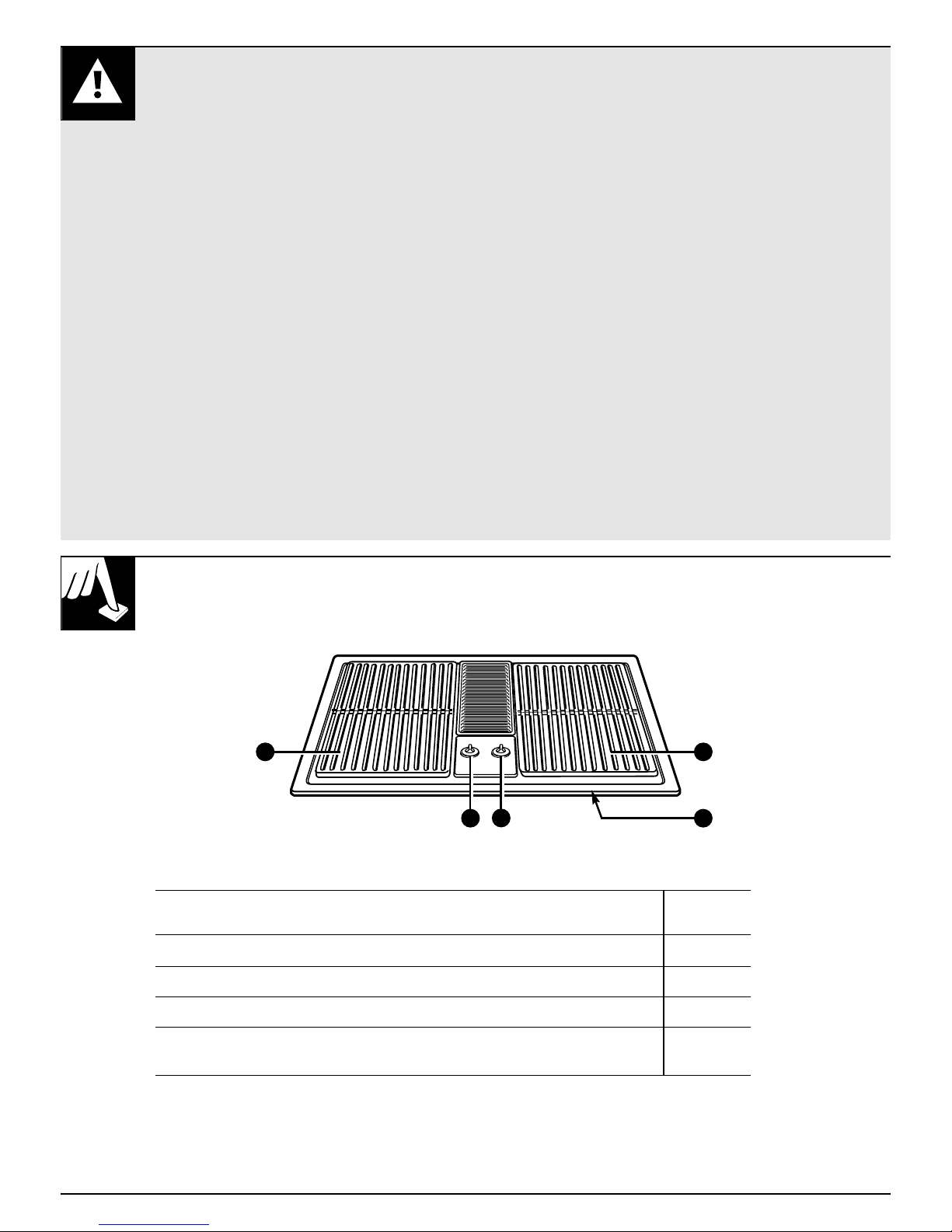
• Only the grill grate may be placed over the grill
heating element.
• Keep the grill basin, the grill-rocks, the grill
grate and the grease collector jar clean. Be
sure the drain hole in the grill basin is open. If
clogged, a fire can occur. Empty the grease jars
frequently.
•
Never clean the grill surface when it is hot. Some
cleaners produce noxious fumes and wet cloths
could cause steam burns if used on a hot surface.
• Do not use cookware on the grill section of
this cooktop.
(continued next page)

4
IMPORTANT SAFETY INSTRUCTIONS
(continued)
• To avoid the possibility of a burn or electric
shock, always be certain that the controls
are at the off position and all units are cool
before attempting to remove the grill grates
and grill-rocks.
• Never leave the area while using the grill.
• Do not replace the grease collector jar with
a mayonnaise jar which could break when hot
grease drips into it. Replace with any regular
canning jar.
• To control flame-ups,
turn down the heat setting
to FAN rather than off. This keeps the downdraft
vent blower on. Use a long-handled utensil to
carefully remove the food from the grill. These
steps should control the flame until it eventually
goes out. If it does not, cover the entire grill module
with a cookie sheet or the lid from a large roasting
pan. Use a pot holder to remove this later because it
will be hot.
• Never use water on a grease fire. Smother fire
or flame or use a multi-purpose dry chemical or
foam-type extinguisher.
• The use of any accessory not recommended by
GE may cause injuries.
• Fuel such as charcoal briquettes is not to be
used with this appliance.
• Do not operate with damaged cooking element
after any malfunction until proper repair has
been made.
• Keep all switches off when unit is not in use.
• This appliance is for household use only.
SAVE THESE
INSTRUCTIONS
Model: JP380
Explained
Feature Index on page
1 Grill Modules 6–9, 12
2 Control Knob for Left Grill Element 5, 10
3 Control Knob for Right Grill Element 5, 10
4 Model and Serial Numbers 2
(Located on the right side of the ventilation chamber.)
23
1
4
FEATURES OF YOUR GRILL
1

5
CONTROLS
The variable controls for the grill element provide flexibility in heat
setting selection.
Important Safety Instructions Features of Your Grill Controls
How to Set the Controls
1. Push the control knob down. 2. Turn the knob in either direction
to the desired heat setting.
The control must be pushed
down to set only from the OFF
position. When the control is in
any position other than OFF, it
may be rotated without pushing
it in.
Be sure you turn the control knob
to OFF when you finish cooking.
Cooking Guide for Using Heat Settings
The amount and type of food being cooked, weather
conditions and voltage will influence the setting
needed for best cooking results. The setting indicated
should serve as a guide while you become familiar
with your cooktop.
HI Preheat for all foods, cook steak and
hot dogs.
9–10 Cook pork chops, fish and chicken.
Fan Manual control of fan.

6
GRILL
The grill consists of two black grill grates, a grill element and
two grill-rocks.
To Install the Grill
1. Before installing grill components, be certain the
control knobs are in the OFF position.
2. Lift the grill element. Place the two grill-rocks into
an empty grill basin with their handles running
parallel to the front of the cooktop. These grill-rocks
must be used since they support the grill element.
3. Lower the grill element until it rests on the handles of
the grill-rocks.
4. Place the black grill grates on the top of the cooktop.
To Remove the Grill
1. Remove the grill components once they are cool.
Be sure the control knobs are in the OFF position.
2. Remove the grill grates.
3. Lift the grill element and remove the grill-rocks.
Automatic Ventilation
The vent fan comes on automatically when the grill is turned on and
turns off automatically when the grill is turned off.

GRILLING
Using the Grill
• Before using the grill for the first time, wash grill
grates in hot soapy water. Rinse and dry.
• Precondition new grates and grill-rocks by brushing
with vegetable oil or spraying with a non-stick coating
such as Pam®. Do this every time before you grill.
• For easier clean-up, spray grates and grill-rocks
with a non-stick coating.
• Preheat the grill on HI for 5 to 10 minutes.
Preheating improves the flavor and appearance
of meats and quickly sears the meat to help retain
the juices.
• Excessive amounts of fat should be trimmed
from meats. Some fat is necessary to produce the
smoke needed for that smoked “outdoor” flavor.
However, excessive fat can create cleaning and
flare-up problems.
• Never leave the grill unattended during
operation.
• Allowing excessive amounts of grease or drippings
to constantly flame voids the warranty on the grill
grates. Excessive flare-ups indicate that either the
grill interior needs to be cleaned, excessive amounts
of fat are in the meat or that the meat was not
properly trimmed.
• Grease drippings will occasionally ignite to produce
harmless puffs of flame for a second or two. This is
a normal part of the cooking process.
IMPORTANT:
• Do not use aluminum foil inside the grill area.
• Do not use charcoal or wood chips in the
grill area.
• Do not cover grates completely with meat.
Leave air space between each steak, etc. to
allow proper ventilation as well as to prevent
flare-ups.
• Do not allow the grill-rocks to become
overloaded with grease. Clean frequently.
What To Do If a Flare-Up Will Not Stop
1. Immediately turn the control switch to the fan position.
2. Remove the meat from the grill.
Grilling Tips
The following suggestions are good rules to follow
and will increase your enjoyment of the equipment.
Be sure to follow directions in this guide for using
the grill.
Suggested cooking times and control settings are
approximate due to variations in meats and electrical
voltage. Additionally, times will also vary depending
on the location of the grill (enclosed versus open
area; cross ventilation). Experience will quickly
indicate cooking times as well as which settings
work best.
For best results, buy top grade meat. Meat that is
at least 3/4 inch will grill better than thinner cuts.
For the attractive “branded” look on steaks, be sure
the grill is preheated. Allow one side of the meat to
cook to the desired doneness, or until the juices
appear on the top surface, before turning. Turn steaks
and hamburgers just once. Moving the food around
causes loss of juices.
To help retain meat juices, salt after turning meat or
after cooking is completed.
Should grilled foods be prepared and ready before
you’re ready to serve, turn controls to a low setting
and cover food with a single sheet of foil. Food will
continue to cook.
When basting meats or applying sauces to foods,
remember that excessive amounts wind up inside
your grill and do not improve the food flavor. Apply
sauces during the last 15 to 20 minutes of cooking
time unless the recipe specifies otherwise. Sugar-
based marinade (for example, barbecue sauce) will
caramelize on grill grates and grill-rocks and will
create a cleaning chore.
There are many meat marinades which will help tenderize
less expensive cuts of meat for cooking on the grill.
Certain foods, such as poultry and non-oily fish, may
need some extra fat. Brush with oil or melted butter
occasionally while grilling.
Use tongs with long handles or spatulas for turning
meats. Do not use forks as these pierce the meat,
allowing juices to be lost.
Score the fat on the edges of steaks but do not cut
into the meat to prevent curling while cooking.
7
Grill Grilling
(continued next page)

GRILLING
(continued)
Questions and Answers
Q. I followed the cooking times suggested in the
grilling guide but my foods were not done
properly. Is there something wrong with my
grill?
A. Probably not. Suggested cooking times should
be used only as a general guide. Variables in food
and location of the grill can change cooking times
required.
Q. How can I keep barbecued meats from
developing an unattractive burned look
and taste?
A. Sauces containing sugar will often burn if used
during the entire cooking time. If your favorite
sauce contains sugar, try adding it only during the
last 15 to 20 minutes of cooking time for best
results.
Q. When cooking many individual foods, what can
I do to insure that foods will cook evenly?
A. When cooking foods of various sizes and
thicknesses, start larger or thicker pieces first
and add quicker cooking, smaller pieces later.
Press the meat lightly to lie flat on the grill. Slash
the fat on the edges of steaks and chops to prevent
curling. Break the joints of split chickens so they
will lie flat.
Q. My grilled meats sometimes come out drier
than they should. What can I do to help
prevent this?
A. Season meats after cooking rather than before—
salt can draw out juices and dry out meat. Use
tongs to turn and rearrange meats on the grill;
forks will pierce the meat and release juices.
8

9
GRILLING GUIDE
Season grill grates. Preheat the grill on high for 5 to 10 minutes for best
flavor. The times given are based on grilling in an enclosed area. If the grill
is located in an area with cross ventilation, cooking times will need to be
increased (up to twice as long).
Type Control Setting Cooking Time Procedure
Meat
Steak (1/2 to 3/4″)
Rare HI 9 to 12 minutes Turn after 5 to 6 minutes.†
Medium HI 12 to 19 minutes Turn after 6 to 9 minutes.
Well HI 16 to 23 minutes Turn after 8 to 11 minutes.
Steak (1 to 11⁄2″)
Rare HI 10 to 17 minutes Turn after 5 to 8 minutes.†
Medium HI 19 to 26 minutes Turn after 9 to 12 minutes.
Well HI 24 to 32 minutes Turn after 12 to 16 minutes.
Hamburgers (1/2 to 5/8″) 10 15 to 25 minutes Turn after half the time.
Pork chops 10 30 to 40 minutes Turn occasionally.
Fully cooked smoked pork chops HI 10 to 15 minutes Turn once. Glaze if desired.
Ham slices 10 15 to 20 minutes Turn once.
Pork ribs 10 50 to 60 minutes Turn occasionally. Brush
with barbecue sauce during
the last 15 minutes.
Fully cooked sausages
Hot dogs, brats, polish HI 5 to 10 minutes Turn once.
Fresh sausages
Links 10 10 to 15 minutes Turn occasionally.
Patties (3″diameter) 9 20 to 25 minutes Turn after half the time.
Italian sausage 9 20 to 25 minutes Pierce casing with a fork.
Turn once.
Poultry
Chicken
Pieces: bone-in 10 45 to 60 minutes Turn occasionally.
Boneless breasts 10 25 to 35 minutes Start skin side down,
turn occasionally.
Wings 10 20 to 25 minutes Turn frequently. Brush with
marinade or glaze during
last 5 minutes.
Cornish hen (halved) 10 35 to 40 minutes Turn occasionally.
Fish
Small, whole (11⁄2″) 10 20 to 25 minutes Brush with butter. Turn after
half the time.
Steaks (1″) 10 25 to 30 minutes Brush with butter. Turn after
half the time.
Fillets—with skin on (1/2″) 10 10 to 15 minutes Start skin side down. Brush
with butter. Turn after half
the time.
Shrimp (skewered) 10 10 to 15 minutes Turn and brush with butter
or marinade frequently.
Bread
Garlic bread HI 2 to 3 minutes Turn after half the time.
Hot dog or hamburger buns HI 1 to 2 minutes
†The U. S. Department of Agriculture says
“Rare beef is popular, but you should know that cooking it to only 140°F. means some
food poisoning organisms may survive.” (Source: Safe Food Book. Your Kitchen Guide. USDA Rev. June 1985.)
Grilling Grilling Guide

10
VENTILATION SYSTEM
The built-in vent system helps remove cooking vapors, odors and
smoke from foods prepared on the grill.
The vent fan comes on automatically when either grill is turned on and
turns off automatically when both grills are turned off.
To operate the vent fan manually, turn the control knob to the FAN setting.
Control Knobs and Control Area
The knobs on the control panel can be removed
with the controls in the OFF position. Pull each knob
straight up. Wash the knobs in warm soapy water
or a dishwasher; do not use abrasive cleansers or
materials. To replace each knob, match the flat part
of the knob opening with the spring on the shaft,
returning to the OFF position.
To clean the area under the control knobs, use
mild cleansers, such as soapy water or mild liquid
sprays such as 409. Wipe with a sponge, damp cloth
or paper towel. Do not scrub with S.O.S. pads or
abrasive cleansers.
Grease Jar
A grease jar is located below each grill basin under
the countertop. Check periodically to prevent spillovers.
Unscrew and remove. If the jar is broken, replace
with any heat tempered jar, such as a canning jar,
which has a standard screw neck.
NOTE: Make sure the grease jar is in place
before grilling.
CARE AND CLEANING
Before cleaning any part of your grill, be sure all controls are off.
Do not operate the grill without all parts in place.

11
Porcelain Cooktop
This finish is acid-resistant. However, any acidic foods spilled (such as fruit
juices, tomato or vinegar) should be cleaned up right away. Acids will
damage the finish if left on the porcelain.
If acids spill on the grill while it is hot, use a dry paper towel to wipe it
up right away. When the surface has cooled, wash with soap and water.
Rinse well.
For other spills, such as fat spatterings, wash with soap and water after
the surface has cooled. Rinse well. Polish with a dry cloth.
Ventilation System Care and Cleaning
Grill Element
Do not clean the grill element. Most soil will burn off during use.
Ventilation System
Vent Grille: The vent
grille lifts off easily
Wipe clean or wash
in the sink with mild
household detergents.
Filter: Turn off the fan
before removing. Turn
the filter retainer clip to
remove the filter. The
filter is a permanent
type and should be
cleaned when soiled.
Clean in the sink with
warm water and liquid
dishwashing detergent.
IMPORTANT: Do not operate the fan without the
filter. The filter should always be placed at an angle.
As you face the front of the cooktop, the top of the
filter should rest against the left side of the vent
opening and the bottom of the filter should rest
against the right side of the ventilation chamber at
the bottom. If the filter is flat against the fan wall,
ventilation effectiveness is reduced.
Ventilation Chamber: This area, which houses the
filter, should be cleaned in the event of spills or
whenever it becomes coated with a film of grease.
The ventilation chamber may be cleaned with a paper
towel, damp cloth or sponge and a mild household
detergent or cleanser.
(continued next page)

12
CARE AND CLEANING
(continued)
Grill Grates
These are made from cast aluminum and have a non-
stick finish.
The grates should be cleaned after each use.
They can be cleaned with detergent and a plastic
scrubber, such as Tuffy, or washed in the dishwasher
if burned-on residue is first removed. For heavy soil,
grates can be soaked in hot, soapy water mixed with
household ammonia.
Do not use metal brushes or abrasive scouring
pads or other scrubbers intended to clean outdoor
grills. These will remove the finish as well as
scratch the grates. Do not clean in a self-cleaning
oven or use oven cleaners on the grates.
Porcelain Grill Basin
This area, located under the grill-rocks, should be
cleaned after each heavy use of the grill. The grill
element must be lifted during the cleaning process.
To remove light soil, clean with soapy water or with
a cleaner such as 409. For easier cleanup, soak paper
towels in a household cleanser, lay in the burner
basin and soak for at least a half-hour or longer.
To remove moderate soil, scrub with Comet, Bon
Ami, a soft scrub cleanser or plastic scrubber.
To remove stubborn soil, spray with an oven cleaner.
Let soak overnight. Wipe clean. Rinse and dry.
Grill-Rocks
These are made from cast-iron which have been
coated with porcelain enamel.
The grill-rocks should be cleaned frequently or after
any excessive build-up of grease.
To clean light soil, use detergent and a plastic
scrubber or wash in the dishwasher after burned-on
residue is first removed.
For heavy soil, soak in hot, soapy water to which a
cleanser, such as household ammonia, has been added.
Stubborn spots on grill-rocks, such as burned-on
residue from sauces, can be scrubbed with a stiff
brush.
An oven cleaner can be used for burned on soil.
Follow manufacturer’s directions; spray on cleaner
and let soak overnight.
Do not clean grill-rocks in a self-cleaning oven.

13
INSTALLATION INSTRUCTIONS
IMPORTANT INSTALLATION
INSTRUCTIONS
Grill is U.L. listed for outdoor installation only.
CAUTION: Warranty is void on GE equipment
installed other than as recommended by
manufacturer. Recommended wall caps and
transitions must be utilized for proper operation
and installation.
CAUTION: For personal safety, remove
house fuse or circuit breaker before
beginning installation.
This appliance must be supplied with the
proper voltage and frequency, and connected
to an individual, properly grounded branch
circuit, protected by a circuit breaker or time
delay fuse. Proper electrical ratings should be
verified with listing on product’s rating plate.
The rating plate is located on the right side
of the ventilation chamber.
Be sure your cooktop is installed properly
by a qualified installer or service technician.
BEFORE YOU BEGIN
Read these instructions completely and
carefully.
IMPORTANT–OBSERVE ALL GOVERNING
CODES AND ORDINANCES.
NOTE TO INSTALLER: Be sure to leave
these instructions with the consumer.
TOOLS AND PARTS NEEDED
• Large flat blade screwdriver
• Saw
• Carpenter’s square
• Measuring tape or scale
PARTS LIST
• Electric grill base unit
• Literature pack
• 4 Grill grates
• 4 Grill rocks
• 1 Vent filter
• 1 Vent grille
• 2 Grease jars
(continued next page)

14
INSTALLATION INSTRUCTIONS
(continued)
IMPORTANT
Dimension “A”—Provide 2″ min. (5.08 cm)
cabinet clearance to motor for cooling purposes.
NOTE: Where possible, 6″(15.24 cm) is
recommended for motor/blower service.
Side Clearance—Grills installed near a side
wall should allow a minimum clearance of
6″(15.24 cm) for best venting performance, but
may be safely installed as near as 1″(2.54 cm)
from a side wall if required by space limitations.
Electrical Hookup—The unit should be
properly circuit protected and wired according
to local electrical codes. See electrical wiring
information on back. Unit power requirements
are located on the data plate.
Ducting Requirements—Use of a wall cap
required. See Step 5 “Install the Ductwork.”
You must allow room enough to remove and
empty grease containers.
Grease
Container
14″
155⁄8″
Minimum
Clearance
3″ (7.62 cm)
39.69 cm
A35.56 cm
117⁄8″
30.16 cm
17⁄8″
4.76 cm
(Min.)
*Blower can be
swiveled 90°
Tie down bolt
on each end
(front and rear).
Grease
Container
Grease
Container
79⁄16″
19.21 cm
287⁄8″1⁄16″
73.34 .16cm
2015⁄16″1⁄16″
53.18 cm
.16 cm
(Min.)
93⁄8″
23.81 cm
PREPARING FOR INSTALLATION
For ducting through the floor.
*The blower may be rotated for horizontal or vertical direction
by loosening nuts around the blower inlet, accessible inside the
ventilation chamber.
PREPARING FOR INSTALLATION
For ducting through the back wall.
*The blower may be rotated for horizontal or vertical direction
by loosening nuts around the blower inlet, accessible inside the
ventilation chamber.
93⁄8″
23.81 cm
13″
33.02 cm

15
EXCEPTION: Installation of a listed microwave
oven or cooking appliance over the cooktop shall
conform to the installation instructions packed
with that appliance.
Working areas adjacent to the cooktop should
have an 18″(45.7 cm) minimum clearance
between the countertop and the bottom of the
cabinet. If the clearance is less than 18″
(45.7 cm), the adjacent cabinets should be at
least 2″(5.08 cm) from the side of the cooktop.
Proper Electrical Supply
You must provide an adequate electrical supply
system as required for your cooktop. All wire
connections must be in accordance with local
codes and properly insulated. Check with local
utility for governing electrical codes and
ordinances. In the absence of local electrical
codes, the National Electrical Code, NFPA No.
70, must be followed. A copy of the National
Electrical Code, NFPA No. 70, can be obtained
by writing to:
National Fire Protection Assn.
Batterymarch Park
Quincy, Massachusetts 02269
A three-wire, single phase, A.C. 120/240 volt or
120/208 volt, 60 cycle electrical system
(properly circuit protected to meet local codes
or NFPA No. 70) must be provided. Unit must
be properly grounded in accordance with local
wiring code. The following chart recommends
the minimum circuit protection and wire size if
the appliance is the only unit on the circuit. If
smaller sizes of wire are used, the unit efficiency
will be reduced and a fire hazard may be
created. It is advisable that the electrical wiring
and hookup be accomplished by a competent
electrician.
STEP 1
INSTALLING CABINETS OVER YOUR
COOKTOP
Avoid placing cabinets above the cooktop unit,
if possible, in order to reduce the hazards
caused by reaching over heated surface units.
• Make sure the wall coverings around the
cooktop can withstand heat generated by the
cooktop up to 200°F. (93°C.).
• If cabinets are placed above the cooktop,
allow a minimum clearance of 30″(76.2 cm)
between the cooking surface and the bottom of
unprotected cabinets unless the underside of the
cabinets above the cooktop is protected with not
less than 1/4″(.63 cm) insulating flame-retardant
millboard covered with sheet metal not less than
0.0122″(0.031 cm) thick.
• Clearance between the cooking surface and
protected cabinets MUST NEVER BE LESS
THAN 24 INCHES. The vertical distance from
the plane of the cooking surface to the bottom of
adjacent overhead cabinets extending closer
than 1″(2.54 cm) to the plane of the cooktop
sides must not be less than 18″ (45.7 cm).
25″
(63.5 cm)
30″
(76.2 cm) min
30″
(76.2 cm)
13″
(33.02 cm)
18″
(45.7 cm)
1″(2.54 cm) min to wall
We recommend at least 6″(15.24 cm)
for best venting performance.
36″
(91.4 cm)
(continued next page)

16
INSTALLATION INSTRUCTIONS
(continued)
Supply Connection
All electrical connections are to be protected from the
elements and be in accordance with local codes for
outdoor wiring. This appliance is to be permanently
wired.
Bring supply leads into bottom opening of the internal
wiring box. Make ALL wire connections inside this box.
Install the wiring box cover supplied with this unit and
insure that the cover gasket is in place.
Recommended Minimum
K.W. Rating Circuit Wire Size
on Serial Protection AWG
Plate in Amperes
0–4.1 20 12
4.2–6.9 30 10
STEP 2
PREPARING THE COUNTERTOP
Cut out the opening as shown in the diagram.
Measure carefully when cutting the countertop,
making sure the sides of the opening are parallel
and the front and rear cuts are exactly
perpendicular to the sides.
The front of the opening must clear the front
support rail on the cabinet and the rear of the
opening must clear the rear support of the cabinet.
Chamfer all exposed edges of decorative laminate
to prevent damage from chipping.
Radius corners of cutout and file to insure
smooth edges and prevent corner cracking.
Rough edges, inside corners which have not been
rounded and forced fit can contribute to cracking of
the countertop laminate.
Countertop must be supported within 3″(7.6 cm) of
cutout.
Not less than 17⁄8
″
4.8 cm
Not less than 11⁄4″ 3.2 cm
63⁄8″ min. cut-out to
wall (16.2 cm)
63⁄8″ min. cut-out to
wall (16.2 cm)
Countertop cut-out dimensions Back of Counter
Front of Counter
2015⁄16 1⁄16
″
53.2 .16 cm
287⁄81⁄16″ (JP380)
73.3 cm .16 cm
STEP 3
PREPARE FOR DUCTWORK
NOTE: Ductwork MUST be vented outside.
DO NOT vent into a wall, ceiling, crawlspace,
attic or any concealed space.
Determine the best route for ductwork; it can be
routed in a variety of ways depending on the type
of installation.
Typical duct arrangements.
Optional duct arrangement under concrete slab.
Inside wall
cabinet
Up inside wall to roof or
overhang.
Directly to outside.
Between floor joists. Thru cabinet toe space.
Peninsula or island
Peninsula
Outside wall
cabinet
31⁄4″X10″
(8.2 cm X 25.4 cm)
Transition elbow
Transition
elbow
31⁄4
″X10″
(8.2 cm X 25.4 cm)
NOTE: PVC sewer pipe type PSM 12454-B
Schedule 40 ASTM D1785.
Wall cap
6″(15 cm)
dia. 90°
metal elbow
6″(15 cm) dia.
metal duct
16″
(40.6 cm)
max.
Concrete
slab
6″(15 cm)
dia. PVC
sewer pipe
12″
(30 cm)
min.
6″
(15 cm)
dia. PVC
coupling
6″
(15 cm)
dia.
PVC
coupling
6″(15 cm)
dia. metal
duct
5″to 6″
(12.7 cm to 15 cm)
metal transition
6″(15 cm)
dia. PVC
sewer pipe
6″(15 cm) dia.
PVC sewer pipe
elbow
6″(15 cm) dia.
PVC sewer pipe
elbow
Pack tightly with gravel
or sand completely
around pipe.
30′ (9.1 m)-0″max

17
3. Use quality metal duct of at least 26 gauge
galvanized or 24 gauge aluminum. Inferior
quality pipe and fittings can cause up to twice
the restriction shown and is a poor value. See
the Prepare for Duct Work section of this guide
for optional under-slab ducting. Local codes may
require a heavier gauge material or restrict PVC.
4. Distance between adjacent fittings (elbows,
transitions, etc.) should be at least 18″. The
further the better. Closer distance promotes
turbulence which reduces airflow.
5. Handmade crimps are likely to cause restrictions.
6. If an alternate wall or roof cap is used, be
certain duct size is not reduced, and that there
is a backdraft damper. It is best to use listed
caps to be certain of proper performance.
7. Thermal breaks: In areas of extreme cold
weather, it may be necessary to provide a short
length of nonmetallic duct as close to the wall as
possible, to prevent conduction along the metal
duct.
8. High altitude installations: It is advisable to
reduce allowable duct run by 20%.
9. Follow the duct calculation in this guide
carefully for best performance and satisfaction.
STEP 4
PLAN THE DUCT RUN
1. Make a sketch of the total system.
Identify the type of each fitting and the length of
straight pipe.
2. Enter your run into the Duct Length Chart in
this guide. Elbows, wall caps and other fittings
are shown in the chart with their equivalent
straight duct length. Each fitting value must be
added to the amount of straight duct length used
to determine the overall straight duct equivalent
length. Use the following examples as a guide.
3. Using good quality ducting material, install
per these instructions. A few minutes and
pennies spent now will pay long term dividends
for the life of the cooktop.
STEP 5
INSTALL THE DUCTWORK
• Ducting must conform to local code materials
and “make-up” requirements—300 CFM
minimum.
• IMPORTANT: Save for local electrical
inspector’s use.
• Ducting a cooktop is easy but critical for
proper performance.
• After reading these instructions, plan the
duct run.
• Use the “Duct Length Chart” to find the
equivalent length of the run.
• Shift the blower to “high range” if indicated
(done by snapping the “restricter ring” out of
the blower inlet). Be sure blower is not running.
• Install the duct hardware.
GENERAL CONSIDERATIONS:
1. Use 6″diameter round or 31⁄4″x10″rectangular only.
2. Use a 5″to 6″transition (or a 5″round to
31⁄4″x10″rectangular transition) at the blower outlet.
The number of additional elbows or transitions in
the system should be limited to three.
IMPORTANT
Total allowance duct system is:
90′with 6″round wall cap
80′with 31⁄4″x10″wall cap
Low range is up to 60′
High range is 61 to 90′
STEP 6
SHIFTING THE BLOWER FROM “LOW
RANGE” TO “HIGH RANGE”
This cooktop is equipped with a dual range
blower. It is shipped from the factory in low
range for most installations. If the Equivalent
Duct Length exceeds 60 feet it must be shifted
to high range. Do not shift to high range for
shorter lengths. This will cause excessive noise
and loss of conditioned air.
To shift to high range
be sure the blower is
stopped. Remove the vent
grill. Remove the filter and
intake guard. Pop the
spring loaded “restricter
ring” out of the blower
inlet. Replace the intake
guard, grill and filter.
(continued next page)

18
INSTALLATION INSTRUCTIONS
(continued)
Example 2
Duct Fitting Number Total
Equivalent of Fittings Equivalent
Length Length of
Fittings
5″to 6″
Transition 1 1 1
6″Straight 1 2+4+6+4=16 16
6″Elbow 5 3 15
6″to
31⁄4″x10″
Transition 1 1 1
31⁄4″x10″
Straight 1 10 10
31⁄4″x10″
Wall Cap 20 1 20
Total 63
Example 1
Duct Fitting Number Total
Equivalent of Fittings Equivalent
Length Length of
Fittings
5″to 6″
Transition 1 1 1
6″Straight 1 2+4+6=12 12
6″Elbow 5 2 10
6″Wall Cap 28 1 28
Total 51
5″to 6″Transition
5″to 6″Transition
10′of 31⁄4″x10″Straight
6″to 31⁄4″x10″Transition
2′of 6″Round
2′of 6″Round
6″Elbow
6″Elbow
6″Elbow
6″Elbow
6″Elbow
4′of 6″Round
4′of 6″Round
4′of 6″Round
31⁄4
″x10″Wall Cap
6′of 6″Round
6′of 6″Round
6″Wall Cap

19
DUCT LENGTH CHART
Duct Fitting Number Total Equivalent
Duct Fitting Equivalent Length of Fittings Length–Fitting
8″Diameter 90° Elbow 5′
(1.52 m)
6″Diameter 45° Elbow 2.5′
(.76 m)
5″to 6″ Transition 1.0′
(12.7 cm to 15.24 cm) (.30 m)
6″to 31⁄4″x10″ 90° Elbow 5′
(15.24 cm to 8.26 cm x 25.4 cm) (1.52 m)
31⁄4″x10″ to 6″90° Elbow 9′
(8.26 cm x 25.4 cm to 15.24 cm) (2.75 m)
6″to 31⁄4″x10″ 90° Elbow 1′
(15.24 cm to 8.26 cm x 25.4 cm) (.30 m)
31⁄4″x10″ to 6″Transition 4.5′
(8.26 cm x 25.4 cm to 15.24 cm) (1.37 m)
5″to 31⁄4
″x10″ 90° Elbow 6′
(12.7 cm to 8.26 cm x 25.4 cm) (1.83 m)
31⁄4
″x10″ 90° Elbow 5′
(8.26 cm x 25.4 cm) (1.52 m)
31⁄4
″x10″ Flat Elbow 12′
(8.26 cm x 25.4 cm) (3.66 m)
6″ Wall Cap 28′
(15.24 cm) (8.53 m)
31⁄4″x10″ Wall Cap 20′
(8.26 cm x 25.4 cm) (6.10 m)
10″x10″ Roof Jack 0′
(25.4 cm x 25.4 cm) (0 m)
Thermal Break 2′
(.61 m)
6″Diameter Straight Duct–Feet 1′
(For flex duct multiply by 2.) (.30 m)
31⁄4″x10″Straight Duct–Feet 1′
(.30 m)
System Total
Air Flow
Air Flow
Air Flow
Air Flow
Air Flow
Air Flow
Air Flow this direction not recommended.

20
QUESTIONS?
USE THIS PROBLEM SOLVER
PROBLEM POSSIBLE CAUSE
GRILL IS NOT • Difficulty may be in the main distribution panel of your house caused by a
FUNCTIONING PROPERLY blown circuit fuse, a tripped circuit breaker, the main fuse or the main circuit
breaker, depending on nature of the power supply. If a circuit breaker is
involved, reset it. If the control box uses fuses, the circuit fuse (a cartridge-
type) should be changed. BUT ONLY BY SOMEONE FAMILIAR WITH
ELECTRICAL CIRCUITS. If, after performing 1 of these procedures,
the fuse blows or circuit breaker trips again, call for service.
NOTE: Apartment tenants or condominium owners should request their
building management to perform this check before calling for service.
• Grill heating element controls are not properly set.
FOODS STICK • Heat setting is too high.
TO GRILL • Grates weren’t seasoned prior to grilling.
EXCESSIVE SMOKE • Accumulated grease on grill-rocks or food soils on grate are causing
FROM GRILLED MEATS excess smoke.
• Fats not trimmed from meats prior to cooking.
If you need more help…call, toll free:
GE Answer Center®
800.626.2000
consumer information service
Other manuals for JP380
1
Table of contents
Languages:
Other GE Grill manuals