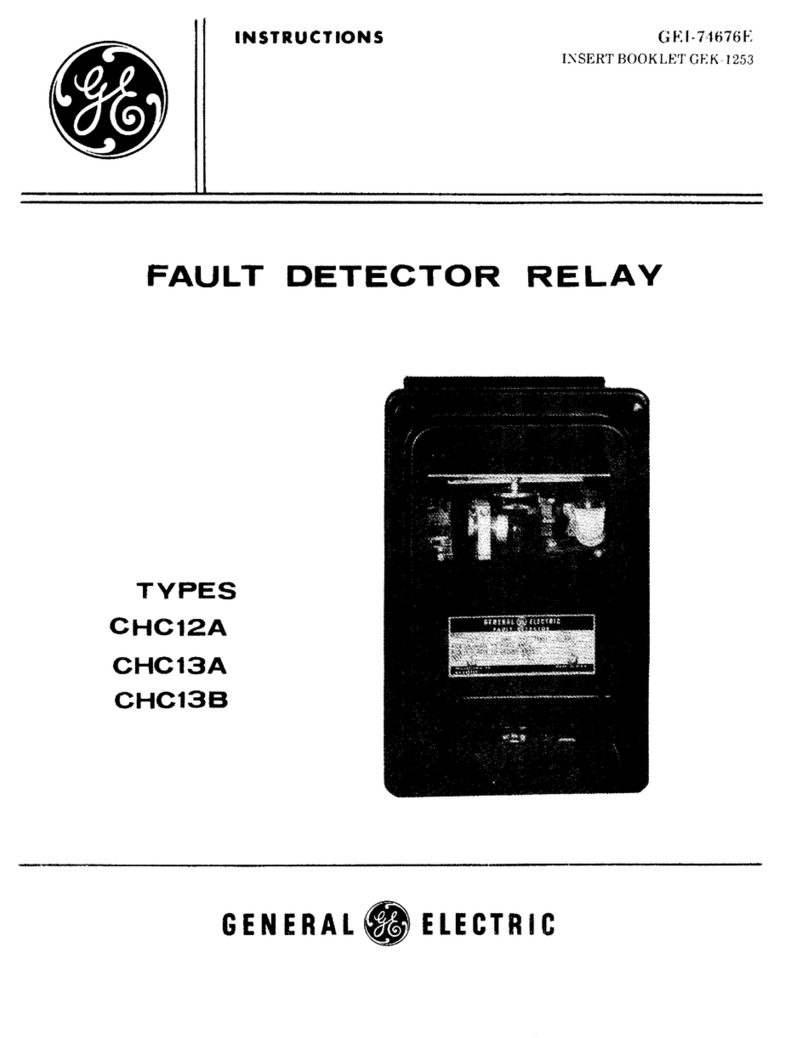
GE CLPG12C User manual

INSTRUCTIONS
CARRIER
CURRENT
GROUND
RELAY
CLPG12C
GENERAL
ELECTRIC
GEI-8391OG

GEI-83910
TABLE
OF
CONTENTS
PAGE
INTRODUCTION
........................
. . . . . . . . . . . . . . . . . . . . .
..
.......
3
APPLICATION
..............................
. . . . . . . . . . . . . 3
RATINGS
..........................
.........
4
COILS
.........
.......
...................................
4
CONTACTS
................
.......................................
4
CHARACTERISTICS
.........
. . . . . . . . . . . . . . . . . . . . . . . . . . . . . . . . . . . . . 5
OPERATING PRINCIPLES
....
. . . . . . . . . . . . . . . . . . . . . . . . . . . . . . . . . . 5
PiCKUP.................
..........................
......
........
5
OPERATING
TIME
...................................................
5
BURDEN
................
..........................................
5
CALCULATIONS
OF
SETTINGS
...............................................
5
TWO-TERMINAL
LINE
......................................................
6
THREE-TERMINAL
LINE.
. . . . . . . . . . . . . . . . . . . . . . . . . . . . . . . . . . . . . . . .
..
6
CONSTRUCTION
...............
. . . . . . . . . . . . . . . . . . . . . . . . . . . . . . . . . . . . . .
..
7
CARRIER-START UNIT (G-1)
.................................................
7
TRIP UNIT (G-2)
...........
. . . . . . . . . . . . . . . . . . . . . . .
..
..................
8
DIRECTIONAL UNIT (GD)
...................................................
8
AUXILIARY
UNIT (GD1X)
...................................................
8
SEAL-IN UNIT
(SI)
...................
. . . . . . . . . . . . . . . . . . . . . . 9
RECEIVING,
HANDLING,
AND
STORAGE
..
. . . . . . . . . . . . . . . . . . . . . . . . . . . . . . . . . .
..
9
ACCEPTANCE
TESTS
............................................................
9
VISUAL INSPECTION
................
. . . . . . . . . . . . . . . . . . . . . . . . . . . . . . . .
..
10
MECHANICAL
INSPECTION
................................................
10
ELECTRICAL
TESTS
........................................................
10
Upper-Unit
Pickup
(G1)
........................
...............
10
Middle-Unit
Pickup
(G2)
...........
. . . . . . . . . . . . . .
11
Bottom-Unit
Pickup
(GD)
...........
. . . . . . . . . . . . . . . . . . .
..
11
Bottom-Unit-Core
Check (GD)
.......
. . . . . . . . . . . . .
..
11
GD1X
Unit
Pickup
........................
. . . . . . . . . . . . . . . . . . . . .
..
11
INSTALLATION PROCEDURE
..........
.......................................
11
RELAY SETTINGS
..................
. . . . . . . . . . . . . . . . . . . . . . . . . . . . . . .
..
11
CARRIER-PICKUP-START UNIT (G1)
....
...................................
12
CLUTCH
ADJUSTMENT........
....................................
12
TRIP UNIT (G2)
..........................................................
12
CLUTCH ADJUSTMENT
....................................................
13
DIRECTIONAL UNIT (GD)
........................
. . . . . . . . . . . . . . . . .
..
13
PERIODIC
CHECKS
AND
ROUTINE
MAINTENANCE.
.
..
. . . . . . . . . . . . .
..
13
MECHANICAL
CH
ECKS
.............................
14
ELECTRICAL
TESTS
.............
. . . . . . . . . . . . . . . . . . . . . . . . . . . . . . . . . .
..
14
SERVICING
....................................................
. . . . .
..
14
MECHANICAL
ADJUSTMENTS
.......................................
14
ELECTRICAL ADJUSTMENTS . . . . . . . . . . . . . . . 15
RENEWAL
PARTS...
..........
......................................
16
LIST
OF
FIGURES......
........
..........................
17
(Cover
Photo
8029772)
)

GEI-83910
CARRIER
CURRENT
GROUND
RELAY
CLPG12C
I
NTRODUCTI
ON
The
CLPG12C
is
a high-speed, zero-sequence ground
relay
designed
specifically
for
use as a ground-fault
relay
in directional-comparison
relaying
schemes. This
relay
contains
one
high-speed zero-sequence
directional
unit,
which
may
be
po
1
ari
zed
from
voltage and/or
current.
It
also contains
two
hi
gh-speed
zero-
sequence non-directional overcurrent
units
and
one
direct-current-operated
(DC)
aux
il
iary
unit.
The
CLPG12C
is
packaged
ina
size-L2 case
and
incl udes a
target
and
a
separate
seal-in
unit.
One
CLPG12C
is
required per
terminal.
APPLICATION
The
CLPG12C
finds
application
on
grounded neutral systems as
the
directional-
comparison ground
relay
in directional-comparison schemes,
regardless
of
the type
of channel
that
is
used. This
relay,
operating in conjunction with the
pilot
channel
and
the
CLPG12C
relays
at
the
other
ends of the
protected
1ine
section,
provides high-speed
tripping
for
all
single-phase-to-ground
faults
in
the
protected
line
section.
The
two
non-di
rect
i
ona
1 overcurrent
uni
ts
and
the
operat
i
ng
ci
rcuit
of
the
directional
unit
may
be
all
supplied in
series
from
the
neutral
connection of
the
three
line-current
transformers.
The
polarizing
circuit
of
the
directional
unit
may
be
supplied
from
a
current
transformer in the neutral of a grounded
neutral
power
transformer or
from
the broken-delta secondary connection
of
three
potential
transformers
whose
primary windings
are
connected in
wye,
or
it
may
be
simultaneously supplied
from
both sources of
polarization.
These
instructions
do not
purport
to
cover
all
details
or
variations
in
equipment
nor
provide
{or
every
possible
contingency
to
be
met
in
connection
wilh
inst.allation, operation or
maintenance.
Should
{urther
in{ormation
be
desired
or
should
particular
problems
arise
which
are not covered
sufficiently
for
the
purchaser's
purposes,
the
matter
should
be
referred
to
the
General
Electric
Company.
To
the
ex/ent
required
the
products
described
herein
meet
applicable
ANSI,
IEEE
and
NEMA
standards;
bllt no
such
assurance
is
giuen
with
respect
to
local codes alld
ordinances
because
they
vary
greatly.

GEI-83910
The
sensitivity
of
each
of
the
overcurrent
units,
as
well
as
that
of
the
directional
unit,
is
adjustable
over
the
ranges
specified
under
RATINGS.
The
operating
times
of
the
three
units
are
given
in
the
CHARACTERISTICS
section.
!\
complete
elementary
diagram
for
a
directional-comparison
scheme
over
a
carrier
channel
including
the
CLPG12C
may
be
obtained
from
the
local
district
office.
Figure
2 shows
typical
external
connections.
RATINGS
The
potential
coils
of
the
CLPG12C
relay
are
rated
120
volts
intermittent
and
360
volts
for
10
seconds,
both
values
being
at
rated
frequency.
The
CLPG12C
relay
is
available
in
either
of
the
following
ratings
at
either
50
or
60 Hz.
Gl
Unit
G2
Unit
GD
Unit
GD
Unit
Range Range Range Range
in
in
V x I I x I
Amperes Amperes
Potential
Current
Polarization
Polarization
0.4
-
1.6
0.5
-
2/1
- 4
3.6
-
57.6
0.25
-
4.0
0.8
-
3.2
1 -
4/2
- 8
3.6
-
57.6
0.25
-
4.0
The
angle
of
maximum
torque
is
80" ±
2"
(I
lags
V)
when
the
unit
is
potential-
polarized.
If
it
is
current-polarized,
the
angle
of
maximum
torque
is
10" ± 10"
(I
pol
lead
lop).
If
the
unit
is
set
for
0.25
(IxI),
then
the
unit
will
pick
up
when
VxI
=
4.5
±
15%.
If
a
3.6
VA
pickup
is
required,
then
the
control
spring
should
be
adjusted
so
that
the
contact
will
just
close
when
3.6
VA
is
applied
at
the
angle
of
maximum
torque.
The
auxiliary-telephone-relay
unit
(GDIX)
is
available
in
continuous
ratings
of
48
or
110
or
125
or
250
vo
lts
DC.
The
current
ci
rcu
its
are
rated
3 amperes
I,
cont
i nuous and 140 amperes
for
one
second.
The
140 ampere
rat
i
ng
is
also
the
max
imum
permi
ss
ib1e
current.
The
target-and-sea
1-
in
coil
s
with
a one (1) ampere
rating
will
carry
30
amperes
for
tripping
duty
and
2.5
amperes
continuously.
The
target··and-seal-in
units
with
ratings
of
0.6
ampere
DC
wi
11
carry
30
amperes
for
tripping
duty
and
0.9
amperes
continuously.
CONTACTS
The
tripping
contacts
of
this
relay
are
the
normally-open
contacts
of
the
G2
and
GD
units.
They
wi
11
carry
2.5
amperes
cont
i nuous
ly
and
wi
11
c1
Dse
and
carry
30
amperes
DC
for
tripping
duty
at
control
voltages
of
250
VDC
or
less.
The
breaker-
trip-coil
circuit
should,
however, always
be
opened
by
a
circuit-breaker
auxi
liary
switch
or'
other
suitable
means.
If
the
tripping
cUlTent
exceeds
30
amperes,
,in
auxi
liary
tripping
y'eliJy
should
be
used.
,

GEI-83910
CHARACTERISTICS
OPERATING
PRINCIPLES
The
three
main
units
of the
CLPG12C
relay are of the high-speed
efficient
eight-pole
cup
structure.
They
most
closely resemble
an
induction motor, except
that
the
rotor
iron
is
stationary
whi
1e the
rotor
conductor
port
i
on
(the cup)
is
free
to
rotate.
PICKUP
The
relays can
be
set
to
pick up,
i.e.
close the
N.O.
Contacts,
at
the values
of
current
shown
in the
RATINGS
section.
The
method
of
adjusting
pickup
is
described in the
INSTALLATION
PROCEDURE
section.
OPERATING
TIME
Figure 3
shows
the operating time of the
two
overcurrent
units
(Gl
and
G2)
as
a function of operating
current.
Figure 4
shows
the operating time of
the
directional
unit
(GO)
as a function of multiples of product pickup.
TABLE
I
60
C.P.S.
CURRENT
BURDENS
AT
MINIMUM
Gl
PICKUP
MEASURED
BURDENS
IN
OHMS
IMPEDANCE
AT:
Gl
Transformer
Gl
G2
Tap
R X Z 5
10
20
60
Circuit
Connection Rating
Range
Ohms Ohms
Ohms
Amps Amps
Amps
Amps
Amps
Amps
Operating Shunt
0.4-1.6
0.5-2 0.80 1.84 2.00 2.00 1.80 1.50 0.95
(Studs 3-4) Shunt
0.4-1.6
1 - 4 0.60 1.36 1.
50
1.50 1.20 1.00 0.70
Stepup
0.4-1.6
0.5-2 2.44 3.42 4.20 4.20 3.10 2.20 1.20
Stepup
0.4-1.6
1 - 4 2.12 3.12 3.80 3.80 2.60 2.00 1.10
Shunt
0.8-3.2
1 - 4 0.30 0.70 0.76 0.76 0.70 0.57 0.40
Shunt
0.8-3.2
2 - 8 0.23 0.52 0.58 0.58 0.50 0.42 0.31
Stepup
0.8-3.2
1 - 4 0.73 1.04 1.26 1.26 1.20 1.05 0.75
Stepup
0.8-3.2
2 - 8 0.64 0.94 1.14 1.14 1.00 0.80 0.50
Polarizing
All
All All 0.25 0.04 0.26 0.26 0.23 0.21 0.20
(Studs 5-6)
8URDEN
The
burdens
imposed
on
the current transformers are
shown
in Table
I.
The
capacitive
potential
circuit
burden, calculated
at
120
volts,
60
Hz,
is
shown
in
the
following
table:
Potential
Circuit
Burdens
WATTS
VARS
VOLT
AMPERES
18
3.18 18.35

The
burdens
imposed
by
the
for
the
comparable
60
Hz
relays.
given
in
the
following
table:
DEVICE
UNIT
Target
Seal-In
Target
Seal-In
GEI-83910
50
Hz
relays
are
approximately
90%
of
those
shown
The
resistance
of
the
target
and
seal-in
units
is
RATING
RES.
25°C
1 A
0.34
Ohms
1 A
0.28
Ohms
0.6A
0.73
Ohms
0.6A
0.72
Ohms
___
----.:_~
___
:...:....
__
---------.J
CALCULATIONS
OF
SEITINGS
It
is
cond
it
ions.
follows:
not
possible
to
give
specific
settings
for
the
CLPG12C
relay
for
all
However, a
general
guide
for
setting
the
three
units
of
this
relay
TWO-TERMINAL
LINE
GO
UNIT:
Set
for
minimum
pickup
(maximum
sensitivity).
Check
to
ensure
pickup
for
all
si
ngl
e-phase-to-ground
fau
lts
on
the
protected
1i ne
with
1ine
breakers
closed
at
both
terminals.
Use
dual
polarization
where
facilities
permit.
Gl
UNIT:
The
preferred
pickup
setting
is
the
minimum
rated
pickup
value
of
this
unit.
Do
not
set
higher
than
80%
of
the
G2
pickup
setting
at
the
remote
end
of
the
line.
t)
G2
UNIT:
Set
pickup
no
higher
than
67%
of
minimum
single-phase-to-ground
fault
current
in
the
relay
with
the
remote
breaker
closed.
Lower
pickup
settings
are
permissible,
and
in
most
cases
desirable
for
increased
speed
of
operation.
However,
do
not
set
pickup
lower
than
125%
of
the
Gl
pickup
setting
at
the
remote
end
of
the
1
ine.
THREE-TERMINAL
LINE
GO
UNIT:
Set
for
minimum
pickup
(maximum
sensitivity).
Check
to
ensure
pickup
for
all
si
ngle-phase-to-ground
faults
on
the
protected
1i
ne
with
the
1i ne
breakers
closed
at
all
three
terminals.
Use
dual
polarization
where
facilities
permit.
Gl
UNIT:
The
preferred
pickup
setting
is
the
minimum
rated
pickup
value
of
this
unit.
However, when
current
outfeed
can
exist
for
internal
faults,
an
attempt
should
be
made
to
set
the
pickup
above
the
value
of
outfeeding
current
at
that
terminal.
In any
event
this
unit
should
not
be
set
higher
than
40%
of
the
G2
pickup
settings
at
the
two
remote
terminals.
\i~_~lnI:
Set
pickup
no
higher
than
67%
of
the
minimum
single-phase-to-ground
fault
current
in
the
relay
with
both
rl~mote
line
breakers
closed.
Lower
pickup
settings
are
permissible,
and in most Cilses
desirable
for
increased
speed
of
operation.
However,
do
not
set
pickup
lowey'
than
250%
of
the
Gl
pickup
settings
at
the
two
remote
terminals.
6

GEI-8391O
CONSTRUCTION
The
three
main
units
(G1,
G2,
and
GO)
of
the
elPG12e
relay
covered
by
these
instructions
are
of
the
induction-cup
construction.
This
is
the
top
unit
of
the
eLPG12e
relay.
It
has
two
electrically
separate
contacts.
The
right-hand
(front
view)
contact
is
closed
when
the
unit
is
de-
energized.
When
energized,
the
unit
operates
to
open
its
right-hand
contact
and
then
closes
its
left-hand
contact.
The
four
corner
coils
of
the
unit
consist
of
two
windings
each.
The
inner
windings
consist
of
a
large
number
of
turns
of
fine
wire,
and
the
outer
windings
have a
few
turns
of
heavy
wire.
The
inner
windings
are
connected
in
series
with
a
capacitor
to
form a
phase-shift
i
ng
ci
rcu
it.
The
outer
wi
nd
i ngs
are
connected
in
series
internally,
and
into
the
operating-current
circuit
externally.
The
four
side
coils
are
similarly
connected
into
the
operating-current
circuit.
To
increase
the
torque
output
for
sensitive
settings
of
the
Gl
unit
(1-2
times
minimum
pickup),
there
is
provided
in
the
elPG12C
relay
a
2:1
autotransformer.
The
transformer,
when
connected
as
a
step-up
transformer,
effectively
doubles
the
current
in
the
G1
unit.
The
increased
torque
thus
requires
additional
control-spring
windup,
thereby
i
ncreas
i
ng
the
force
on
the
norma
lly-c
lased
(carri
er-start)
contact.
The
net
result
is
to
reduce
or
eliminate
the
possibility
of
spurious
carrier
signals
due
to
shock
or
vibration
when
sensitive
settings
are
employed
on
this
unit.
As
a
further
aid
in
reducing
the
possibility
of
spurious
carrier
signals,
the
carrier-start
contact
is
of
the
low-gradient
construction.
The
low-gradient
contacts
of
the
Gl
unit
are
shown
in
Figure
5.
Both
the
stationary
and
the
moving
contact
brushes
are
made
from
low-gradient
material.
When
subjected
to
vibration
they
tend
to
follow
one
another,
thus
resisting
contact
separation.
The
contact
di a1
(A)
supports
the
stat
ionary
contact
brush (B) on
whi
ch
is
mounted a
conical
contact
tip
(e).
The
moving-contact
arm
(0)
supports
the
moving-
contact
brush (E) on which
is
mounted a
button
contact
tip
(F).
The
end
of
the
moving-contact
brush
bears
against
the
inner
face
of
the
moving-contact-brush
retainer
(G).
Similarly,
the
end
of
the
stationary-contact
brush
bears
against
the
inner
face
of
the
stationary-contact-brush
retainer
(H).
The
stop
(J),
mounted on
the
contact
dial,
functions
to
stop
the
motion
of
the
contact
arm
by
striking
the
moving-contact-brush
retainer
after
the
moving- and
stationary-contact
members have
made
contact.
The
stationary-contact
support
(K)
and
the
contact
dial
are
assembled
together
by
means
of
a mounting screw
(l)
and
two
locknuts
(M).
The
normally-open
contact
is
of
the
standard
barrel
type
of
construction.
The
barrel-type
contacts
shown
in
Figure
6
are
especially
constructed
to
suppress
bouncing.
The
stationary
contact
(G)
is
mounted
on
a
flat
spiral
spring
(F) backed
up
by
a
thin
diaphragm
(e).
These
are
both mounted
in
a
slightly
inclined
tube
(A). A
stainless
steel
ball
(8)
is
placed
in
the
tube
before
the
diaphragm
is
assembled.
When
the
moving
contact
hits
the
stationary
contact,
the
energy
of
the
former
is
imparted
to
the
1
atter
and
thence
to
the
ball,
whi
cn
is

GEI-83910
free
to
roll
up
the
inc1
ined tube. Thus, the
moving
contact
comes
to
rest
with
substantially
no
rebound or
vibration.
The
moving
contacts are supported
on
a
molded
plastic
arm
that
is
attached
to
the
rotor
shaft.
The
arm
is
held
from
rotating
freely
by
a control spring. This
spring maintains a torque in the
direction
to hold the normally-open
contacts
open
by
a magnitude
that
determines the pickup of the
unit.
B.
TRIP
UNIT
(G-2)
This
is
the middle
unit
of the
CLPG
relay
and
is
similar
in
construction
to
the
Gl
unit
previously described. This
unit
has
two
electrically
separate
contacts.
The
1eft-hand contact
is
closed
when
the
unit
is
de-energized.
When
energized, the
unit
operates
to
open
its
1eft-hand contact
and
then
closes
its
right-hand
contact.
It
further
differs
from
the
Gl
unit
as
follows: -
The
Gl
unit
has
its
corner
coils
and
side
coils
connected in
series
internally.
However,
the
G2
unit
side-
and
corner-coil
connections are brought out
to
a tap block located
at
the side of the
G2
unit.
This tap block arrangement
permits the
G2
unit
coils
to
be
connected in
series
or
parallel,
depending
on
the
tap chosen. This allows the
unit
to
have
two
ranges of pickup.
Both
the normally-open
and
normally-closed contacts of the
G2
unit
are of
the
barre1-type
construct
ion previ
ous1
y described. Furthermore the
G2
unit
does not
use
an
auxiliary
current
transformer.
C.
DIRECTIONAL
UNIT
(GO)
This
is
the bottom
unit
of the
CLPG
relay.
It
has
2
electrically
separate
contacts
of the
barrel-type
constructi
on
previous
1y
described.
When
de-energized,
the right-hand contact
is
closed.
When
energized in the
tripping
direction,
the
unit
operates
to
open
the right-hand contact
and
then closes the left-hand
contact.
The
stator
has
eight
1
ami
nated
magnet
ic
po
1es
project
i
ng
inward
and
arranged
symmetrically around a
central
magnetic core.
The
poles are
fitted
with
current
and
potential
coils.
Three of the corner
coils
are connected
internally
to
form
a
single
circuit
for
current
polarization.
Each
of these
coils
has
two
windings,
one
of which
carries
the polarizing current.
The
other
winding
is
connected in
series
with the corresponding winding of each of the
other
two
coils,
with a
capacitor.
The
resultant
flux
from
these
coils
is
shifted
in phase with
respect
to
the
operating-circuit
flux.
The
fourth corner
coil
is
a
potential
coil
for
potential
polarization.
The
four side
coils
are connected together to
form
the
operating-
current
circuit.
In
the annular
air
gap
between
the poles
and
central
core
is
the
cylindrical
cup-like
part
of the
aluminum
rotor,
which
turns
freely
in the gap.
The
rotor
shaft
is
supported
at
the bottom
by
a
steel
pivot
that
projects
downward
through a
bronze guide beari
ng
mounted
in the
end
of the
shaft.
The
shaft
carri
es the
movable contact
arm
through
which
the contact
circuits
are completed.
D.
AUXILIARY
UNIL.0DIX)
This
unit
is
located in the rear of the
CLPG12C
relay,
just
below
the upper
unit.

GEI-83910
It
is
a telephone-type
relay
unit
with
adjustable
time--delay pickup.
T[,e
unit
is preset at thf'
factory
for
16-18 milliseconds time--delay pickup.
f\
copper slug
on
the armatli,-e
end
of the core delays the flux buildup,
and
consequently the
relay
I,ickup.
DrolJOut
time
is
approximately
88
milliseconds.
One
normally-closed
contact
and
OIIC normally-open contact
of
the
unit
are brought out
to
separate
studs
fOl"
external
cir'cuH
control.
The
resistor',
R?,
is
connected dcross the
GOIX
coil
when
it
is
used
on
220
or
250
VDC.
E.
SEAL-IN
UNIT
(SI)
This
unit
is
located in the upper right-hand corner
(rear
view) of the
relay.
It
is
of the
familiar
hinged-armature
construction
and
operates
to
lift
and
close
its
contacts,
whenever
sufficient
trip
current
flows in
its
operating
coil.
The
above
units
and
associated
components are
mounted
on
a
steel
cradle
assembly
that
can
be
easily
removed
from
the
relay
case.
The
crad1e
is
locked in the case
by
means
of 1atches
at
the
top
and
bottom.
The
electrical
connections between the case block
and
cradle
block are completed
through a removable connection plug. A
separate
testing
plug can
be
inserted
in
p
Iace of
the
connecti
on
plug to permit
test
i
ng
the re1
ay
in
its
case.
The
cover
attaches
to
the case
from
the
front
and
includes the
target
reset
mechanism
and
an
interlock
arm
to prevent the cover
from
being replaced
until
the connection plug
has been
inserted.
The
case
is
suitable
for
either
semi
flush or surface mounting
on
panels
up
to
two
inches (2")
thick.
Hardware
is
available
for
any
panel
thickness
up
to
two
inches,
but panel thickness
must
be
specified
on
the
order
to
ensure
that
the
proper hardware
will
be
provided. Outline
and
panel-drilling
dimensions are
shown
in Figure 14.
RECEIVING,
HANDLING,
AND
STORAGE
These re1ays,
when
not inc1
uded
as
part
of a contro1 pane1,
wi
11
be
shi
pped
in
cartons
designed
to
protect
them
against
damage.
Immediately
upon
receipt
of
a
relay,
examine
it
for
any
damage
sustained in
transit.
If
injury
or
damage
resulting
from
rough handling
is
evident,
file
a
damage
claim
at
once with
the
transportation
company
and
promptly
notify
the
nearest
General
Electric
Sales
Office.
Reasonable care should
be
exercised in unpacking the
relay
in
order
that
none
of the
parts
are
injured
nor the adjustments
disturbed.
If
the
relays
are not to
be
installed
immediately, they should
be
stored
in
their
original
cartons
in a place
that
is
free
from
moisture,
dust,
and
metal 1
ic
chips.
Foreign
matter
collected
on
the
outside
of the case
may
find
its
way
inside
when
the cover
is
removed,
and
cause
trouble
in the
operation
of the
relay.
Q

GEI-83910
ACCEPTANCE
TESTS
Immediately
upon
receipt
of the
relay,
an
examination
and
tests
should
be
made
to
make
sure
that
no
damage
has
been
sustained in shipment
and
that
the relay
calibrations
have
not
been
disturbed.
If
the examination or
tests
indicate
that
readjustment
is
necessary,
refer
to
the section
on
SERVICING.
VISUAL
INSPECTION
Check
the nameplate to
make
sure
that
the
model
number,
rating
and
calibration
range of the
relay
recei
ved
agree with the requ i
sit
ion.
Remove
the re1
ay
from
its
case
and
check
that
there are
no
broken or cracked
molded
or
compound
parts,
and
that
all
screws are
tight.
MECHANICAL
INSPECTION
It
is
recommended
that
the following mechanical adjustments
be
checked:
1. There should
be
no
noticeable
friction
in the
rotating
structure
of each
unit.
The
normally-closed contacts should
be
closed
when
the
relay
is in
an
upright
position.
2. There should
be
an
end
play of
from
.005
to
.015 inch
on
the
shafts
of the
rotat
i
ng
structures.
The
lower
jewe
l-screw beari
ng
of each
unit
should
be
screwed firmly in place,
and
the pivot
at
the top of the
shaft
should
be
locked
by
its
set
screw.
3.
The
contact
gap
on
each
unit
should
be
approximately 0.020 inches.
4.
The
target
shield
should drop
freely
when
the armature
is
pushed
against
the
pole piece.
With
the cover fastened securely in place, check
that
the
target
resets
positively
when
the
reset
button
at
the bottom of the cover
is
operated.
5.
The
armature
and
contacts of the
seal-in
unit
should
move
freely
when
operated
by
hand. There should
be
at
least
1/32"
wipe
on
the
seal-in
contacts.
6.
Check
the
location
of the contact brushes
on
the cradle
and
case blocks
against
the internal-connection diagram for the relay
(See
Figure 13).
Be
sure
that
the shorting bars are in the proper locations
on
the case blocks,
and
that
the long
and
short brushes
on
the cradle block agree with the
internal-connection
diagram. Figure 8
shows
a sectional
view
of the case
and
cradl
e blocks with the connecti
on
plug in place.
Note
that
there
is
an
auxiliary
brush in each position
on
the case block. This brush should
be
formed high
enough
so
that
when
the connecting
plug
is
inserted,
it
engages
the
auxiliary
brush before
striking
the
main
brush. This
is
especially
important in current
circuits
and
other
circuits
with shorting bars, since
an
improper adjustment of the
auxiliary
brush could
result
in a
CT
secondary
circuit
being momentarily open-circuited.
ELECTRICAL
TESTS
Upper-Unit
Pick~~
Check
that
the green lead
is
connected to terminal
#3
and
that
the black lead
is
connected to terminal
#3A.
See
internal diagram Figure
13.
10

GEI-83910
Usinq
the
test
connections
shown in
Figure
9,
the
unit
should
pick
up
and
close
the
normally~~open
(left)
contacts
<it
a
value
of
current!:
'J%
of
trw
minimulil
',;h,wiI1
on
the
nameplate
for
thi';
unit,
A neon
light
is
Y"(;comm('nriecJ
to
indicttU;
contitct.
CiOSIll'P,
and
the
GD
unit
must be
held
in
the
normally-closed
I'0.,ition
Lu
obtain
irldication
of
G1
contact
closure
(see
Figures
9 and
13).
With
the
tap
plugs
in
the
lower
tap
range,
and
using
the
connections
shown
in
Figure
9,
the
unit
should
pick
up
(close
the
right-hand
contacts)
at
a
value
±
5%
of
the
minimum
value
shown on
the
nameplate
for
this
unit.
Bottom-Unit
Pickup
(GD)
Using
the
test
connections
shown
in
Figure
9,
the
unit
should
pick
up
(close
the
left-hand
contacts)
at
0.5
ampere
±5%.
Bottom-Unit-Core
Check
(GD)
a.
Check
the
position
of
the
notch
that
indicates
the
position
of
the
flat
on
the
core.
This
notch
should
be
pOinting
to
the
front
right-hand
corner
of
the
unit,
front
view.
b.
Short
ci
rcu
it
termi
na1s 7 and
8;
connect
the
re
1ay
as
shown
in
part
A
of
Figure
11.
c.
Adjust
10
operate.
operate.
for
0.25
amp
and Ip
for
100
amps
and
check
that
the
unit
does
not
If
the
unit
operates,
adjust
the
core
until,
the
unit
does
not
NOTE:
DO
NOT
KEEP
THE
100
AMPS
ON
THE
CIRCUIT
FOR MORE
TIME
THAN
NECESSARY,
TO AVOID OVERHEATING
THE
COILS.
d.
Open
the
polarizing
circuit,
adjust
10
for
7 amps, and
check
that
the
unit
does
not
operate.
If
the
unit
operates,
adjust
the
core
for
no
operation
and
repeat
the
test,
starting
at
b.
e.
Unshort
terminals
7 and 8 and
connect
as
shown
in
part
B
of
Figure
11.
f.
Set
10
for
0.25 amperes and
Vp
for
120
volts,
and
check
that
the
unit
does
not
operate.
If
the
unit
operates,
adjust
the
core
for
no
operation
and
repeat
the
tests,
starting
at
b.
GD1X
Unit
Pickup
USing
the
test
connections
shown
in
Figure
10,
the
unit
should
pick
up
at
a
value
of
80%
or
less
of
the
voltage
shown
on
the
nameplate.
The
G1
normally-open
contact
must be
held
closed
during
this
test
(see
Figures
10
and
13).
11

GEI-83910
INSTALLATION
PROCEDURE
If
after
the
ACCEPTANCE
TESTS
the relay
is
held in storage before shipment
to
the job
site,
it
is
recommended
that
the visual
and
mechanical inspection described
under the
section
on
ACCEPTANCE
TESTS
be
repeated before
instanation.
Before
any
of the following
electrical
adjustments are
made,
the
relay
should
be
in
its
case,
preferably
mounted
in
its
permanent location.
RELAY
SETTINGS
Refer
to
the
section
on
CALCULATIONS
OF
SETTINGS
for a discussion of suggested
procedures for determining the
settings
of the
three
main
units.
CARRIER-PICKUP-START
UNIT
(GIl
If
the
required
setting
is
less
than
two
times the
mlnlmum
value
shown
on
the
namep
1
ate,
the
Gl
aux
il
iary current transformer
shou
1d
be
connected in such a
way
as
to
step
up
(The
green lead connected
to
terminal
#3
and
the black lead connected
to
terminal
#3A).
Should the required
setting
be
greater
than
two
times the
minimum
value
shown
on
the nameplate, interchange the green
and
black
leads.
Using
the
test
connections
shown
in Figure
9,
apply the desired current
to
the
relay.
Loosen
the hexagonal locking screw located
at
the
rear
of the
spiral-spring
assembly.
Then
slip
the adjusting ring (to
which
the control spring
is
attached)
in
the
ring
guide in a
direction
that
will cause the normally-open
contacts
barely
to
close
at
the pickup level chosen. Retighten the locking screw
and
recheck the
settings.
CLUTCH
ADJUSTMENT
USing
the
test
connections
shown
in Figure
9,
and
referring
to
Table
II,
check
that
the
clutch
slips
(i.e.
the induction
cup
begins
to
rotate
after
the normally-
open contact
has
closed) within the
prescri
bed
1
imits.
To
prevent overheati
ng
the
relay,
a suggested
method
for determining
that
the clutch
slips
within the
prescribed
limits
is
to
apply current
5%
below
the
minimum
shown
in the
table
and
note
that
the clutch does not
slip.
Next
apply
current
5%
above
the
maximum
shown
in the
table
and
note
that
the clutch does
slip.
Unit
Gl
t
G2
GO
TABLE
II
CLUTCH
ADJUSTMENTS
Current Rating,
Amps
0.4
-
1.6
0.8
3.2
0.5
2.0
1.0 4.0
0.25 4.0
Product Pickup
Clutch
Slips,
Amps
3.5
-
5.0
7.0 -10.0
7.5 -10.0
15.0 -20.0
10.0 -15.0
t Values of clutch
slip
are primary
amperes
with the
auxiliary
current
transformer not connected
for
step
up.
12

GEI-83910
TRIP
UNIT
(G2)
Pickup:
Connect
the taps in the
G2
tap block
so
that
the desired
setting
will
be
within the selected tap range.
Should
the desired
setting
be
such
that
either
tap
range
would
be
adequate,
it
is
recommended
that
the lower tap range
be
used
on
two-
terminal
lines
and
the higher tap range
be
used
on
three-terminal
lines.
Using
the
test
connections
shown
in Figure
9,
apply the desired level of current
to
the relay
and
set
pickup
by
means
of the control-spring adjustment,
as
previously described
for
the
G1
unit.
G2
Unit
Rebound
Test:
Connect
the
relay
as
shown
in Figure 7,
and
check
that
the G2-unit contact
wi
11
not
rebound
on
the
removal
of
an
external
fault.
The
test
connections
show
the
TB
unit
of the
NAA22A
being
used
for
this
test
but
if
an
instantaneous dropout
relay
is
available
it
may
be
substituted.
The
use of the
TB
unit
will
result
in
loss of instantaneous reclosure in the
carri
er-current
scheme,
and
the
TB
unit
contact in
circuit
15-16
must
be
shorted
so
that
protection
is
still
provided.
The
following
test
procedure should
be
followed.
1. Close the
G2
unit
manually to
check
that
the
lamp
will
light.
2. Manually close the
TB
unit
and
apply
maximum
expected through-fault
current
to
the
G2
unit.
3.
Remove
the current
and
check
that
the
lamp
does
not
light.
CAUTION:
It
is
advisable
to
practice
this
sequence,
so
that
the
tester
will
be
able
to
operate
it
correctly
with a high-current impulse
short
enough
to
avoid overheating the
unit.
If
the
G2
unit
fails
this
test,
check
the
wipe
and
gap
of the
G2
barrel contacts,
and
also the clutch
slip
adjustment.
CLUTCH
ADJUSTMENT
Using
the
test
connections
shown
in Figure 9
and
the appropriate value
shown
in Table
II,
check
the clutch adjustment as previously described
for
the
Gl
unit.
DIRECTIONAL
UNIT
(GO)
Current-Polarized Pickup:
Using
the
test
connections
shown
in Figure
9,
apply
the desired level of current to the relay
and
set
pickup
by
means
of the control-
spring adjustment,
as
previously described for the
G1
unit.
The
product pickup
thus obtained will
be
the square of the current
app
1i
ed
to the
relay.
Thus,
if
a
product pickup of 0.25
ampere
is
desired, 0.5
ampere
should
be
applied
to
the
relay.
Potential-Polarized Pickup:
Using
the
test
connections
shown
in Figure 12, the
GO
unit
can
be
set
for potential
polarization.
When
setting
pickup
for
potential
polarization,
it
is
recommended
that
a voltage
(Vp)
of 5 to
30
volts
be
used. Five
volts
is
the
minimum
value encountered in
ground
relaying, while
above
30
volts
the
current
is
small
and
difficult
to measure.
Clutch Adjustment:
Using
the
test
connections
shown
in Figure 9
and
the
appropriate value
from
Table
II,
the clutch
may
now
be
set
as
previously described
for
the
G1
unit.
13

GEI-83910
GDIX
Unit Pickup:
Using
the
test
connections
shown
in Figure 10, the
unit
should pick
up
at
80%
or
less
of the
DC
voltage
shown
on
the nameplate.
With
rated
voltage suddenly
applied,
the
unit
should pick
up
in 16-18 milliseconds.
PERIODIC
CHECKS
AND
ROUTINE
MAINTENANCE
In
vi
ew
of
the
vital
role
of
protecti
ve
re1
ays
in the operati
on
of a
power
system
it
is
important
that
a periodic
test
program
be
followed.
It
is
recognized
that
the
interva1 between periodi c checks
wi
11
vary dependi
ng
upon
envi ronment,
type of
relay,
and
the
user's
experience with periodic
testing.
Until the user
has
accumulated
enough
experience to
select
the
test
interval
best suited to his
individual requirements
it
is
suggested
that
the
following points
be
checked
once
a
year.
MECHANICAL
CHECKS
Operate the contacts
by
hand
and
check
that
the contacts are
making
with
proper wipe.
The
barrel-type
contacts are
marked
with a
letter
on
the
rear
of the
barrel
that
designates the
amount
of wipe.
Unit Contact Stamping
Wipe
Top
Left H .013-.018
Middle Left L .002-.004
Middle Right L .002-.004
Bottom
Right L .002-.004
Bottom
Left S .004-.009
The
wipe
is
the
distance the
spiral
contact can
move
into
the
barrel
before
it
hits
the diaphragm, as
shown
in Figure 6. This
can
be
changed
by
adjusting the
flat
spiral
spring
until
the proper spacing
is
obtained.
Examine
the
contact surfaces
for
signs of
tarnishing
or corrosion. Fine
silver
contacts should
be
cleaned with a burnishing tool
that
consists
of a
flexible
strip
of metal with
an
etch-roughened
surface.
Burnishing
tools
designed
especially
for
cleaning
relay
contacts
can
be
obtained
from
the
factory.
Do
not
use knives,
files,
abrasive paper or cloth of
any
kind to clean
relay
contacts.
When
burnishing the low-gradient
G1
unit
contacts,
exercise additional caution
to avoid
damaging
the
delicate
leaf
springs to
which
the contacts are fastened.
ELECTRICAL
TESTS
Connect the
relay
as
shown
in Figure 9
and
check
that
the
pi
ckup
of the
G1
unit
is
within
±5%
of the
original
setting.
Next
check
that
the clutch
setting
is
within
±5%
of
the
original
setting.
Repeat the
tests
for
the
G2
and
GO
units,
using
the
test
diagrams
as
shown
in Figure 9.
Connect the
relay
as
shown
in Figure
10
and
check
that
the pickup of the
GD1X
unit
is
within
±5%
of the
original
pickup voltage.
14

GEI-83910
SERVICING
If
any
of the mechanical or
electrical
check points described in the previous
sections are
found
to
be
out of
limits,
the following points should
be
observed in
restoring
them.
MECHANICAL
ADJUSTMENTS
1. Gl-unit low-gradient (right-hand) contact adjustment:
a.
With
the
relay
setting
upright,
and
the
moving
contact
held
away
from
the
stationary
contact,
both the
stationary-contact
brush
and
the
moving-
contact brush should touch
their
respective
retainers
(See Figure
5).
b.
With
the
relay
lying
on
its
right
side
and
the
moving
contact held
clear,
the
stationary-contact
brush should
just
part
from
its
retainer
under
its
own
weight.
c.
With
the
relay
lying
on
its
left
side
and
the
moving
contact held
clear,
the moving-contact brush should
just
part
from
its
retainer
under
its
own
weight.
d.
With
the
relay
vertical
and
de-energized, the contacts should
make
with
(0.003-0.005 inch)
deflection
on
each brush
from
its
own
retainer.
To
adjust the contact
wipe
proceed as follows:
Adjust the stop screw in the face of the
stationary
contact
so
that
the
contact
tips
just
separate,
and
then
back
it
off
1/2
turn.
e.
The
gap
on
the normally-open contact should
be
between
15
and
20
mils,
which
can
be
achieved as follows:
Adjust the
left
contact barrel
until
the contacts
just
part,
and
then
back
the barrel
off
1/2
to
2/3 of a
turn.
2. G2-unit contact adjustment.
a.
With
the
unit
completely de-energized,
adjust
the control spring
so
that
the
center
line
of the
moving
contact
arm
is
parallel
to
the sides of the
relay.
b.
Using
a
neon
light
as
an
indication of contact
closure,
turn both contact
barrels
into the
moving
contact
until
they
just
touch.
c.
Lock
the
left
barrel in place
by
means
of the clamping screw.
d. Rotate the
right
barrel approximately 210·
to
obtain the 0.015-0.020 gap.
e.
Lock
the
right
barrel in place.
3. GO-unit contact adjustment.
a.
The
GD
unit
adjustment
is
similar
to the
G2
unit
previously described,
except the
right
barrel
is
locked in place
and
the
left
barrel
is
rotated
to obtain the 0.015-0.020 inch contact gap.
15

GEI-83910
4.
Shaft
End
Play:
The
end
play
of
the
shafts
of
the
three
main
units
should
be
1/64".
This can be
adjusted
by
the
position
of
the
upper
pivot.
Be
sure
to
tighten
the
set
screw
that
holds
the
upper
pivot
in
position
after
the
adjustment
is
completed.
5.
Barrel
Contact
Wipe
Check and Adjustment:
To
check
for
the
proper
amount
of
contact
wipe,
first
loosen
the
screw
that
locks
the
barrel
contact
in
its
mounti
ng
block so
that
the
barrel
contact
can
be
threaded
in
and
out.
Next
hold
the
moving
contact
still.
In
the
top
unit,
do
this
by
using
the
stop
screw
of
the
low-gradient
contact.
In
the
middle and bottom
units,
do
this
by
pushing
the
moving
contact
against
the
other
barrel.
Now
thread
the
barrel
contact
until
its
silver
contact
tip
just
touches
the
moving
contact.
Use
a
neon 1i
ght
as an i
nd
i
cat
i
on
of
contact
closure.
Conti nue
to
thread
the
contact
barrel
until
the
back
of
the
contact
touches
the
diaphragm behind
it
(See
Figure
6)
The
point
at
which
this
occurs
can
only
be
determined
by
feel.
CAUTION:
Do
not
thread
the
barrel
past
the
point
where
the
contact
first
touches
the
diaphragm;
further
threading
of
the
barrel
could
damage
the
diaphragm.
The number
of
degrees
of
contact
barrel
rotation
between
when
the
silver
contact
tip
just
touches
the
moving
contact
and
when
the
back
of
the
contact
touches
the
di
aphragm behi
nd
it
determi
nes
the
contact
wipe.
Rotating
the
barrel
45°
corresponds
to
a
0.004
wipe,
while
105°
corresponds
to
a 0.009
wipe.
If
the
proper
wipe
is
not
noted,
then
the
spiral
spring
upon which
the
contact
tip
is
fastened
must
be
re-formed.
Remove
the
contact
barrel
from
the
mounti
ng
block
and
remove
the
threaded
cap.
Lift
off
the
spi
ra
1
contact
assembly.
Holding
the
outer
edge
of
the
spiral
with
your
fingers,
place
a
tweezer
on
the
inside
of
the
spiral
next
to
the
contact
cone.
If
more wipe
is
reqUired,
then
lift
the
inside
spiral
so
that
the
contact
tip
is
stretched
away
from
the
diaphragm.
If
less
wipe
is
required,
then
the
spiral
should be
stretched
so as
to
move
the
contact
tip
toward
the
diaphragm.
Make
sure
that
the
spiral
is
not
distorted
or
bent
during
this
process.
Replace
the
spiral
contact
assembly
on
the
barrel
and screw
the
cap
onto
the
barrel.
The
wi
pe
should
now
be
re-checked
by
following
the
above
procedure.
It
may
be
necessary
to
repeat
the
wipe
adjustment
until
the
proper
wipe
is
obtained.
To
finish
the
procedure.
set
the
proper
contact
gap.
ELECTRICAL
ADJUSTMENTS
Clutch
Adjustment:
The
clutch
is
adjusted
by
means
of
the
screw
located
on
the
right-hand
side
of
the
moving
support.
See
Figure
1
for
location
of
this
screw.
To
readjust
the
clutch,
first
loosen
the
hexagonal
locking
nut
on
the
adjusti
ng
screw. Turni
ng
the
screw
into
the
shaft
(cl
ockwi
se
rotati
on
of
the
screw)
increases
the
value
of
current
necessary
to
cause
the
clutch
to
slip.
On
the
G2
unit
it
is
recommended
that
the
clutch
adjustment
be
made
with
the
taps
in
the
lower
tap
range.
GDIX
Pickup:
To
change
the
pickup time
or
voltage
of
the
GDIX
unit,
resistor
Rl
is
adjusted
(see
Figure
IB).
Increasing
Rl
will
increase
the
pickup
voltage
and
pickup
time.
Be
certain
the
slide
band
on
Rl
is
retightened
after
this
adjustment,
but
do
not
overtighten,
to
avoid damaging
the
resistance
wire.
16

GEI-83910
RENEWAL
PARTS
It
is
recommended
that
suffi
cient
quantit
ies of renewal
parts
be
carri
ed
in
stock to enable the
prompt
replacement of
any
that
are worn, broken, or
damaged.
When
orderi
ng
renewal
parts,
address the nearest
sales
office
of the General
Electric
Company,
and
specify the quantity required, the
name
of the
part,
and
complete
relay
nameplate data.
If
possible,
give the General
Electric
Company
requisition
number
on
which
the
relay
was
furnished.
LIST
OF
FIGURES
Figure
lA
(8029723)
CLPG12C
Relay Front
View
Figure
IB
(8029724
)
CLPG12C
Relay
Rear
View
Figure 2
(362A544-2)
External Connections for the
CLPG12C
Relay
Figure 3
(0891B0495)
Time-Current
Curves
for the Overcurrent Units of the
CLPG12C
Relay
Figure 4
(0891B0496)
Contact-Closing Time-Curves for the Directional Unit
of
the
CLPG12C
Relay
Figure 5
(8027688
&
8023399)
Low-Gradient Contact
Assembly
for
the
Gl
Figure 6 (6077069-4)
Figure 7
(459A215)
Figure 8
(8025039)
Figure 9
(0148A4066)
(Carrier-Start)
Unit
Barrel-Type Contact
Assembly
for
CLPG12C
Relay
Test Connections
to
Check
for
G2
Rebound
Using
the
Carrier-Current Auxiliary
Cross Section of
Drawout
Case
Showing
Position of
Auxiliary
Brush
and
Shorting
Bar
Test Connections
for
Checking
Gl,
G2
and
GD
Unit
(Current-Polarized) Pickup
and
Clutch
Settings
Figure
10
(0148A4065)
Test Connections
for
Checking
GDIX
Time
and
Pickup
Voltage
Figure
11
(0459A0204)
Test Connections for
Checking
Proper Directional-Unit
Core
Position
Figure
12
(0148A4064)
Test Connections for Setting
GD
Unit Pickup
Using
Potential Polarization
Figure
13
(0148A3975-3)
Internal Connections (Front
View)
for
CLPG12C
Relay
Figure
14
(6209276-3) Outline
and
Panel-Drilling Dimensions for
CLPG12C
Relay
Since the
last
edition,
changes
have
been
made
in the
INSTALLATION
PROCEDURE
G2
Unit
Rebound
Test,
the
SERVICING
Barrel Contact
Wipe
Check
and
Adjustment,
and
Figure 14.
17

Gl
i
--B391O
(il
UhJll
G2 UNIT
GO
UNIT
f:
,i
'~;,
"\':
I!
,.1-,
I
G'N
Gf~I\.~iir:'rT
C.'Jil!
[
fie
G2
JNIT
TAP BLOCK
CLUTCH
ADJUSTING
SCREW
8ARREL
CONTACT
Figure
lA
(8029723)
CLPG12C
Relay Front
View
2:
I AUXILIARy
CURRENT
TRANSFORMER
SEAL
IN
UNIT
ADJUSTA6LE
REACTOR
GDIX UNIT
THYRITE.
TRANSfORMER
THrRITE
STACK
RI
LEAD
Figure
18
(8029724)
CLPG12C
Relay
Rear
View
18

T
R
I
P
P
I
N
G
0
I
R
E
C
T
I
o
N
b
~
t
~
h
1+
52
:;
2
GEl-839ID
A-C
BUS
LA...
v...
LMAI
I-
I-
~
~
6
~~AUX
<
67N
>GD
( 5
CON
CONNECTIONS
~
A
~
POL
IF
I
2
3
N
N P
T'S
. P
T'S
N.FOR
POT'l.
AR I Z I N
G.
FOR
CURRENT
7
67N
"?-POlARIZING
GO
8
POL
CON
CURRENT
ARIZfD,OMIT
MS.
TO
AUX.
.PT
I
JUM
no
II
PHASE
REL AY
ON
67N
ON
G~D
AG2f1-1
I
v-
l(-
v 3
DEV I
CE
FUNCT I
ON
NUMBERS
52-CIRCUIT
BREAKER
67N-CARR
I
ER
CURRENT GROUND
RELAY
TYPE
ClPG
G2-0VERCURRENT
UNIT
G
I-OVERCURRENT
UN
I T BLOCK I
NG
GD-D
I RECT I ONAL
UN
I T
S.
&CONNECT A
PER FROM
STUD
STUD
8.
Figure 2
(362A544
[4]) External
Connections
for the
CLPG12C
Relay
1q

Glf-B3910
--
-
1-+++-I-+---+-l--1--1+1+l-+-++1-l--+-+-H
-H-iLHf--HH+-i-+-i++-+-H-
r
,~~hH--~-+-+~~H-~~~--~+-~+H-~~~--+-+~~+H-++~+-~-'-+--+-'~~+-~++1'
~
I
"'
W--l-iI-W
__
--l----l---+--+-W-W--W-U..l---
__
I--+-W-LW_1-L1-U
__
-L_.-1---LUDl-~__l_UI__I_1
_
_1_1_l
.._
-LL"+t-ti
:;
A-G2
Contact Closing Time-Maximum Pickup
B-GI
Cantacf
Opening Time-Maximum P1ckup
C-
G2
Contoc! Closlno Time- Minimum Pickup
0-
GI
Contact
Openin9 TIme-
Minimum
Pickup =
-
Notes'
_
I.
All
Curves Token with Maximum Recommended -
Clu tch
Settin91
_
2. AS B Taken with Auxiliary Transformer
I I
Connected
In
Shunt (No
Step
up)
't~rrlr~~I~~tEEEtj~~~~~~~1.~3~.~C~S:D::T::ak~e~n~w:i~th::A:U:X~11:la~r~y-~T~ra~n~.:f~o~r,m~e~r,
" Connected tor Step
Up
..
,
5
r-
_.
_
-,
"
j---
-H
- - i
--
'Itmiil1t~Iii§'
emmf~=1=
T r
• 4
1++-++(.---'--- ---1---+-+-+-1--l+-I--I-++1-l---l--l--l-I-I-l+
--
-H-1+--+
1
+-t-
+-l
if-
-i
,1-++++I---+--I--l-I--W-W-I-I--i--W----'--l--J.-l-f+H--+-W-W---+-l--t-H+l+I-++++--+-
i
--;
1-
1i
---'--1l-W-l---I---I--I-++~-l+-I--t
-
--I
-i-
.-
.--
,LJ-LLLL.--+--1-1-LLlLLJ_LLLL
__
L.~1-LLLLLJ.LUJ
__
-L-1--+-.LLlLL~.LUL
~!
1,'.'1
lG
4lI
SC10701(lte~
~
~
~ ~
~~~~~
MUL
TIPLES OF PICKUP
SETTING
Figure 3 (089180495) Time-Current Curves
for
the Overcurrent Units
of the
CLPG12C
Relay
z
'"
,
<J>
•
•
,
•
.,
..
..
t.
Table of contents
Other GE Relay manuals
Popular Relay manuals by other brands

Moeller
Moeller EASY 412-DC Series Training guide

Schweitzer Engineering Laboratories
Schweitzer Engineering Laboratories SEL-701 instruction manual

Domestia
Domestia DMC-004-004 user manual

PNI
PNI SafeHome PT180LV user manual

PickData
PickData LR 230 VAC Instructions for use

Arcteq
Arcteq AQ F205 instruction manual