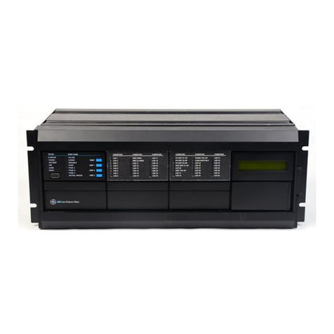
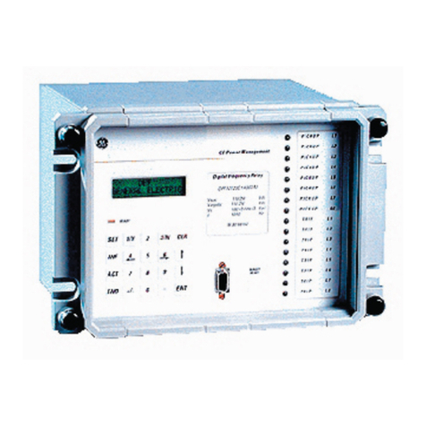
GE P741 User manual

GE Energy Connections
Grid Solutions
MiCOM P40 Agile
P741, P742, P743
Technical Manual
Busbar Differential Protection Relay
Hardware version: J and K
Software version: 51
Publication reference: P74x/EN M/Na7


CONTENTS
Safety Section
Section 1 Introduction P74x/EN IT/Na7
Section 2 Technical Data P74x/EN TD/Na7
Section 3 Getting Started P74x/EN GS/Na7
Section 4 Settings P74x/EN ST/Na7
Section 5 Operation P74x/EN OP/Na7
Section 6 Application Notes P74x/EN AP/Na7
Section 7 Programmable Logic P74x/EN PL/Na7
Section 8 Measurements and Recording P74x/EN MR/Na7
Section 9 Firmware Design P74x/EN FD/Na7
Section 10 Commissioning P74x/EN CM/Na7
Section 11 Maintenance P74x/EN MT/Na7
Section 12 Troubleshooting P74x/EN TS/Na7
Section 13 SCADA Communications P74x/EN SC/Na7
Section 14 Symbols and Glossary P74xEN SG/Na7
Section 15 Installation P74x/EN IN/Na7
Section 16 Firmware and Service Manual Version History P74xEN VH/Na7
TD
IT
ST
GS
OP
AP
PL
MR
FD
CM
VH
TS
SC
SG
IN
MT
Appendix A


Introduction
P74x/EN IT/N
a7
MiCOM P74
1, P742, P743
IT
INTRODUCTION
Hardware Suffix: J and K
Software Version: 51

P74
x/EN IT/Na7
Introduction
MiCOM P741, P742, P743

P74
x/EN IT/Na7
Introduction
(IT) 1
-2
MiCOM P741, P742, P743
IT

Introduction
P74x/EN IT/N
a7
MiCOM P741, P742, P743
(IT) 1-
3
IT
1. DOCUMENTATION STRUCTURE
The manual provides a functional and technical description of the MiCOM protection relay
and a comprehensive set of instructions for the relay’s use and application.
The section contents are summarized below:
P74x/EN IT Introduction
A guide to the MiCOM range of relays and the documentation structure. General safety
aspects of handling Electronic Equipment is discussed with particular reference to relay
safety symbols. Also a general functional overview of the relay and brief application
summary is given.
P74x/EN TD Technical Data
Technical data including setting ranges, accuracy limits, recommended operating conditions,
ratings and performance data. Compliance with norms and international standards is quoted
where appropriate.
P74x /EN GS Getting Started
A guide to the different user interfaces of the protection relay describing how to start using it.
This section provides detailed information regarding the communication interfaces of the
relay, including a detailed description of how to access the settings database stored within
the relay.
P74x /EN ST Settings
List of all relay settings, including ranges, step sizes and defaults, together with a brief
explanation of each setting.
P74x /EN OP Operation
A comprehensive and detailed functional description of all protection and non-protection
functions.
P74x /EN AP Application Notes
This section includes a description of common power system applications of the relay,
calculation of suitable settings, some typical worked examples, and how to apply the settings
to the relay.
P74x /EN PL Programmable Logic
Overview of the programmable scheme logic and a description of each logical node. This
section includes the factory default (PSL) and an explanation of typical applications.
P74x /EN MR Measurements and Recording
Detailed description of the relays recording and measurements functions including the
configuration of the event and disturbance recorder and measurement functions.
P74x /EN FD Firmware Design
Overview of the operation of the relay’s hardware and software. This section includes
information on the self-checking features and diagnostics of the relay.
P74x /EN CM Commissioning
Instructions on how to commission the relay, comprising checks on the calibration and
functionality of the relay.
P74x /EN MT Maintenance
A general maintenance policy for the relay is outlined.
P74x /EN TS Troubleshooting
Advice on how to recognize failure modes and the recommended course of action. Includes
guidance on who in General Electric to contact for advice.

P74
x/EN IT/Na7
Introduction
(IT) 1
-4
MiCOM P741, P742, P743
IT
P74x /EN SC SCADA Communications
This section provides an overview regarding the SCADA communication interfaces of the
relay. Detailed protocol mappings, semantics, profiles and interoperability tables are not
provided within this manual. Separate documents are available per protocol, available for
download from our website.
P74x /EN SG Symbols and Glossary
List of common technical abbreviations found within the product documentation.
P74x /EN IN Installation
Recommendations on unpacking, handling, inspection and storage of the relay. A guide to
the mechanical and electrical installation of the relay is provided, incorporating earthing
recommendations. All external wiring connections to the relay are indicated.
P74x /EN VH Firmware and Service Manual Version History
History of all hardware and software releases for the product.

Introduction
P74x/EN IT/N
a7
MiCOM P741, P742, P743
(IT) 1-
5
IT
2. INTRODUCTION TO MiCOM
MiCOM is a comprehensive solution capable of meeting all electricity supply requirements. It
comprises a range of components, systems and services from General Electric.
Central to the MiCOM concept is flexibility.
MiCOM provides the ability to define an application solution and, through extensive
communication capabilities, integrate it with your power supply control system.
The components within MiCOM are:
−P range protection relays;
−C range control products;
−M range measurement products for accurate metering and monitoring;
−S range versatile PC support and substation control packages.
MiCOM products include extensive facilities for recording information on the state and
behaviour of the power system using disturbance and fault records. They can also provide
measurements of the system at regular intervals to a control centre enabling remote
monitoring and control to take place.
For up-to-date information on any MiCOM product, visit our website:
www.gegridsolutions.com

P74
x/EN IT/Na7
Introduction
(IT) 1
-6
MiCOM P741, P742, P743
IT
3. PRODUCT SCOPE
The P74x differential busbar protection relays have been designed for the protection of a
wide range of substation busbars from distribution to transmission voltage levels. The relays
include a comprehensive range of non-protection features to aid with system diagnosis and
fault analysis. The P74x offers integral biased differential busbar, breaker failure, dead zone,
overcurrent and earth-fault protection and is suitable for application on solidly grounded,
impedance grounded, Petersen coil grounded and isolated systems. The relays are
especially suitable where a complete scheme solution is required.
The scheme comprises of three relays:
•The P741 (Central Unit),
•The P742 and P743 (Peripheral Units).
Which, together with the topology configuration software and the dynamic synoptic
monitoring tool, allow full flexibility for all configurations.
3.1 Functional overview
The P74x Busbar protection contains a wide variety of protection functions. The protection
features are summarized below:
Protection Functions Overview
ANSI IEC 61850 Function P741 P742 P743
87BB / P PhsPDIF Phase segregated biased current differential high speed and
delayed busbar protection
•
- -
87CZ / P CzPPDIF Check Zone segregated biased phase current differential
high speed and delayed busbar protection
•
- -
87BB / N NeuPDIF Sensitive earth fault bias current controlled busbar protection
•
- -
87 CZ/ N CzNPDIF Check Zone segregated biased earth current controlled
busbar protection
•
- -
50 / 51 / P OcpPTOC Phase overcurrent protection (2 stages) -
•
•
50 / 51 / N EfmPTOC Earth overcurrent protection (2 stages) -
•
•
50ST / P DzpPhsPTOC
Dead zone phase protection (short zone between CTs and
open CBs) -
•
•
50ST / N DzpEfmPTOC
Dead zone earth protection (short zone between CTs and
open CBs) -
•
•
CTS Current transformer supervision
•
•
•
50BF RBRF Breaker failure protection (LBB)
•
•
•
ISL Isolator discrepancy alarm -
•
•
Fibre optic signalling channel
•
•
•
OptGGIO Digital inputs (according to product) * 8 8/16 16/24
RlyGGIO Output relays (according to product) * 8 8/12 12/16/20
High Break relays (according to product) * 4 4/8
Virtual Digital inputs (via fibre communication) 16 16 16
Virtual Output relays (via fibre communication) 16 16 16
Front communication port (RS232)
•
•
•
Rear communication port (Kbus/EIA(RS)485)
•
•
•
Second Rear communication port (Kbus/EIA(RS)485)
•
-
•
Rear communication port (Ethernet) * Option - Option
Time synchronisation port (IRIG-B) * Option Via CU Via CU
Redundant Ethernet port Option - Option
FnkGGIO Function keys 10 - 10
LedGGIO Programmable tri-colour LEDs 18 - 18
* Refer to the data sheet for model selection

Introduction
P74x/EN IT/N
a7
MiCOM P741, P742, P743
(IT) 1-
7
IT
The P74x supports the following relay management functions in addition to the functions
illustrated above.
•Trip circuit and coil supervision
•4 Alternative setting groups
•Programmable function keys (P741 and P743)
•Control inputs
•Programmable scheme logic
•Programmable allocation of digital inputs and outputs
•Sequence of event recording
•Comprehensive disturbance recording (waveform capture)
•Fully customizable menu texts
•Multi-level password protection
•Power-up diagnostics and continuous self-monitoring of relay
Application overview
FIGURE 1: FUNCTIONAL DIAGRAM

P74
x/EN IT/Na7
Introduction
(IT) 1
-8
MiCOM P741, P742, P743
IT
3.2 Ordering options
Information Required with Order
Variants
P741 Busbar Protection Relay P741
Vx Aux Rating
24 - 48 Vdc 7
48 - 125 Vdc (40 - 100 Vac) 8
110 - 250 Vdc (100 - 240 Vac) 9
Communication Boards
1 communication board (1 to 4 Peripheral Unit) 1
2 communication board (to 8 Peripheral Unit) 2
3 communication board (to 12 Peripheral Unit) 3
4 communication board (to 16 Peripheral Unit) 4
5 communication board (to 20 Peripheral Unit) 5
6 communication board (to 24 Peripheral Unit) 6
7 communication board ( to 28 Peripheral Unit) 7
Hardware Options
Standard - None 1
IRIG-B Only (modulated) 2
IRIG-B (Demodulated) C
Ethernet (100 Mbits/s) without IRIG-B 6
Ethernet (100Mbit/s) plus IRIG-B (Modulated) A
Ethernet (100Mbit/s) plus IRIG-B (Un-modulated) B
2nd Rear Port & InterMiCOM E
2nd Rear Port & InterMiCOM & IRIG-B (Modulated) F
Redundant Ethernet Self-Healing Ring, 2 multi-mode fibre ports + Modulated IRIG-B G
Redundant Ethernet Self-Healing Ring, 2 multi-mode fibre ports + Un-modulated IRIG-B H
Redundant Ethernet RSTP, 2 multi-mode fibre ports + Modulated IRIG-B J
Redundant Ethernet RSTP, 2 multi-mode fibre ports + Un-modulated IRIG-B K
Redundant Ethernet Dual-Homing Star, 2 multi-mode fibre ports + Modulated IRIG-B L
Redundant Ethernet Dual-Homing Star, 2 multi-mode fibre ports + Un-modulated IRIG-B M
Redundant Ethernet PRP/HSR, 2 fibre ports + Modulated IRIG-B N
Redundant Ethernet PRP/HSR, 2 fibre ports + Unmodulated IRIG-B P
Product Specific
Fixed A
Protocol Options
K-Bus/Courier
IEC60870-5-103 (Via KITZ274)
Courier (K-Bus), IEC60870-5-103 via KITZ274 (Supplied as Courier. KITZ274 to be ordered)
Additional IEC61850
Mounting
Panel Mounting, with harsh environment coating M
Language
Multilingual - English, French, German, Spanish 0
Multilingual - English, French, German, Russian 5
Software Issue
Unless specified the latest version will be delivered **
Customisation
Default 0
Customer specific A
Central Networks Version 5
Design Suffix
Order Number
1
6

Introduction
P74x/EN IT/N
a7
MiCOM P741, P742, P743
(IT) 1-
9
IT
Information Required with Order
Variants
P742 Busbar Protection Peripheral Unit (40TE) P742
Vx Aux Rating
24 - 54Vdc 7
48 - 125Vdc (40 - 100Vac) 8
110 - 250Vdc (100 - 240Vac) 9
Hardware Options
Without CT Input 0
With In = 1/5A CT Input 1
Hardware Options
Standard - None 1
Product Specific
8 Relays Outputs and 16 Status Inputs A
8 Relays Outputs, 4 High Break and 8 Status Inputs B
Protocol Options
K-Bus/Courier
IEC60870-5-103 (Via KITZ274)
Mounting
Flush Panel Mounting, with Harsh Environment Coating M
Language
Multilingual - English, French, German, Spanish 0
Multilingual - English, French, German, Russian 5
Software Issue
Unless specified the latest version will be delivered **
Customisation
Default 0
Customer specific A
Central Networks Version 5
Design Suffix
Order Number
1

P74
x/EN IT/Na7
Introduction
(IT) 1
-10
MiCOM P741, P742, P743
IT
Information Required with Order
Variants
P743 Busbar Protection Peripheral Unit (60TE) P743
Vx Aux Rating
24 - 54Vdc 7
48 - 125Vdc (40 - 100Vac) 8
110 - 250Vdc (100 - 240Vac) 9
Hardware Options
Without CT Input 0
With In = 1/5A CT Input 1
IEC 61850-9-2LE Sampled Analogue Values Ethernet board * C
Hardware Options
Standard - None 1
Ethernet (100 Mbits/s) without IRIG-B 6
2nd Rear Port & InterMiCOM & IRIG-B (Modulated) E
Redundant Ethernet Self-Healing Ring, 2 multi-mode fibre ports + Modulated IRIG-B G
Redundant Ethernet Self-Healing Ring, 2 multi-mode fibre ports + Un-modulated IRIG-B H
Redundant Ethernet RSTP, 2 multi-mode fibre ports + Modulated IRIG-B J
Redundant Ethernet RSTP, 2 multi-mode fibre ports + Un-modulated IRIG-B K
Redundant Ethernet Dual-Homing Star, 2 multi-mode fibre ports + Modulated IRIG-B L
Redundant Ethernet Dual-Homing Star, 2 multi-mode fibre ports + Un-modulated IRIG-B M
Redundant Ethernet PRP/HSR, 2 fibre ports + Modulated IRIG-B N
Redundant Ethernet PRP/HSR, 2 fibre ports + Unmodulated IRIG-B P
Product Specific
16 Relays Outputs and 24 Status Inputs ** A
16 Relays Outputs, 4 High Break and 16 Status Inputs B
8 Relays Outputs, 4 High Break and 24 Status Inputs C
8 Relays Outputs, 8 High Break and 16 Status Inputs D
Protocol Options
K-Bus/Courier
IEC60870-5-103 (Via KITZ274)
Courier (K-Bus), IEC60870-5-103 via KITZ274 (Supplied as Courier. KITZ274 to be ordered)
Additional IEC61850
Mounting
Panel Mounting, with Harsh Environment Coating M
Language
Multilingual - English, French, German, Spanish 0
Multilingual - English, French, German, Russian 5
Software Issue
Unless specified the latest version will be delivered **
Customisation
Default 0
Customer specific A
Central Networks Version 5
Design Suffix
*Only available with '60' software
** 21 Relay Outputs and 24 Status Inputs For Suffix 'B' devices
Order Number
1
6

Technical Data
P74x/EN TD/N
a7
MiCOM P74
1, P742, P743
TD
TECHNICAL DATA
Hardware Suffix: J and K
Software Version: 51

P74
x/EN TD/Na7
Technical Data
MiCOM P74
1, P742, P743

Technical Data
P74x/EN TD/N
a7
MiCOM P74
1, P742, P743 (TD) 2-
3
TD
Technical Data
Mechanical Specification
Design
Modular Px40 platform relay:
P741: Size 16“ case (80TE)
P742: Size 8“ case (40TE)
P743: Size 12“ case (60TE)
Mounting is front of panel flush mounting.
Enclosure Protection
Per IEC 60529: 1992:
IP 52 Protection (front panel) against dust and
dripping water,
IP 50 Protection for the rear and sides of the
case against dust,
IP 10 Product safety protection for the rear due
to live connections on the terminal block
Weight
P741 with 7 comm. boards 7.4 kg
with 1 comm. board 6.2 kg
P742 7.5 kg
P743 9.2 kg
Terminals
AC Current and Voltage Measuring Inputs
P742 and P743 only
Located on heavy duty (black) terminal block:
Threaded M4 terminals, for ring lug
connection.
CT inputs have integral safety shorting, upon
removal of the terminal block.
General Input/Output Terminals
For power supply, opto inputs, output contacts
and COM1 rear communications.
Located on general purpose (grey) blocks:
Threaded M4 terminals, for ring lug
connection.
Case Protective Earth Connection
Two rear stud connections (2 P741, 1 P742/3),
threaded M4.
Must be earthed (grounded) using the
protective (earth) conductor for safety,
minimum wire size 2.5mm2.
Front Port Serial PC Interface
EIA RS232 DTE, 9 pin D-type female
connector.
Courier protocol for interface to S1 software.
PEB* rated Maximum cable length 15 m.
Front Download/Monitor Port
EIA RS232, 25 pin D-type female connector.
For firmware downloads.
PEB* rated circuit.
Rear Communications Port
K-Bus/EIA (RS)485 signal levels, two wire
Connections located on general purpose block,
M4 screw.
For screened twisted pair cable, multidrop,
1000 m max.
Courier protocol
SELV* rated circuit
Optional Second Rear Communication Port
EIA(RS)232, 9 pin D-type female connector,
socket SK4.
Courier protocol: K-Bus, EIA(RS)232, or
EIA(RS)485 connection.
Maximum cable run length: 15m.
Optional Rear EIA(RS)232 InterMiCOM Port
For “MODEM” InterMiCOM teleprotection
schemes.
EIA(RS)232, 9 pin D-type female connector,
socket SK5.
Isolation to SELV* level.
Maximum cable run length to MODEM 15m.
Optional Rear IRIG-B Interface modulated
or un-modulated
P741 only
(P742 & P743 synchronized by the P741)
BNC socket
SELV* rated circuit
50 ohm coaxial cable.
*: PEB = Protective equipotential bonded
*: SELV = Safety/Separated extra low voltage
Both PEB and SELV circuits are safe to touch
after a single fault condition.
Optical Fiber Connection
BFOC 2.5 (ST®) interface for multi-mode glass
fibre type 62.5/125 µm, as per IEC 874-10, 850
nm short-haul fibres, one Tx and one Rx.
Optical budget: 5.6 dB
Data rate:2.5 Mbits
Max Length: 1000 m
Optional Rear Ethernet Connection for IEC
61850
10BaseT / 100BaseTX Communications
Interface in accordance with IEEE802.3 and
IEC61850
Isolation: 1.5kV
Connector type: RJ45
Cable type: Screened Twisted Pair (STP)
Max. cable length: 100m

P74
x/EN TD/Na7
Technical Data
(TD) 2
-4 MiCOM P74
1, P742, P743
TD
100 Base FX Interface
Interface in accordance with IEEE802.3 and
IEC61850
Wavelength: 1300nm
Fiber: multi-mode 50/125µm or 62.5/125µm
Connector style: BFOC 2.5 -(ST®)
Optional Rear redundant Ethernet
connection for IEC 61850
100 Base FX Interface
Interface in accordance with IEEE802.3 and
IEC61850
Wavelength: 1300nm
Fiber: multi-mode 50/125µm or 62.5/125µm
Connector style: BFOC 2.5 -(ST®)
Transmitter optical characteristics 100 base FX
interface
Transmitter Optical Characteristics – 100
base FX interface
(TA = 0°C to 70°C, VCC = 4.75 V to 5.25 V)
Parameter
Sym
Min.
Typ.
Max
Unit
Output Optical Power
BOL: 62.5/125 µm,
NA = 0.275 Fiber
EOL
POUT –19
–20 –16.8 –14 dBm
avg.
Output Optical Power
BOL: 50/125 µm,
NA = 0.20 Fiber EOL
POUT –22.5
–23.5 –20.3 –14 dBm
avg.
Optical Extinction
Ratio
10
–10
%
dB
Output Optical Power
at Logic “0” State
POUT
(“0”)
–45 dBm
avg.
BOL – Beginning of life
EOL – End of life
Receiver Optical Characteristics – 100 base
FX interface
(TA = 0°C to 70°C, VCC = 4.75 V to 5.25 V)
Parameter Sym Min. Typ. Max. Unit
Input Optical Power
Minimum at Window
Edge
P
IN
Min.
(W) –33.5 –31 dBm
avg.
Input Optical Power
Minimum at Eye
Center
P
IN
Min.
(C) –34.5 –31.8 dBm
avg.
Input Optical Power
Maximum
P
IN
Max. –14 –11.8
dBm
avg.
Fiber defect connector (watchdog relay) –
Redundant Ethernet board
Connector (3 terminals): 2NC contacts
Rated voltage: 250 V
Continuous current: 5 A
Short duration current: 30 A for 3 s
Breaking capacity
DC: 50 W resistive
DC: 25 W resistive
AC: 1500 VA resistive (cos φ= unity)
AC: 1500 VA inductive (cos φ= unity)
Subject to maxima of 5 A and 250 V
Ratings
AC Measuring Inputs
Nominal frequency: 50 and 60 Hz (settable)
Operating range: 45 to 65 Hz
Phase rotation: ABC or ACB
AC Current
Nominal current (In): 1 and 5 A dual rated.
(1A and 5A inputs use different transformer tap
connections, check correct terminals are
wired).
Nominal burden per phase
1 A: <0.04VA at rated current
Impedance per phase
1 A: <40mΩover 0 - 30In
Nominal burden per phase
5 A: <0.15VA at rated current
Impedance per phase
5 A: <8mΩover 0 - 30In
Thermal withstand:
continuous 4 In
for 10 s: 30 In
for 1 s; 100 In
Linear to 64 In (non-offset AC current).
Power supply
Auxiliary Voltage (Vx)
Three ordering options:
(i) Vx: 24 to 48 Vdc
(ii) Vx: 48 to 110 Vdc,
and 40 to 100 Vac (rms.)
(iii) Vx: 110 to 250 Vdc,
and 100 to 240 Vac (rms.).
Operating Range
(i) 19 to 65 V (dc only for this variant)
(ii) 37 to 150 V(dc), 32 to 110 V (ac)
(iii) 87 to 300 V(dc), 80 to 265 V (ac).
With a tolerable ac ripple of up to 12 % for a dc
supply, per IEC 60255-11: 1979.
Nominal Burden
Quiescent burden:
P741: 37 to 41 W
P742: 16 to 23 W
P743: 22 to 32 W
Additions for energised binary inputs/outputs:
Per opto input:
0.09 W…(24 to 54 V),
0.12 W…(110/125 V),
0.19 W…(220/250 V).
Per energised output relay: 0.13 W
Per energised high break output relay: * 0.73W
Power-up Time
Time to power up < 30 s.
This manual suits for next models
2
Table of contents
Other GE Relay manuals
Popular Relay manuals by other brands

ABB
ABB SPAU 140 C User manual and technical description

Kyongbo Electric
Kyongbo Electric K-PAM 10 Series user manual

Mitsubishi Electric
Mitsubishi Electric MELPRO-A Series instruction manual

Pilz
Pilz PNOZ Ex operating instructions

ABB
ABB IRP Instruction leaflet

123electric
123electric 123/SmartRelay manual

Siemens
Siemens SIRIUS 3SU140 1E Series Original operating instructions

IDEC
IDEC HR1S-AC operating instructions

Elko
Elko EKO0727X user guide

Pfeiffer Vacuum
Pfeiffer Vacuum HiPace PM 071 282-X operating instructions

Midcontinent
Midcontinent MD41-244 Installation manual and operating instructions

Zamel
Zamel Exta PBM-03 instruction manual